Table of Contents
Advertisement
Quick Links
Advertisement
Table of Contents

Subscribe to Our Youtube Channel
Related Manuals for GIGA-BYTE TECHNOLOGY MDH11BM


Summary of Contents for GIGA-BYTE TECHNOLOGY MDH11BM
- Page 1 MDH11BM Intel Socket LGA1151 processor motherboard ® User's Manual Rev. 1002...
- Page 2 Copyright © 2016 GIGA-BYTE TECHNOLOGY CO., LTD. All rights reserved. The trademarks mentioned in this manual are legally registered to their respective owners. Disclaimer Information in this manual is protected by copyright laws and is the property of GIGABYTE. Changes to the specifications and features in this manual may be made by GIGABYTE without prior notice.
-
Page 3: Table Of Contents
Table of Contents Box Contents ........................4 MDH11BM Motherboard Layout ..................5 Block Diagram .........................7 Chapter 1 Hardware Installation ..................8 Installation Precautions ..................8 1-2 Product Specifications ..................9 Installing the CPU and CPU Cooler ............... 11 1-3-1 Installing the CPU ....................11 1-3-2 Installing the CPU Cooler ..................13... -
Page 4: Box Contents
Box Contents Motherboard Driver CD I/O Shield • The box contents above are for reference only and the actual items shall depend on the product package you obtain. The box contents are subject to change without notice. • The motherboard image is for reference only. - 4 -... -
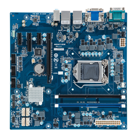
Page 5: Mdh11Bm Motherboard Layout
MDH11BM Motherboard Layout 27 28 29 16 15 - 5 -... - Page 6 Item Code Description AUDIO Audio connectors USB30_LAN2 RJ45 LAN port (top) / USB 3.0 ports (buttom) RJ45 LAN port (top) / USB 3.0 ports USB30_LAN1 (buttom) VGA_DVI VGA port (top)/DVI-D port Serial port (top)/HDMI port (bottom- COM_1/HDMI right corner) SYS_FAN1 System fan connector #1 ATX12V_2X4 8 pin power connector Intel LGA 1151 socket CPU_FAN CPU fan connector DDR4_1...
-
Page 7: Block Diagram
Block Diagram - 7 -... -
Page 8: Chapter 1 Hardware Installation
Chapter 1 Hardware Installation Installation Precautions The motherboard contains numerous delicate electronic circuits and components which can become damaged as a result of electrostatic discharge (ESD). Prior to installation, carefully read the user's manual and follow these procedures: • Prior to installation, do not remove or break motherboard S/N (Serial Number) sticker or warranty sticker provided by your dealer. These stickers are required for warranty validation. • Always remove the AC power by unplugging the power cord from the power outlet before installing or removing the motherboard or other hardware components. • When connecting hardware components to the internal connectors on the motherboard, make sure they are connected tightly and securely. -
Page 9: Product Specifications
1-2 Product Specifications Supports Intel Core i7-6700 processors in Socket LGA1151 Š ® Support Up to 65W Š L2/L3 cache varies with CPU Š Chipset Intel H110 Express chipset Š ® Memory 2 x DDR4 slots support 2133MHz Š Supports Dual channel architecture Š Support up to 32GB Š... - Page 10 Hardware System voltage detection Š Monitor CPU/System temperature detection Š CPU/System fan speed control Š * W hether the CPU/system fan speed control function is supported will depend on the CPU/system cooler you install. BIOS AMI BIOS Š Form Factor uATX Form Factor; 9.6 inch x 9.6 inch Š GIGABYTE reserves the right to make any changes to the product specifications and product-related information without prior notice.
-
Page 11: Installing The Cpu And Cpu Cooler
Installing the CPU and CPU Cooler Read the following guidelines before you begin to install the CPU: • Make sure that the motherboard supports the CPU. • Always turn off the computer and unplug the power cord from the power outlet before installing the CPU to prevent hardware damage. • Locate the pin one of the CPU. The CPU cannot be inserted if oriented incorrectly. (Or you may locate the notches on both sides of the CPU and alignment keys on the CPU socket.) • Apply an even and thin layer of thermal grease on the surface of the CPU. • Do not turn on the computer if the CPU cooler is not installed, otherwise overheating and damage of the CPU may occur. - Page 12 B. Follow the steps below to correctly install the CPU into the motherboard CPU socket. Before installing the CPU, make sure to turn off the computer and unplug the power cord from the power outlet power plug to prevent any damage to prevent damage to the CPU. Step 1: Step 2: Gently press the CPU socket lever handle down...
-
Page 13: Installing The Cpu Cooler
1-3-2 Installing the CPU Cooler Follow the steps below to correctly install the CPU cooler on the motherboard. (The following procedure uses Intel boxed cooler as the example cooler.) ® Male Push Direction of the Arrow Sign on The Top the Male Push of Female Push Pin Female Push Pin Step 1: Step 2: Apply an even and thin layer of thermal paste on Before installing the cooler, note the direction of the arrow sign on the male push pin. (Turning the surface of the installed CPU. the push pin along the direction of the arrow is for removing the cooler, and the opposite direction is for installing it..) Step 3:... -
Page 14: Installing The Memory
Installing the Memory Read the following guidelines before you begin to install the memory: • Make sure that the motherboard supports the memory. It is recommended that memory of the same capacity, brand, speed, and chips be used. • Always turn off the computer and unplug the power cord from the power outlet before installing the memory to prevent hardware damage. • Memory modules have a foolproof design. A memory module can be installed in only one direction. If you are unable to insert the memory, switch the direction. 1-4-1 Installing a Memory Before installing a memory module, make sure to turn off the computer and unplug the power cord from the power outlet to prevent damage to the memory module. -
Page 15: Back Panel Connectors
Back Panel Connectors Serial Port Connects to serial-based mouse or data processing devices. HDMI Port The HDMI (High-Definition Multimedia Interface) provides an all-digital audio/video interface to transmit the uncompressed audio/video signals and is HDCP compliant. Connect the HDMI audio/video device to this port. The HDMI Technology can support a maximum resolution of 1920x1080p but the actual resolutions supported depend on the monitor being used. • When After installing the HDMI device, make sure the default device for sound playback is the HDMI device. (The item name may differ by operating system. Refer the figures below for details.), and enter BIOS Setup, then set Onboard VGA output connect to D-SUB/ HDMI under Advanced BIOS Features.. • Please note the HDMI audio output only supports AC3, DTS and 2-channel-LPCM formats. (AC3 and DTS require the use of an external decoder for decoding.) Video Port The video in port allows connect to video in, which can also apply to video loop thru function. - Page 16 Connection/ Speed LED Activity LED Connection/Speed LED: Activity LED: State Description State Description Orange 1 Gbps data rate Blinking Data transmission or receiving is occurring Green 100 Mbps data rate No data transmission or receiving is occurring LAN Port 10 Mbps data rate • When removing the cable connected to a back panel connector, first remove the cable from your device and then remove it from the motherboard.
-
Page 17: Internal Connectors
Internal Connectors COM4 ATX12V_2X4 COM3 SATAIII_0/1/2/3 COM2 CPU_FAN F_AUDIO SYS_FAN1 F_PANEL SYS_FAN2 FUSB2_1 CLR_CMOS FUSB2_2 Read the following guidelines before connecting external devices: • First make sure your devices are compliant with the connectors you wish to connect. • Before installing the devices, be sure to turn off the devices and your computer. Unplug the power cord from the power outlet to prevent damage to the devices. • After installing the device and before turning on the computer, make sure the device cable has been securely attached to the connector on the motherboard. - 17 - Hardware Installation... - Page 18 1/2) ATX/ATX12V_2X4 (2x4 12V Power Connector and 2x12 Main Power Connector) With the use of the power connector, the power supply can supply enough stable power to all the components on the motherboard. Before connecting the power connector, first make sure the power supply is turned off and all devices are properly installed. The power connector possesses a foolproof design.
- Page 19 3) SATA1/SATA2 (SATA 6Gb/s Connectors) The SATA connectors conform to SATA 6Gb/s standard and are compatible with SATA 3Gb/s standard. Each SATA connector supports a single SATA device. SATAIII_0 SATAIII_1 SATAIII_2 SATAIII_3 Pin No. Definition SATAIII_0 SATAIII_1 SATAIII_2 SATAIII_3 4/5/6) CPU_FAN/SYS_FAN0/SYS_FAN1 (CPU Fan/System Fan Headers) The motherboard has one 4-pin CPU fan header (CPU_FAN), and two 4-pin (SYS_FAN) system fan headers. Most fan headers possess a foolproof insertion design. When connecting a fan cable, be sure to connect it in the correct orientation (the black connector wire is the ground wire). The motherboard supports CPU fan speed control, which requires the use of a CPU fan with fan speed control design. For optimum heat dissipation, it is recommended that a system fan be installed inside the chassis.
- Page 20 COMB 7/8) F_USB1/F_USB2 (USB 2.0 Headers) The headers conform to USB 2.0 specification. Each USB header can provide two USB ports via an optional USB bracket. For purchasing the optional USB bracket, please contact the local dealer. PWR_LED Pin No. Definition F_USB 1 Power (5V) 2 Power (5V) USB DX- CLR_CMOS USB DY- BIOS_WP COMB USB DX+ USB DY+ CLR_CMOS BIOS_WP...
- Page 21 9/10/11) COM2/COM3/COM4 (Serial Port Cable Connectors #2/#3/#4) The COM header can provide one serial port via an optional COM port cable. For purchasing the optional COM port cable, please contact the local dealer. Pin No. Definition NDCD- NSIN NSOUT- COM2 NDTR- COM3 NDSR- COM4 NRTS- NCTS- NRI- 12) F_AUDIO (Front Panel Audio Header) The front panel audio header supports Intel High Definition audio (HD) and AC'97 audio. You may connect your chassis front panel audio module to this header. Make sure the wire assignments of the module connector match the pin assignments of the motherboard header. Incorrect connection between the...
- Page 22 13) F_PANEL (Front Panel Header) Connect the power switch, reset switch, speaker, chassis intrusion switch/sensor and system status indicator on the chassis to this header according to the pin assignments below. Note the positive and negative pins before connecting the cables. Pin No. Signal Name Definition 1 HD+ Hard Disk LED Signal anode (+) 2...
- Page 23 14) BAT (Battery Scoket) The battery provides power to keep the values (such as BIOS configurations, date, and time information) in the CMOS when the computer is turned off. Replace the battery when the battery voltage drops to a low level, or the CMOS values may not be accurate or may be lost. • Always turn off your computer and unplug the power cord before replacing the battery. • Replace the battery with an equivalent one. Danger of explosion if the battery is replaced with an incorrect model. • Contact the place of purchase or local dealer if you are not able to replace the battery by yourself or uncertain about the battery model. • Used batteries must be handled in accordance with local environmental regulations. 15) CLR_CMOS (Clearing CMOS Jumper) Use this jumper to clear the CMOS values (e.g. date information and BIOS configurations) and reset the CMOS values to factory defaults. To clear the CMOS values, place a jumper cap on the two pins to temporarily short the two pins or use a metal object like a screwdriver to touch the two pins for a few seconds.
-
Page 24: Chapter 2 Bios Setup
Chapter 2 BIOS Setup BIOS (Basic Input and Output System) records hardware parameters of the system in the CMOS on the motherboard. Its major functions include conducting the Power-On Self-Test (POST) during system startup, saving system parameters and loading operating system, etc. BIOS includes a BIOS Setup program that allows the user to modify basic system configuration settings or to activate certain system features. When the power is turned off, the battery on the motherboard supplies the necessary power to the CMOS to keep the configuration values in the CMOS. To access the BIOS Setup program, press the <DEL> key during the POST when the power is turned on. - Page 25 Main This setup page includes all the items in standard compatible BIOS Advanced This setup page includes all the items of AMI BIOS special enhanced features. (ex: Auto detect fan and temperature status, automatically configure hard disk parameters.) Chipset Northbridge and Southbridge additional features configuration. Boot This setup page provides items for configuration of boot sequence. Security Change, set, or disable supervisor and user password. Configuration supervisor password allows you to restrict access to the system and BIOS Setup. A supervisor password allows you to make changes in BIOS Setup. A user password only allows you to view the BIOS settings but not to make changes.
-
Page 26: The Main Menu
The Main Menu Once you enter the BIOS Setup program, the Main Menu (as shown below) appears on the screen. Use arrow keys to move among the items and press <Enter> to accept or enter other sub-menu. Main Menu Help The on-screen description of a highlighted setup option is displayed on the bottom line of the Main Menu. Submenu Help While in a submenu, press <F1> to display a help screen (General Help) of function keys available for the menu. Press <Esc> to exit the help screen. Help for each item is in the Item Help block on the right side of the submenu. • When the system is not stable as usual, select the Restore Defaults item to set your system to its defaults. • The BIOS Setup menus described in this chapter are for reference only and may differ by BIOS version. BIOS Setup - 26 -... - Page 27 BIOS Information Project Name Display name of the project. BIOS Version Display version number of the BIOS. BIOS Build Date and Time Displays the date and time when the BIOS setup utility was created. LAN MAC Address Displays the LAN MAC address information. Memory Information Total Memory Display the total memory size of the installed memory. ME FW Version Display the ME firmware version. System Date Set the date following the weekday-month-day- year format.
-
Page 28: Advanced Menu
Advanced Menu The Advanced menu display submenu options for configuring the function of various hardware components. Select a submenu item, then press Enter to access the related submenu screen. BIOS Setup - 28 -... -
Page 29: Trusted Computing
2-2-1 Trusted Computing Configuration Security Device Support Select Enabled to activate TPM support feature. Options available: Enabled/Disabled. Default setting is Disabled. Current Status Information Display current TPM status information. - 29 - BIOS Setup... -
Page 30: Super Io Configuration
2-2-2 Super IO Configuration Super IO Configuration Serial Port 1 Configuration Press [Enter] for configuration of advanced items. Serial Port 2 Configuration Press [Enter] for configuration of advanced items. Serial Port 3 Configuration Press [Enter] for configuration of advanced items. Serial Port 4 Configuration Press [Enter] for configuration of advanced items. BIOS Setup - 30 -... - Page 31 2-2-2-1 Serial Port Configuration (for port #1/#2/#3#4) - 31 - BIOS Setup...
- Page 32 BIOS Setup - 32 -...
-
Page 33: Serial Port Configuration (For Port #1/#2/#3#4)
Serial Port Configuration Serial Port When enabled allows you to configure the serial port settings. When set to Disabled, displays no configuration for the serial port. Options available: Enabled/Disabled. Default setting is Enabled. Device Settings Display the specified Serial Port base I/O addressand IRQ. - 33 - BIOS Setup... -
Page 34: Hardware Monitor
2-2-3 Hardware Monitor Press Enter to view the Hardware Monitor screen which displays a real-time record of the CPU/system tem- perature, and fan speed, Items on this window are non-configurable. CPU/System FAN Fail Warning Enable/Disable CPU/System FAN Fail warning alert funciton. Option available: Enabled/Disabled. Default setting for CPU FAN Fail Warning is Enabled. Default setting for System FAN Fail Warning is Disabled. CPU/System FAN Speed Control Enable CPU/System Fan Speed Control function. Option available: Normal/Full Speed. Default setting is Normal. System/CPU Temperature Displays current CPU temperature. CPU/System Fan Speed (RPM) Displays current CPU and system fan speed. VCORE/DDR1.2V/+12V/VCC/VCC3/VSB3V Displays a real-time record of the related system voltage. BIOS Setup - 34 -... -
Page 35: S5 Rtc Wake Settings
2-2-4 S5 RTC Wake Settings Wake system from S5 Enable or disable System wake on alarm event. When enabled, System will wake on the hr:min:sec specified. Default setting is Disabled. Wake up hour (Note) Press <+> and <-> to define the wake up hour. Wake up minute (Note) Press <+> and <-> to define the wake up minute. Wake up second (Note) Press <+> and <-> to define the wake up second. (Note) This item appears when Wake system from S5 is set to Fixed time. - 35 - BIOS Setup... - Page 36 2-2-5 CPU Configuration BIOS Setup - 36 -...
-
Page 37: Cpu Configuration
CPU Configuration CPU Type/Signature/Microcode Patch/CPU Speed/Processor Cores/ Hyper Threading Technology/Intel VT-x Technology/Intel SMX Technology/64bit/ EIST Technology/ CPU C3/C6/C7 State Displays the technical specifications for the installed processor. Cache Information L1 Data Cache/L1 Code Cache /L2 Cache /L3 Cache/L4 Cache Displays the technical specifications for the installed processor. Hyper-threading The Intel Hyper Threading Technology allows a single processor to execute two or more separate threads concurrently. When hyper-threading is enabled, multi-threaded software applications can execute their threads, thereby improving performance. - Page 38 CFG lock Enable/Disable CFG lock. Options available: Enabled/Disabled. Default setting is Disabled. BIOS Setup - 38 -...
-
Page 39: Sata Configuration
2-2-6 SATA Configuration SATA Port 0/1/2/3 Displays the installed HDD devices information. System will automatically detect HDD type. - 39 - BIOS Setup... -
Page 40: Os Selection
2-2-7 OS Selection OS Selection Option Available: Windows8.x/10/Windows 7. Note: You have to select the OS mode in the BIOS setup before installing any OS on your system. LAN PXE OpROM Enable/Disable LAN PXE OpROM. Options available: Enabled/DIsabled. Default setting is Disabled. LAN EFI driver Enable/Disable LAN EFI driver. Options available: Enabled/DIsabled. Default setting is Disabled. Storage Determines which devices system will boot to. Options available: Do not launch/UEFI/Legacy . Default setting is UEFI. BIOS Setup - 40 -... -
Page 41: Chipset Menu
Chipset Menu VT-d Enable/Disable VT-d function. Options available: Enabled/Disabled. Default setting is Enabled. DVMT Pre-Allocated Select DVMT 5.0 Pre-Allocated (Fixed) Graphics Memory size used by the Internal Graphics Device. Options available: 64M/128M/192M/256M/320M/384M/512M. Default setting is 32M. Onboard Audio Enable/Disable onboard audio controller. Options available: Enabled/Disabled. Default setting is Enabled. Onboard LAN Enable/Disable onboard LAN controller. Options available: Enabled/Disabled. Default setting is Enabled. ERP Lowest Power State Mode Enable/Disable ERP Lowest Power State Mode. Options available: Enabled/Disabled. Default setting is Disabled. Restore AC Power Loss This option provides user to set the mode of operation if an AC / power loss occurs. Power On: System power state when AC cord is re-plugged. Power Off: Do not power on system when AC power is back. Last State: Set system to the last sate when AC power is removed. Options available: Power On/Power Off/Last State. Default setting is Power Off. - 41 - BIOS Setup... -
Page 42: Security Menu
Security Menu The Security menu allows you to safeguard and protect the system from unauthorized use by setting up ac- cess passwords. There are two types of passwords that you can set: • Adminstrator Password Entering this password will allow the user to access and change all settings in the Setup Utility. • User Password Entering this password will restrict a user’s access to the Setup menus. To enable or disable this field, a Administrator Password must first be set. A user can only access and modify the System Time, System Date, and Set User Password fields. -
Page 43: Secure Boot Menu
2-4-1 Secure Boot menu System Mode Display the System Mode state. Secure Boot Display the System Mode State. Vendor Keys Display the Vendor Keys information. Secure Boot Secure Boot requires all the applications that are running during the booting process to be pre-signed with valid digital certificates. This way, the system knows all the files being loaded before Windows 8 loads and gets to the login screen have not been tampered with. -
Page 44: Key Management
2-4-1-1 Key Management Key Management This item appears only when the Secure Boot Mode is set to Custom. Provision Factory Default Keys Force the system to Setup Mode. This will clear all Secure Boot Variables such as Platform Key (PK), Key-exchange Key (KEK), Authorized Signature Database (db), and Forbidden Signaures Database (dbx). Options available: Enabled/Disabled. Default setting is Disabled. Enroll All Factory Default Keys Press [Enter] to install all factory default keys. Save All Secure Boot Variables Press [Enter] to save all Secure Boot Variables. Platform Key (PK) Press Enter to configure the advanced items. -
Page 45: Boot Menu
Boot Menu The Boot menu allows you to set the drive priority during system boot-up. BIOS setup will display an error message if the drive(s) specified is not bootable. Boot Configuration Boot Option Priorities Boot Option #1/#2#3 Press Enter to configure the boot priority. By default, the server searches for boot devices in the following secquence: UEFI device. Hard drive. Network device. Hard Drive BBS Priorities Press Enter to configure the boot priority. -
Page 46: Save & Exit Menu
Save & Exit Menu The Exit menu displays the various options to quit from the BIOS setup. Highlight any of the exit options then press Enter. Save Changes and Exit Saves changes made and close the BIOS setup. Options available: Yes/No. Discard Changes and Exit Discards changes made and close the BIOS setup. Options available: Yes/No. Save Changes and Reset Saves changes made and reset the system. Options available: Yes/No. - Page 47 Restore Defaults Loads the default settings for all BIOS setup parameters. Setup Defaults are quite demanding in terms of resources consumption. If you are using low-speed memory chips or other kinds of low-performance components and you choose to load these settings, the system might not function properly. Options available: Yes/No. Save as User Defaults Save to current BIOS settings as user-defined default settings. Restore as User Defaults Load the user-define default settings for all BIOS options Boot Override Allows you to select a device to boot immediately. Press <Enter> on the device you select and select Yes to confirm. Your system will restart automatically and boot from that device. UEFI: Built-in in EFI Shell Press <Enter> on this item to Launch EFI Shell from filesystem device. ME FW Image Re-Flash Enable/Disable reflashing ME firmware. Options available: Enabled/DIsabled. Default setting is Disabled. - 47 - BIOS Setup...
-
Page 48: Flash Your Bios
Flash Your BIOS Follow the steps below to flash your BIOS. Put the BIOS files onto a bootable USB stick. Press F2 and enter into BIOS setup menu. Go to Boot and configure the first boot device to USB disk. BIOS Setup - 48 -... - Page 49 Press F4 and select Yes to save the configuration. Enter the DOS, and type cd <BIOS file >. - 49 - BIOS Setup...
- Page 50 Enter “FLASH.bat” to run the batch file. Wating for the BIOS update. BIOS Setup - 50 -...
- Page 51 When the flashing is completed, the screen will show the following message: FPT Operation Successful Press "Ctrl+alt+del" to exit. Reboot he system and press F2. 10. Enter into the BIOS setup main menu and check the BIOS version. - 51 - BIOS Setup...
Need help?
Do you have a question about the MDH11BM and is the answer not in the manual?
Questions and answers