Table of Contents
Advertisement
Quick Links
Advertisement
Table of Contents

Related Manuals for GIGA-BYTE TECHNOLOGY MZJ19AI


Summary of Contents for GIGA-BYTE TECHNOLOGY MZJ19AI
- Page 1 MZJ19AI Intel J1900 Processor Motherboards ® User's Manual Rev. 1001...
- Page 2 Copyright © 2014 GIGA-BYTE TECHNOLOGY CO., LTD. All rights reserved. The trademarks mentioned in this manual are legally registered to their respective owners. Disclaimer Information in this manual is protected by copyright laws and is the property of GIGABYTE. Changes to the specifications and features in this manual may be made by GIGABYTE without prior notice.
-
Page 3: Table Of Contents
Table of Contents MZJ19AI Motherboard Layout ..................4 Chapter 1 Hardware Installation ..................6 Installation Precautions ..................6 1-2 Product Specifications ..................7 Installing the Memory ..................9 1-3-1 Installing a Memory ....................9 Back Panel Connectors .................. 10 Internal Connectors ..................12 Chapter 2 BIOS Setup ....................21 The Main Menu .................... -
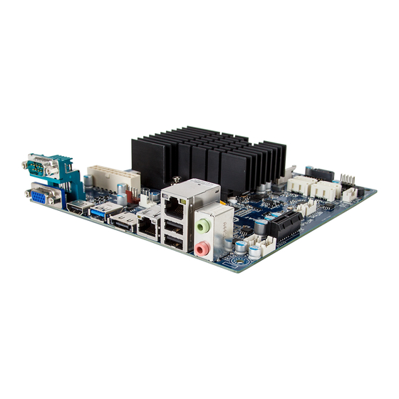
Page 4: Mzj19Ai Motherboard Layout
MZJ19AI Motherboard Layout 5 6 7 - 4 -... - Page 5 Item Code Description AUDIO Audio connectors USB_LAN LAN port (top)/USB 2.0 ports (buttom) LAN port ESATA_CON eSATA connector RUSB30 USB 3.0 port CPU_FAN CPU fan connector HDMI HDMI port VGA_COM1 Serail port (top)/VGA port (buttom) SYS_FAN System fan connector 20 pin power connector SODIMM1 DDR3 SO-DIMM slot Intel SoC J1900 processor...
-
Page 6: Chapter 1 Hardware Installation
Chapter 1 Hardware Installation Installation Precautions The motherboard contains numerous delicate electronic circuits and components which can become damaged as a result of electrostatic discharge (ESD). Prior to installation, carefully read the user's manual and follow these procedures: • Prior to installation, do not remove or break motherboard S/N (Serial Number) sticker or warranty sticker provided by your dealer. -
Page 7: Product Specifications
1-2 Product Specifications Support for Intel Celeron J1900 (2.0 GHz) processor Š ® ® TDP 10W Š Fan-less design Š L1/L2 cache varies with CPU Š Memory 2 x SO-DIMM slots support 1.35V DDR3L 1333MHz Š Support up 8GB Š Audio Realtek ALC269 codec Š... - Page 8 Hardware System voltage detection Š Monitor CPU/System temperature detection Š CPU/System fan speed control Š * Whether the CPU/system fan speed control function is supported will depend on the CPU/system cooler you install. BIOS AMI BIOS Š Form Factor Mini ITX Form Factor; 170CM x 170CM Š...
-
Page 9: Installing The Memory
Installing the Memory Read the following guidelines before you begin to install the memory: • Make sure that the motherboard supports the memory. It is recommended that memory of the same capacity, brand, speed, and chips be used. • Always turn off the computer and unplug the power cord from the power outlet before installing the memory to prevent hardware damage. -
Page 10: Back Panel Connectors
Back Panel Connectors Serial Port Connects to serial-based mouse or data processing devices. Video Port The video in port allows connect to video in, which can also apply to video loop thru function. HDMI Port The HDMI (High-Definition Multimedia Interface) provides an all-digital audio/video interface to transmit the uncompressed audio/video signals and is HDCP compliant. Connect the HDMI audio/video device to this port. - Page 11 LAN2 LAN1 LAN LED Description for LAN1 Connection/ Activity LED Speed LED Connection/Speed LED: Activity LED: State Description State Description Orange 1 Gbps data rate Blinking Data transmission or receiving is occurring Green 100 Mbps data rate No data transmission or receiving is occurring LAN1 Port 10 Mbps data rate LAN LED Description for LAN2...
-
Page 12: Internal Connectors
Internal Connectors TPM_LPC CPU_FAN SATA_LED SYS_FAN GPIO_CNT F_USB SPK_OUT PWR_SATA F_AUDIO SATA1/2/3/4 BAT_CON F_PANEL CLR_CMOS Read the following guidelines before connecting external devices: • First make sure your devices are compliant with the connectors you wish to connect. • Before installing the devices, be sure to turn off the devices and your computer. Unplug the power cord from the power outlet to prevent damage to the devices. - Page 13 1) ATX (2x4 12V Power Connector and 2x12 Main Power Connector) With the use of the power connector, the power supply can supply enough stable power to all the components on the motherboard. Before connecting the power connector, first make sure the power supply is turned off and all devices are properly installed.
- Page 14 2/3) CPU_FAN/SYS_FAN (CPU Fan/System Fan Header) The motherboard has one 4-pin CPU fan header, and one 4-pin system fan header. Most fan headers possess a foolproof insertion design. When connecting a fan cable, be sure to connect it in the correct orientation (the black connector wire is the ground wire).
- Page 15 5) PWR_SATA (SATA 3Gb/s Connector/Support SATA DOM Function) The SATA connectors conform to SATA 3Gb/s standard and are compatible with 1.5Gb/s standard. Each SATA connector supports a single SATA device. Pin No. Definition DEBUG PORT DEBUG PORT 6) SATA1/SATA2/SATA3/SATA4 (SATA 6Gb/s Connectors) The SATA connectors conform to SATA 6Gb/s standard and are compatible with SATA 3Gb/s and 1.5Gb/s standard.
- Page 16 7) F_PANEL (Front Panel Header) Connect the power switch, reset switch, speaker, and system status indicator on the chassis to this header according to the pin assignments below. Note the positive and negative pins before connecting the cables. Pin No. Signal Name Definition Hard Disk LED Signal anode (+) MPD+...
- Page 17 8) TPM_LPC (TPM Module Connector) Pin No. Definition -SIO_PCIRST 3VDUAL DB_LPC25 VCC3 LAD0 SERIRQ_N LAD1 LAD2 No Pin LAD3 -LFRAME 9) SATA_LED (SATA LED GPIO connector) Pin No. Definition HDD_ACT VCC3 -SATA1_LED VCC3 SATA2_LED VCC3 SATA3_LED VCC3 SATA4_LED VCC3 - 17 - Hardware Installation...
- Page 18 10) GPIO_CNT (GPIO connector) Pin No. Definition SOGP0_1 SOGPI_1 SOGP0_2 SOGPI_2 SOGP0_3 SOGPI_3 SOGP0_4 SOGPI_4 SMCLK_N SMDATA_N 11) SPK_OUT (Audio Amplifier Connector) Pin No. Definition OUT_R+ OUT_R- OUT_L- OUT_L+ Hardware Installation - 18 -...
- Page 19 12) F_AUDIO (Front Panel Audio Header) The front panel audio header supports Intel High Definition audio (HD) and AC'97 audio. You may connect your chassis front panel audio module to this header. Make sure the wire assignments of the module connector match the pin assignments of the motherboard header. Incorrect connection between the module connector and the motherboard header will make the device unable to work or even damage it. Pin No. Definition MIC_L MIC_R...
- Page 20 14) CLR_CMOS (Clearing CMOS Jumper) Use this jumper to clear the CMOS values (e.g. date information and BIOS configurations) and reset the CMOS values to factory defaults. To clear the CMOS values, place a jumper cap on the two pins to temporarily short the two pins or use a metal object like a screwdriver to touch the two pins for a few seconds.
-
Page 21: Chapter 2 Bios Setup
Chapter 2 BIOS Setup BIOS (Basic Input and Output System) records hardware parameters of the system in the CMOS on the motherboard. Its major functions include conducting the Power-On Self-Test (POST) during system startup, saving system parameters and loading operating system, etc. BIOS includes a BIOS Setup program that allows the user to modify basic system configuration settings or to activate certain system features. When the power is turned off, the battery on the motherboard supplies the necessary power to the CMOS to keep the configuration values in the CMOS. - Page 22 Main This setup page includes all the items in standard compatible BIOS Advanced This setup page includes all the items of AMI BIOS special enhanced features. (ex: Auto detect fan and temperature status, automatically configure hard disk parameters.) Chipset Northbridge and Southbridge additional features configuration. Boot This setup page provides items for configuration of boot sequence. Security Change, set, or disable supervisor and user password. Configuration supervisor password allows you to restrict access to the system and BIOS Setup. A supervisor password allows you to make changes in BIOS Setup.
-
Page 23: The Main Menu
The Main Menu Once you enter the BIOS Setup program, the Main Menu (as shown below) appears on the screen. Use arrow keys to move among the items and press <Enter> to accept or enter other sub-menu. Main Menu Help The on-screen description of a highlighted setup option is displayed on the bottom line of the Main Menu. - Page 24 BIOS Information Project Name Display name of the project. BIOS Version Display version number of the BIOS. BIOS Build Date and Time Displays the date and time when the BIOS setup utility was created. LAN1/LAN2 MAC Address Displays the LAN1 and LAN2 MAC address information. Memory Information Total Memory Display the total memory size of the installed memory.
-
Page 25: Advanced Menu
Advanced Menu The Advanced menu display submenu options for configuring the function of various hardware components. Select a submenu item, then press Enter to access the related submenu screen. - 25 - BIOS Setup... -
Page 26: Super Io Configuration
2-2-1 Super IO Configuration Super IO Configuration Serial Port 1 Configuration Press [Enter] for configuration of advanced items. BIOS Setup - 26 -... -
Page 27: Serial Port Configuration
2-2-1-1 Serial Port Configuration Serial Port Configuration Serial Port When enabled allows you to configure the serial port settings. When set to Disabled, displays no configuration for the serial port. Options available: Enabled/Disabled. Default setting is Enabled. Device Settings Display the specified Serial Port base I/O addressand IRQ. Change Settings Change Serial Port 0/1 device settings. When set to Auto allows the server’s BIOS or OS to select a configuration. Options available: Auto/IO=3F8; IRQ=4/IO=3F8h; IRQ=3,4,5,6,7,10,11,12/ IO=2F8h;... -
Page 28: Hardware Monitor
2-2-2 Hardware Monitor Press Enter to view the Hardware Monitor screen which displays a real-time record of the CPU/system tem- perature, and fan speed, Items on this window are non-configurable. PC Health Status CPU/System FAN Fail Detect Enable/Disable CPU/System FAN Fail Detect function. Option available: Enabled/Disabled. Default setting is Disabled. CPU/System FAN Speed Control Enable CPU/System Fan Speed Control function. -
Page 29: S5 Rtc Wake Settings
2-2-3 S5 RTC Wake Settings Wake system from S5 Enable or disable System wake on alarm event. When enabled, System will wake on the hr:min:sec specified. Default setting is Disabled. Wake up hour (Note) Press <+> and <-> to define the wake up hour. Wake up minute (Note) Press <+> and <-> to define the wake up minute. Wake up second (Note) Press <+> and <-> to define the wake up second. -
Page 30: Cpu Configuration
2-2-4 CPU Configuration CPU Information Press [Enter] to view the installed CPUinformation. Intel Virtualization Technology Select whether to enable the Intel Virtualization Technology function. VT allows a single platform to run multiple operating systems in independent partitions. Options available: Enabled/Disabled. Default setting is Enabled. Turbo Mode When this feature is enabled, the processor can dynamically overclock one or two of its four processing cores to improve performance with applications that are not multi-threaded or optimized for quad-core... -
Page 31: Cpu Information
2-2-4-1 CPU Information CPU Type/Signature/Microcode Path/Processor Cores/64-bit/Intel HT Technology/ Intel VT-x Technology Displays the technical specifications for the installed processor. Cache Information L1 Data Cache / L1 Code Cache / L2 Cache / L3 Cache Displays the technical specifications for the installed processor. - 31 - BIOS Setup... -
Page 32: Sata Configuration
2-2-5 SATA Configuration SATA Mode Select the on chip SATA type. IDE Mode: When set to IDE, the SATA controller disables its AHCI functions and runs in the IDE emulation mode. AHCI Mode: When set to AHCI,the SATA controller enables its AHCI functionality. Options available: IDE/AHCI/Disabled. -
Page 33: Csm Configuration
2-2-6 CSM Configuration Compatibility Support Module Configuration Press Enter to configure the advanced items. CSM Support Enable/Disable Compatibility Support Module (CSM) support function. Options available: Enabled/Disabled. Default setting is Disabled. • The following five items appears and configurable when the Launch CSM is set to Enabled. • If the Launch CSM is set to Disabled, the following five items will not be able to support Legacy mode. LAN EFI driver (Note) Enable/Disable LAN EFI driver. -
Page 34: Trusted Computing (Optional)
2-2-7 Trusted Computing (Optional) Configuration Security Device Support Select Enabled to activate TPM support feature. Options available: Enabled/Disabled. Default setting is Disabled. Current Status Information Display current TPM status information. BIOS Setup - 34 -... -
Page 35: Intel (R) I210 Gigabit Network Connection
2-2-8 Intel (R) I210 Gigabit Network Connection - 35 - BIOS Setup... - Page 36 NIC Configuration Press [Enter] for configuration of advanced items. Blink LEDs (range 0-15 seconds) Blink LEDs for the specified duration (up to 15 seconds). Press the numberic keys to input the desired value. UEFI Driver Display the UEFI driver information. Adapter PBA Display the Adapter PBA information. Chip Type Display the Chip type. PCI Device ID Display the PCI device ID.
-
Page 37: Driver Health
2-2-9 Driver Health Press Enter to view the submenu screen which displays a real-time record of the LAN controllers, Items on this window are non-configurable. - 37 - BIOS Setup... -
Page 38: Chipset Menu
Chipset Menu DVMT Pre-Allocated Select DVMT 5.0 Pre-Allocated (Fixed) Graphics Memory size used by the Internal Graphics Device. Options available: 64M/128M/192M/256M/320M/384M/512M. Default setting is 64M. Onboard Audio Enable/Disable onboard audio controller. Options available: Enabled/Disabled. Default setting is Enabled. DMIC Support Enable/Disable DMIC Support Options available: Enabled/Disabled. - Page 39 Restore AC Power Loss This option provides user to set the mode of operation if an AC / power loss occurs. Power On: System power state when AC cord is re-plugged. Power Off: Do not power on system when AC power is back. Last State: Set system to the last sate when AC power is removed.
-
Page 40: Security Menu
Security Menu The Security menu allows you to safeguard and protect the system from unauthorized use by setting up ac- cess passwords. There are two types of passwords that you can set: • Adminstrator Password Entering this password will allow the user to access and change all settings in the Setup Utility. •... -
Page 41: Secure Boot Menu
2-4-1 Secure Boot menu System Mode Display the System Mode state. Secure Boot Display the System Mode State. Secure Boot Secure Boot requires all the applications that are running during the booting process to be pre-signed with valid digital certificates. This way, the system knows all the files being loaded before Windows 8 loads and gets to the login screen have not been tampered with. -
Page 42: Key Management
2-4-1-1 Key Management Key Management This item appears only when the Secure Boot Mode is set to Custom. Default Key Provisioning Force the system to Setup Mode. This will clear all Secure Boot Variables such as Platform Key (PK), Key-exchange Key (KEK), Authorized Signature Database (db), and Forbidden Signaures Database (dbx). Options available: Enabled/Disabled. - Page 43 Set new KEK Press [Enter] to configure a new KEK. Append Var to KEK Press [Enter] to load additional KEK from a storage devices for an additional db and dbx management. Authorized Signature Database (DB) Display the status of Authorized Signature Database. Delete DB Press [Enter] to delete the db from your system. Set new DB Press [Enter] to configure a new db.
-
Page 44: Boot Menu
Boot Menu The Boot menu allows you to set the drive priority during system boot-up. BIOS setup will display an error message if the drive(s) specified is not bootable. Boot Configuration Quiet Boot Enables or disables showing the logo during POST. Options available: Enabled/Disabled. Default setting is Disabled. Fast Boot This BIOS feature alows you to decrease the time it takes to boot up the system by skipping certain booting procedures. -
Page 45: Save & Exit Menu
Save & Exit Menu The Exit menu displays the various options to quit from the BIOS setup. Highlight any of the exit options then press Enter. Save Changes and Reset Saves changes made and close the BIOS setup. Options available: Yes/No. Discard Changes and Reset Discards changes made and close the BIOS setup.
Need help?
Do you have a question about the MZJ19AI and is the answer not in the manual?
Questions and answers