Table of Contents
Advertisement
Quick Links
Advertisement
Table of Contents

Related Manuals for Melec GDB-5311A-00


Summary of Contents for Melec GDB-5311A-00
- Page 1 5-phase Stepping Motor Driver GDB-5311A-00 Instructions Manual (For designers' use) Please ensure to read and understand this Instructions Manual before using the product. Please keep this Instructions Manual at hand so that it is always available for reference. PR0818-2...
- Page 2 Instructions Manual Introduction This Instructions Manual describes the safe and proper method of handing "5-phase Stepping Motor Driver GDB-5311A-00" with emphasis on the specifications, assuming that our readers are engaged in designing of control devices incorporating stepping motors. Please ensure to read and understand this Instructions Manual before using the product.
- Page 3 Instructions Manual Descriptions in this manual on safety matters: This product must be operated and used properly. Otherwise, or when it is operated and used erroneously, unforeseen accidents may occur, causing physical injuries or property damages. Majority of these accidents can be avoided if you are well informed of hazardous circumstances in advance.
-
Page 4: Table Of Contents
Instructions Manual Introduction Descriptions in this manual on safety matters: CONTENTS PAGE 1. Safety 1-1. Safety Precautions 1-2. Safety Information for Handling 2. Overview 2-1. Characteristics 2-2. Product Configuration 2-3. Appearance 3. Name and Function of Each Section 3-1. Signal I/O Connector(J1) 3-2. - Page 5 Instructions Manual PAGE 8. Maintenance and Check-up 8-1. Maintenance and Check-up 8-2. Troubleshooting 9. Storing and Disposal 9-1. Storing 9-2. Disposal 10. Specifications 10-1. General Specifications 10-2. I/O Signal Example Circuit Connection Drive pulse input (CW,CCW) (M.F) Motor excitation stop input (P.O) Phase signal output Overheat alarm signal output...
-
Page 6: 1.Safety
Instructions Manual 1.Safety 1-1.Safety Precautions (1) This product is not designed or manufactured for application for equipment requiring high level of reliability such as equipment related to nuclear energy, aeronautics-related equipment, automobiles, ships, medical appliances directly handling the human body and equipment that might seriously affect properties. -
Page 7: Safety Information For Handling
Instructions Manual 1-2.Safety Information for Handling ●Overall: Please do not touch the driver during after operation for a while, it may cause burn on the skin due to overheating of the driver. ●When setting up the MOTOR SELECT switch: ... - Page 8 Instructions Manual ●When installing: Overheating may cause fire. Mount it on a noncombustible member. Keep it away from combustibles. ●When connecting the DC Input/Motor Output Connectors (J2, J3): Erroneous connection may result in breakage of the motor. Correctly connect the motor wiring. ●When inputting power: ...
- Page 9 Instructions Manual ●When the overheat alarm (O.H.A) signal is output: Overheating may cause fire. Stop operation upon output of this signal.
-
Page 10: 2.Overview
2.Overview 2-1.Characteristics GDB-5311A-00 is a driver for a 5-phase stepping motor with DC +24V input. It can drive a 5-phase stepping motor ranging from 0.30A/phase ~ 0.75A/phase. Ten step angles can be selected from angles ranging from a 1/1 division to a 1/800 division of the basic angle. -
Page 11: 3.Name And Function Of Each Section
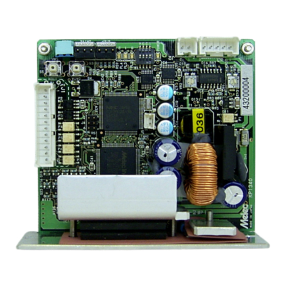
Instructions Manual 3.Name and Function of Each Section 3-1.Signal I/O Connector(J1) GDB-5311A-00 CW drive pulse signal input terminal ●Directs the motor to operate CW. CCW drive pulse signal input terminal CCW+ ●Directs the motor to operate CCW. CCW- Motor excitation stop signal input terminal M.F+... - Page 12 Instructions Manual 3-2.DC Input/Motor Output Connector(J2,J3) GDB-5311A-00 0V DC- DC input terminal DC+24V ●Power input terminal. DC power supply is connected. BLU 5 Motor output terminal ●Outputs current to drive the motor. 3-3.POWER LED POWER LED(GREEN) comes on upon inputting power.
- Page 13 Instructions Manual 3-5.Operation Section GDB-5311A-00 Option HOLD CURRENT [HOLD I.ADJ] switch ADJUSTMENT trimmer DRIVE CURRENT [DRIVE I.SEL] SELECT switch STEP ANGLE [STEP SEL] SELECT switch O.H.A LED(RED) Option LED Sub adjustment switch [DHT SEL] 16ms 150ms HOLD SWITCHING TIME SELECT switch...
-
Page 14: 4.Function Set-Up By Use
Instructions Manual 4.Function Set-up by Use 4-1.Setting MOTOR SELECT switch Erroneous setting may cause burn on the skin due to overheating of the motor. Ensure correct setting. The MOTOR SEL switch is turned to the setting corresponding to the motor in use. Set this switch with power OFF. - Page 15 Instructions Manual 4-3.Setting HOLD CURRENT ADJUSTMENT trimmer A high setting value may cause burn on the skin due to overheating of the motor. Do not select a high value beyond the required. HOLD CURRENT is set up with the HOLD I.ADJ trimmer. This sets the ratio of HOLD CURRENT to DRIVE CURRENT.
- Page 16 Instructions Manual 4-4.Setting DRIVE CURRENT SELECT switch Erroneous setting may cause burn on the skin due to overheating of the motor. Ensure correct setting. DRIVE CURRENT is set up with the DRIVE I.SEL switch. The switch is factory-set to [No.F]. (1) Set the switch No.
- Page 17 Instructions Manual 4-5.Setting HOLD SWITCHING TIME SELECT switch DRIVE/HOLD CURRENT automatic switching time is set up with the HOLD SWITCHING TIME SELECT switch. The switch is factory-set to [150ms]. (1) Set the switch2 [150ms/16ms]. Hold Switching switch2 Time 16ms 150ms 4-6.Setting Option switch At present there is not a function.
- Page 18 Instructions Manual 5.Installation 5-1.Conditions for Installation Overheating may cause fire. Mount it on a noncombustible member. Keep it away from combustibles. (1) Designed for incorporating into equipment used indoors, this product requires to be installed in the following environment: ●Indoors (where it is not exposed to direct sun).
- Page 19 ●M-3 screw (8mm or more in length): ●M-3 spring washer: ●M-3 flat washer: (1) Fix the product at the two round holes on the main body. ●Mounting example Fixing with a screw x 2 M-3 screw M-3 spring washer M-3 flat washer GDB-5311A-00 -19-...
- Page 20 Instructions Manual 6.Connection 6-1.Overview of Connection Configuration DC Power Supply 0V(GND) DC+24V MOTOR User GDB-5311A-00 Controller Twisted J2 2 1 J3 5 4 3 2 1 pair wire CCWP CCW+ CCWP CCW- +COM M.F+ M.F- R.GND R.GND O.H.A O.H.A R.GND R.GND...
- Page 21 (Surface on which the contacts are inserted) Housing for J1 〈Crimping〉 〈Wiring〉 〈Insertion〉 〈Connection〉 User Contact Housing GDB-5311A-00 for J1 Controller (0.15mm or more) Drive pulse input CCWP CCW+ Drive pulse input...
- Page 22 Also, check if the contacts are not displaced from the housing. (Surface on which the contacts are inserted) Housing for J2 Housing for J3 〔DC input Connector〕 〈Crimping〉 〈Connection〉 〈Insertion〉〈Wiring〉 GDB-5311A-00 Housing Contact for J2 Power Supply (0.3mm or more) 0V(GND) (0.3mm...
- Page 23 Instructions Manual 〔Motor output Connector〕 〈Connection〉 〈Crimping〉 〈Insertion〉 GDB-5311A-00 Housing 〈Wiring〉 for J3 Contact Leads of the motor MOTOR SEL switch (0.3mm or more) is set to [5L]. BLU 5 Blue Switch1: ON YEW 4 Yellow Motor Orange RED 2 Black 〈Connection〉...
-
Page 24: Setting Motor Select Switch
Instructions Manual 7.Confirmation of Setting and Connection 7-1.Check Points This product requires different switch setting and motor wiring depending on the motor used. Check if the switch setting and the motor wiring are correctly performed. Check Points Check Remarks Setting of STEP ANGLE Switch No. -
Page 25: 8.Maintenance And Check-Up
Instructions Manual 8.Maintenance and Check-up 8-1.Maintenance and Check-up Injury or fire is apprehended due to unexpected behavior. Do not replace fuse. Do not disassemble, repair or modify. (1) As for a maintenance inspection the engineer of the speciality shall do it. (2) We recommend that the following check-ups should be performed periodically: ●Checking for any loosened contact on the connectors. -
Page 26: Troubleshooting
Instructions Manual 8-2.Troubleshooting Trouble Check Item Assumed Cause 1. POWER LED does not ・Connection of power supply. ・Wiring error with power come on. ・Value of power voltage. supply. ・Power voltage failure. ・Driver failure. 2. The motor is not excited. ・Connection of the motor to ・Wiring error with the motor (It can be easily the driver. -
Page 27: 9.Storing And Disposal
Instructions Manual 9.Storing and Disposal 9-1.Storing (1) Keep the product in the following environment: ●Indoors (where it is not exposed to direct sun). ●Where ambient temperature and humidity are controlled within the range set out in the specifications. ●Where there is no corrosive or inflammable gas. ●Where it can be protected from dust, salt or iron powder. -
Page 28: 10.Specifications
Instructions Manual 10.Specifications 10-1.General Specifications DC+24V *1 (Ripple voltage P-P 2.0V or less) ● Rated input current : 〔DRIVE I.SEL ⇒ No.F set up〕 Supply Power at DRIVE DC+24V: 1.5A ● Rated input current : 〔HOLD I.ADJ ⇒ Approx. 40% set up〕 at HOLD DC+24V: 0.3A ●DRIVE CURRENT... - Page 29 Instructions Manual 10-2.I/O Signal (1) Example Circuit Connection -29-...
- Page 30 Instructions Manual (2) Drive pulse input(CW, CCW) ① Operating current range : 9mA~27mA The photo-coupler turns on with inter-terminal voltage of 3.1 V~5.5 V. (Photo-coupler diode V ≒ 1.6 V) ② Timing chart CCWP [To the line driver 26LS31] CW + (CCW +) t1≧0.5μs,...
- Page 31 Instructions Manual (3) Motor excitation stop input(M.F) Deterioration of the holding power with the motor may cause breakage of the machine or injury. Check safety before inputting. ① Operating current range : 4mA~5.3mA The photo-coupler turns on with inter-terminal voltage of 19.1 V~25.1 V. (Photo-coupler diode V ≒...
- Page 32 Instructions Manual (4) Phase signal output(P.O) ① Output current a. I ≦6mA, V <5V CE(sat) b. I ≦2mA, V ≦0.6V CE(sat) ≦30V ● In case of the excitation home position, the signal is output. (photo-coupler ON) ● In case of simultaneously using P.O signal and C.S signal, input C.S signal while P.O signal is being output to switch the step angle.
- Page 33 Instructions Manual (5) Overheat alarm signal output(O.H.A) Overheating may cause fire. Stop operation upon output of this signal. ① Output current a. I ≦6mA, V <5V CE(sat) b. I ≦2mA, V ≦0.6V CE(sat) ≦30V ● Please use overheat alarm signal output(O.H.A)without fail. ●...
-
Page 34: (6) Step Angle Switch Input(C.s
Instructions Manual (6) Step angle switch input(C.S) ① Operating current range : 4.0mA~5.3mA The photo-coupler turns on with inter-terminal voltage of 19.1 V~25.1 V. (Photo-coupler diode V ≒ 1.1 V) ● Step angle division is switched to 1/20 divisions with the photo-coupler ON. The setting for the STEP ANGLE SELECT switch is ignored. -
Page 35: Dimensions
Instructions Manual 10-3.Dimensions (Unit:mm) -35-... -
Page 36: Applicable Motors
Instructions Manual 10-4.Applicable Motors ●5-phase stepping motors of following table. Setting Basic Setting MOTOR SEL Torque Data Current Applicable Motors Angle DRIVE I.SEL Fig. No. (A/phase) switch (°) switch No. switch1 Oriental Motor Co., Ltd. Fig.1 PK543-A(B) Fig.2 PK544-A(B) 0.72 0.75 Fig.3 PK545-A(B) -
Page 37: Torque Characteristics
Instructions Manual 10-5.Torque Characteristics (1) Representations in the torque characteristics table are made in terms of the -1 motor rotation (s ) vs. torque (N・m). -1 Motor rotation (s ) and drive pulse frequency (Hz) are converted as follows: 360° -1... - Page 38 Instructions Manual -38-...
- Page 39 Technical Service TEL.(042)664-5382 FAX.(042)666-5664 E-mail s-support@melec-inc.com Sales and Service TEL.(042)664-5384 FAX.(042)666-2031 URL:http://www.melec-inc.com Melec Inc. Control equipment marketing department 516-10,Higashiasakawa-cho,Hachioji-shi,Tokyo 193-0834,Japan This Operating Manual is subject to change without prior notice ロロロロ for the purpose of product improvement.
Need help?
Do you have a question about the GDB-5311A-00 and is the answer not in the manual?
Questions and answers