Table of Contents

Related Manuals for Melec GD-5410v1


Summary of Contents for Melec GD-5410v1
- Page 1 5-phase Stepping Motor Driver GD-5410v1 Instructions Manual (For designers' use) Please ensure to read and understand this Instructions Manual before using the product. Please keep this Instructions Manual at hand MN03 8 0-1...
- Page 2 Instructions Manual Introduction This Instructions Manual describes the safe and proper method of handling '5-phase Stepping Motor Driver GD-5410v1' with emphasis on the specifications, assuming that our readers are engaged in designing of control devices incorporating stepping motors. Please ensure to read and understand this Instructions Manual before using the product.
- Page 3 GD-5410v1 Instructions Manual Descriptions in this manual on safety matters: This product must be operated and used properly. Otherwise, or when it is operated and used erroneously, unforeseen accidents may occur, causing physical injuries or property damages. Majority of these accidents can be avoided if you are well informed of hazardous circumstances in advance.
-
Page 4: Table Of Contents
GD-5410v1 Instructions Manual Introduction Descriptions in this manual on safety matters: CONTENTS PAGE 1. Safety 1-1. Safety Precautions 1-2. Safety Information for Handling 2. Overview 2-1. Characteristics 2-2. Product Configuration 2-3. Appearance 3. Name and Function of Each Section 3-1. Signal I/O Connector(J1)... - Page 5 GD-5410v1 Instructions Manual PAGE 8. Maintenance and Check-up 8-1. Maintenance and Check-up 8-2. Troubleshooting 9. Storing and Disposal 9-1. Storing 9-2. Disposal 10. Specifications 10-1. General Specifications 10-2. Conforming to Europe standards and UL standards 10-3. I/O Signal (1) Example Circuit Connection (2) Drive pulse input (CW,CCW) (3) Motor excitation stop input (M.F)
-
Page 6: 1.Safety
GD-5410v1 Instructions Manual 1.Safety 1-1.Safety Precautions WARNING (1) This product is not designed or manufactured for application for equipment requiring high level of reliability such as equipment related to nuclear energy, aeronautics-related equipment, automobiles, ships, medical appliances directly handling the human body and equipment that might seriously affect properties. -
Page 7: Safety Information For Handling
GD-5410v1 Instructions Manual 1-2.Safety Information for Handling ●Overall: WARNING Do not touch the driver during operation. Failure to do so may cause electric shock. WARNING indicate terminals on which power voltage is applied. Do not touch such terminals while inputting power and while POWER LED is on. - Page 8 GD-5410v1 Instructions Manual CAUTION Erroneous connection may result in breakage of the motor or the driver. Correctly connect the motor wiring. ●When setting up the STEP ANGLE SELECT switch: CAUTION Erroneous setting may cause breakage of the machine or injury due to unexpected rotation of the motor.
- Page 9 GD-5410v1 Instructions Manual ●When inputting the motor excitation stop (M.F) signal: CAUTION Deterioration of the holding power with the motor may cause breakage of machine or injury. Check safety before inputting. ●When installing: WARNING Overheating may cause fire. Mount it on a noncombustible member.
- Page 10 GD-5410v1 Instructions Manual ●When the overheat alarm (O.H.A) LED comes on WARNING Overheating may cause fire. Stop operation when this LED comes on. ●When performing maintenance and checking: WARNING Only qualified personnel are allowed to perform maintenance and checking. Failure to do so may cause electric shock.
-
Page 11: 2.Overview
Instructions Manual 2.Overview 2-1.Characteristics GD-5410v1 is a driver for a 5-phase stepping motor with single-phase 100-115V input. Ten step angles can be selected from angles ranging from a 1/1 division to a 1/800 division of the basic angle. HOLD CURRENT and DRIVE CURRENT can be set up. - Page 12 GD-5410v1 Instructions Manual 3.Name and Function of Each Section 3-1.Signal I/O Connector(J1) GD-5410v1 CW drive pulse signal input terminal ●Directs the motor to operate CW. CCW drive pulse signal input terminal CCW+ ●Directs the motor to operate CCW. CCW- Motor excitation stop signal input terminal M.F+...
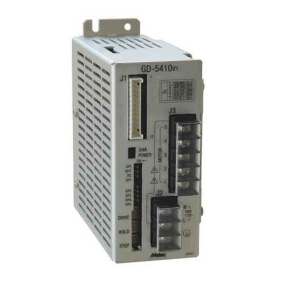
- Page 13 GD-5410v1 Instructions Manual 3-2.AC Input/Motor Output Terminal Block(J2,J3) WARNING Do not touch the driver during operation. Failure to do so may cause electric shock. GD-5410v1 Motor output terminal ●Outputs current to drive the motor. 100- AC input terminal 115V~ ●Power input terminal.
- Page 14 GD-5410v1 Instructions Manual 3-5.Operation Section WARNING Do not touch the driver during operation. Failure to do so may cause electric shock. GD-5410v1 OHA LED(RED) POWER LED(GREEN) POWER PULSE INPUT TYPE SELECT switch (SPI) [1P - 2P] [1s - 150ms] HOLD SWITCHING TIME SELECT switch (DHT)
-
Page 15: 4.Setting
GD-5410v1 Instructions Manual 4.Setting 4-1.Setting STEP ANGLE SELECT switch CAUTION Erroneous setting may cause breakage of the machine or injury due to unexpected rotation of motor. Ensure correct setting. The step angle is set up with the 〔STEP〕 switch. Set the 〔STEP〕switch No. to the step angle required. - Page 16 GD-5410v1 Instructions Manual 4-2.Setting HOLD CURRENT SELECT switch CAUTION A high setting value may cause burn on the skin due to overheating of the motor. Do not select a high value beyond the required. HOLD CURRENT is set up with the 〔HOLD〕switch.
- Page 17 GD-5410v1 Instructions Manual 4-3.Setting DRIVE CURRENT SELECT switch CAUTION Erroneous setting may cause burn on the skin due to overheating of the motor. Ensure correct setting. DRIVE CURRENT is set up with the 〔DRIVE〕switch. (1) Set the 〔DRIVE〕switch No. to the setting specified in the table '10-5.Applicable Motors'.
- Page 18 GD-5410v1 Instructions Manual 4-4.Setting HOLD SWITCHING TIME SELECT switch DRIVE/HOLD CURRENT automatic switching time is set up with the 〔DHT〕switch. (1) Set the 〔DHT〕switch. Hold Switching Time 150ms (Factory Setting) 4-5.Setting ROTATE CHARACTERISTIC SELECT switch Please use it with OFF.
- Page 19 GD-5410v1 Instructions Manual 4-6.Setting PULSE INPUT TYPE SELECT switch CAUTION Erroneous setting may cause breakage of the machine or injury due to unexpected rotation of motor. Ensure correct setting. 2-pulse input method / 1-pulse input method are set up by the 〔SPI〕switch.
- Page 20 GD-5410v1 Instructions Manual 5.Installation 5-1.Conditions for Installation WARNING Mount it on a noncombustible member. Keep it away from combustibles. Overheating may cause fire. (1) Designed for incorporating into equipment used indoors, this product requires to be installed in the following environment: ●...
- Page 21 GD-5410v1 Instructions Manual 5-2.Mounting Method The following items are required: ● M-4 screw (8mm or more in length): ● M-4 spring washer: ● M-4 flat washer: (1) Temporarily fix the product at the round hole. (2) Fix the product at the three cutouts.
- Page 22 GD-5410v1 Instructions Manual 6.Connection 6-1.Overview of Connection Configuration User GD-5410v1 Twisted controller pair wire CCWP CCW+ CCWP CCW- +COM M.F+ M.F- P.O+ R.GND P.O- O.H.A O.H.A+ R.GND O.H.A- +COM C.S+ Motor C.S- Single-phase 100-115V Single-phase 100-115V Protective earth (O.75mm or more)
- Page 23 GD-5410v1 Instructions Manual 6-2.Connecting Signal I/O Connector(J1) The following items are required: ● Housing for J1 (51103-1200:Molex): One unit (accessory) ● Contact for J1 (50351-8100:Molex): 12 contacts (accessories) ● Manually operated crimping tool for AWG28-22(57295-5000:Molex): One unit (1) Crimp the contact to the cable used for wiring.
- Page 24 GD-5410v1 Instructions Manual 6-3.Connecting AC Input/Motor Output Terminal Block(J2,J3) WARNING Turn the main power OFF. Failure to do so may cause electric shock. WARNING Securely ground the protective earth Failure to do so may cause electric shock. WARNING Do not force the power line or the motor line to be bent or pulled or pinched.
- Page 25 GD-5410v1 Instructions Manual 〔Protective earth terminal ・ AC input terminal〕 〈Crimping〉 GD-5410v1 〈Connection〉 〈Wiring〉 Crimping terminal NEUTRAL 100- Single-phase 100-115V 115V~ LIVE Protective earth Protective earth terminal terminal for the equipment (PE) ● the protective earth terminal of the equipment (PE).
- Page 26 GD-5410v1 Instructions Manual 〔Motor output terminal〕 〈Crimping〉 GD-5410v1 〈Connection〉 〈Wiring〉 Crimping terminal Leads of the motor Green/Brown White/Orange Motor Black/Yellow Red/Gray Violet/Blue 〈Crimping〉 〈Connection〉 〈Wiring〉 GD-5410v1 Crimping terminal Leads of the motor Blue Motor Orange Green Black ● Color indications for the motor crimping terminals (1~5) represent colors of the leads of the motor.
- Page 27 GD-5410v1 Instructions Manual 6-4.Inputting Power WARNING Do not contact with a wet hand. Doing so may cause electric shock. WARNING indicate terminals on which power voltage is applied. Do not touch such terminals while inputting power and while POWER LED is on.
-
Page 28: Setting Step Angle Select Switch
GD-5410v1 Instructions Manual 7.Confirmation of Setting and Connection 7-1.Check Points (1) This product requires different switch setting and motor wiring depending on the motor used. Check if the switch setting and the motor wiring are correctly performed. (3) Check if the terminal block covers are fixed on J2 and J3. -
Page 29: 8.Maintenance And Check-Up
GD-5410v1 Instructions Manual 8.Maintenance and Check-up 8-1.Maintenance and Check-up WARNING Only qualified personnel are allowed to perform maintenance and checking. Failure to do so may cause electric shock. WARNING Do not contact with a wet hand. Doing so may cause electric shock. -
Page 30: Troubleshooting
GD-5410v1 Instructions Manual 8-2.Troubleshooting Trouble Check Item Assumed Cause 1. POWER LED does not ・Connection of power supply. ・Wiring error with power supply. come on. ・Value of power voltage. ・Power voltage failure. ・Driver failure. 2. The motor is not excited. -
Page 31: 9.Storing And Disposal
GD-5410v1 Instructions Manual 9.Storing and Disposal 9-1.Storing (1) Keep the product in the following environment: ● Area that is free of explosive, corrosive or inflammable gas ● Indoors (Area not exposed to direct sunshine) ● Area that ambient temperature and humidity are controlled within the range set out in the specifications ●... -
Page 32: 10.Specifications
GD-5410v1 Instructions Manual 10.Specifications 10-1.General Specifications Single-phase 100-115V(50/60Hz) *1 ●Rated power at DRIVE: 〔DRIVE I.SEL ⇒ No.F set up〕*2 Supply Power AC100V : 2.6A AC115V : 2.6A ●Rated power at HOLD: 〔DRIVE I.SEL ⇒ No.F, HOLD I.SEL ⇒ 40% set up〕... - Page 33 GD-5410v1 Instructions Manual 10-2.Conforming to Europe standards and UL standards This product conducted the validation test of low voltage directive and EMC directive with TÜV(TÜV Japan) for self-declaration of the CE making. (1) Safety standards EN 61800-5-1 UL 61800-5-1 ●Low voltage directive This product is designed for use as a built-in component.
- Page 34 GD-5410v1 Instructions Manual 10-3.I/O Signal (1) Example Circuit Connection (J1) Example connection GD-5410v1 of the user controller 300Ω 26LS31 Photo-coupler CCWP CCW+ 300Ω CCWP CCW- 26LS31 Photo-coupler +24V +COM M.F+ 1.3kΩ M.F- Photo-coupler P.O+ Photo-coupler R.GND P.O- Photo-coupler O.H.A O.H.A+ Photo-coupler R.GND...
- Page 35 GD-5410v1 Instructions Manual (2) Drive pulse input(CW, CCW) ① Operating current range : 5mA~14mA (J1) The photo-coupler turns on with GD-5410v1 inter-terminal voltage of 3.1 V~5.5 V. 300Ω (Photo-coupler diode V ≒ 1.5 V) ② Timing chart Photo-coupler CCW+ 300Ω...
- Page 36 GD-5410v1 Instructions Manual (3) Motor excitation stop input(M.F) CAUTION Deterioration of the holding power with the motor may cause breakage of the machine or injury. Check safety before inputting. ① Operating current range : 2.6mA~19.5mA GD-5410v1 (J1) The photo-coupler turns on with M.F+...
- Page 37 GD-5410v1 Instructions Manual (4) Phase signal output(P.O) ① Output current a. I ≦6mA, V <2V b. I ≦2mA, V 0.6V GD-5410v1 CE(sat)< (J1) ≦30V P.O+ P.O- Photo-coupler ● In case of the excitation home position, the signal is output. (photo-coupler ON) ●...
- Page 38 GD-5410v1 Instructions Manual (5) Overheat alarm signal output(O.H.A) WARNING Overheating may cause fire. Stop operation upon output of this signal. WARNING Overheating may cause fire. Stop operation when this LED comes on. ① Output current a. I ≦6mA, V <2V (J1) b.
-
Page 39: (6) Step Angle Switch Input(C.s
GD-5410v1 Instructions Manual (6) Step angle switch input(C.S) ① Operating current range : 2.6mA~19.5mA The photo-coupler turns on with GD-5410v1 (J1) inter-terminal voltage of 4.5V~26.4V. (Photo-coupler diode V ≒ 1.1 V) C.S+ 1.3kΩ C.S- Photo-coupler ● Step angle division is switched to 1/20 divisions with the photo-coupler ON. -
Page 40: Dimensions
GD-5410v1 Instructions Manual 10-4.Dimensions (Unit:mm) GRN/BRN WHT/ORN BLK/YLW RED/GRY VIO/BLU (14.5) 124.5 14.5 49.5 (55.5) -40-... - Page 41 GD-5410v1 Instructions Manual 10-5.Applicable Motors ● GD-5410v1 can drive a 5-phase stepping motors of 0.75 - 1.8A/phase. Basic Current DRIVE Torque Data ORIENTAL MOTOR CO., LTD. Angle (A/phase) switch switch switch Fig. No. (°) Fig.1 PK543-A(B) □42mm PK544-A(B) 0.72 0.75 Fig.2...
-
Page 42: Torque Characteristics
GD-5410v1 Instructions Manual 10-6.Torque Characteristics (1) Representations in the torque characteristics table are made in terms of the -1 motor rotation speed (s ) vs. torque (N・m). -1 Motor rotation speed (s ) and drive pulse frequency (Hz) are converted as follows: 360°... - Page 43 GD-5410v1 Instructions Manual Fig.1 Fig.2 DRIVE = No.4 DRIVE = No.4 GD-5410v1 GD-5410v1 OP1,OP2 = ON,ON OP1,OP2 = ON,ON PK543-A(B) PK544-A(B) AC100V 0.75A/PHASE 0.75A/PHASE AC100V DRIVER INPUT CURRENT(A) DRIVER INPUT CURRENT(A) TORQUE(N・m) TORQUE(N・m) 0.25 0.25 HOLD 40% = 0.063 N・m HOLD 40% = 0.074 N・m...
- Page 44 GD-5410v1 Instructions Manual Fig.7 Fig.8 DRIVE = No.F DRIVE = No.4 GD-5410v1 GD-5410v1 OP1,OP2 = ON,ON OP1,OP2 = ON,ON PKP546N18A(B)2 PK564-A(B) AC100V 1.8A/PHASE 0.75A/PHASE AC100V DRIVER INPUT CURRENT(A) DRIVER INPUT CURRENT(A) TORQUE(N・m) TORQUE(N・m) HOLD 40% = 0.24 N・m HOLD 40% = 0.20 N・m...
- Page 45 GD-5410v1 Instructions Manual Fig.13 Fig.14 DRIVE = No.B DRIVE = No.B GD-5410v1 GD-5410v1 OP1,OP2 = ON,ON OP1,OP2 = ON,ON PK596-A(B) PK599-A(B) AC100V 1.4A/PHASE 1.4A/PHASE AC100V DRIVER INPUT CURRENT(A) DRIVER INPUT CURRENT(A) TORQUE(N・m) TORQUE(N・m) 10.0 HOLD 40% = 1.02 N・m HOLD 40% = 2.06 N・m...
- Page 46 GD-5410v1 Instructions Manual Fig.19 DRIVE = No.B GD-5410v1 OP1,OP2 = ON,ON 103F7853-8241(8211) AC100V 1.4A/PHASE DRIVER INPUT CURRENT(A) TORQUE(N・m) HOLD 40% = 0.77 N・m PULLOUT TORQUE DRIVER INPUT CURRENT 0.01 MOTOR ROTATION SPEED(s 6000 MOTOR ROTATION SPEED(r/min) 自起動記 デー デー 横...
-
Page 47: The Main Parts Which Revised By This Manual
GD-5410v1 Instructions Manual The main parts which revised by this manual Parts Content 【R1】 Correction of errors ・Operating current range : 9mA~27mA → 5~14mA ・VF≒1.6V → 1.5V -47-... - Page 48 Technical Service TEL.(042)664-5382 FAX.(042)666-5664 E-mail s-support@melec-inc.com Sales and Service TEL.(042)664-5384 FAX.(042)666-2031 URL:http://www.melec-inc.com Melec Inc. Control equipment marketing department 516-10,Higashiasakawa-cho,Hachioji-shi,Tokyo 193-0834,Japan This Operating Manual is subject to change without prior notice for the purpose of product improvement. 1812...
Need help?
Do you have a question about the GD-5410v1 and is the answer not in the manual?
Questions and answers