Table of Contents
Advertisement
Quick Links
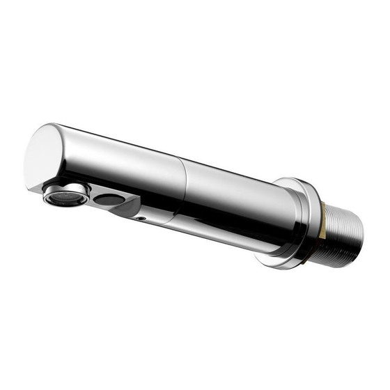
Sensorflow 21 compact panel
mounted 150 & 230 reach spouts
Ø10
650mm
Ø15
Ø10
570mm
Ø15
Ø15
103
86
Ø15
Important:
1. Electrical connection: mains electric powered versions of these
products must be connected to a continuous permanent power supply.
2. Sensor protector: this black-out lens cover should only be removed
from the sensor after completing installation & at least 20 seconds
after powering up.
See page 3 for more details.
BEFORE CONNECTION, FLUSH WATER THROUGH PIPEWORK TO REMOVE
ALL DEBRIS ETC. WHICH COULD DAMAGE THE VALVE MECHANISM
INSTALLER:
After installation please pass this instruction booklet to user
Ø50
M33 x 1.5
max.30
Ø50
M33 x 1.5
max.30
Ø15
61
Ø15
IMPORTANT
Ø38
150
Ø38
230
40
116
INSTALLATION
INSTRUCTIONS
150 Reach:
A4845AA,
A4846AA &
A4847AA
230 Reach:
A4848AA,
A4849AA &
A4850AA
67
Advertisement
Table of Contents

Subscribe to Our Youtube Channel
Related Manuals for Armitage Shanks Sensorflow 21 A4845AA


Summary of Contents for Armitage Shanks Sensorflow 21 A4845AA
- Page 1 INSTALLATION Sensorflow 21 compact panel INSTRUCTIONS mounted 150 & 230 reach spouts Ø50 Ø10 M33 x 1.5 150 Reach: A4845AA, Ø38 A4846AA & 650mm A4847AA Ø15 max.30 Ø50 Ø10 M33 x 1.5 230 Reach: Ø38 A4848AA, A4849AA & 570mm A4850AA Ø15 max.30 Ø15...
-
Page 2: Table Of Contents
TABLE OF CONTENT IMPORTANT PRE-INSTALLATION NOTES ........3 PRODUCT BOX CONTENTS ............4 SUPPLY CONDITIONS ..............5 WATER REGULATIONS ..............5 INSTALLATION GUIDE ..............6 MOUNTING ......................6 PLUMBING OVERVIEW ..................7 ELECTRICAL CONNECTION ................9 TAP OPERATION ................14 SENSOR RANGING ................ 15 OUTLET OPTIONS ................ -
Page 3: Important Pre-Installation Notes
IMPORTANT PRE-INSTALLATION NOTES MAINS ELECTRICAL POWER SUPPLY Mains powered Sensor Operated Products must be connected to a (fused / switched) continuous permanent power supply. Connection to an interrupted power supply intended to stop electrical consumption in an unused facil- ity, may adversely affect this sensor product and is therefore not recommended. Each time the power supply is reinstated the product briefly enters reprogramming mode. -
Page 4: Product Box Contents
PRODUCT BOX CONTENTS 1x copper inlet pipe 1x Sensorflow 21 compact spout with integral sensor Regulated PCA outlet pre-fitted. See section 8 2x Couplers G 1/2“ female thread to 15 mm compression 1x Spout mounting kit 1x Outlet key 1x Flow straightener moulding 1x Velcro... -
Page 5: Supply Conditions
WATER REGULATIONS The fittings covered by this installation and maintenance instruction should be installed in accordance with the water regulations published in 1999*, therefore Armitage Shanks would strongly recommend that these fittings are installed by a professional installer *A guide to the Water Supply (Water Fittings) Regulations 1999 and the Water Byelaws 2000, Scotland is published by WRAS (Water Regulations Advisory Scheme) Fern Close, Pen-y-Fan Industrial Estate, Oakdale, Newport, NP11 3EH. -
Page 6: Installation Guide
INSTALLATION GUIDE Before connection, flush water through pipe-work to remove all debris etc. to prevent damage to the valve mechanism. THEN ENSURE WATER SUPPLIES HAVE BEEN ISOLATED. Mounting DRILL PANEL HOLE Ø35 MIN, Ø40 MAX INSTALLATION HEIGHT: we recommend the spout outlet be positioned approximately 150-200mm above the basin or worktop (which ever is higher). -
Page 7: Plumbing Overview
INSTALLATION GUIDE continued… Spout inlet pipe Ø10mm Plumbing Overview Once the spout has been secured to the panel, consideration should be given to installing & positioning of the inline valves. Inlet elbow A typical plumbing installation example is shown here. The water is being supplied from 15 to 10mm below, but can be from any direction. - Page 8 INSTALLATION GUIDE continued… 5. To fit inlet elbow cont: Slip the larger compression nut & olive onto a short length of Ø15mm supply pipe. Push the supply pipe into the elbow up to the shoulder. Slide the olive up to the elbow & tighten the compression nut with a 24mm A/F spanner.
-
Page 9: Electrical Connection
INSTALLATION GUIDE continued… Electrical connection Connection of this product to mains power supply should be undertaken by a competent person and should conform to IEE Wiring Regulations black Orientation & position of solenoids, and PSU (Power Supply Unit) case can differ from installa- tion to installation. - Page 10 INSTALLATION GUIDE continued… Electrical connection continued… ENSURE MAINS POWER SUPPLY IS SWITCHED OFF BEFORE COMMENCING MAINS AC 13. Open the PSU case by unscrewing 4x PLUS LINK(S) posi-drive screws. 14. The lid & seal should separate from the PSU case. 15.
- Page 11 Each type of PSU is identified by this coloured dot system: MAINS MAINS AC PLUS LINK(S) BLUE LINK BATTERY GREEN MAINS AC -SOLO BATTERY -SOLO 6V Lithium CR-P2 GREEN 230 V 24. Remove the pre-split grommet from the PSU lid. Slide the grey sensor cable into this grommet.
- Page 12 INSTALLATION GUIDE continued… Electrical connection continued… 28. Mains power cable (not supplied) should be flexible 3A rated (multi-strand) 2 core cable. Prepare the cable for connection into the PCB by carefully stripping back the outer sheath by about 100mm. Strip the wire ends back by about 5mm.
- Page 13 INSTALLATION GUIDE continued… Electrical connection continued… A pair of self-adhesive Velcro-type pads are provided. Attach one to the side of the PSU case & the other to a suitable location on the rear of the mounting panel. Ensure the selected location does not stretch/stress the cables.
-
Page 14: Tap Operation
INSTALLATION GUIDE continued… Electrical connection continued… Example above of an installation where PSUs are all mains versions. Sensor taps stickers: To complete the installation, 2 stickers are provided which can be stuck onto a wall or panel in close proximity to this product to advise the end user that this product sensor operated. -
Page 15: Sensor Ranging
SENSOR RANGING If the Sensor detects a strong reflection (or similar), the spout will turn on and off intermittently with no one present (Pulsing On / Off). In the unlikely event that this does happen, the Sensing Range must be reduced. -
Page 16: Outlet Options
OUTLET OPTIONS This product comes with two outlets one fitted & the second supplied in a bag. The product is factory fitted with a laminar PCA regulated outlet which is secured within an anti-vandal (AV) housing. Unregulated full-flow flow straightener 0.5 bar l/min (SUPPLIED LOOSE) -
Page 17: Hygiene Flush (Automatic)
Maintenance continued… • Remove the 3 screws holding the coil. • Lift off the coil assembly. • Locate the diaphragm (inside the valve body). • Clean out the pilot hole(s) – use a thin gauge fuse wire (or similar). If diaphragm is damaged it should be replaced. •... -
Page 18: Isolating Valve
Maintenance continued… A brief summary of how to navigate the programming unit is as follows: Handunit ON Navigate to Menu 4 PARAMETER SENSOR 2013 (Enter) MENU 4.1 HAND-WASH (Enter) AUTO-RINSE FREQUENCY: OFF ARROW UP (To required Delay time) (Enter). Recommended: 6 or 12 hours. AUTO-RINSE DURATION: (15 sec default) ARROW UP or DOWN (To required Run Time). -
Page 19: Spare Parts
SPARE PARTS For more information on spare parts why not visit our spare website: fast www.fastpart-spares.co.uk. Or contact customer care... -
Page 20: Cleaning Chrome Surfaces
0870 122 8822 This right is therefore reserved to vary specification without notice. AFTER SALES NON RESIDENTIAL FAX 0870 122 8282 Armitage Shanks is adivision of Ideal Standard (UK) Ltd E-MAIL Armitage Shanks aftersalesnonresidential@idealstandard.com The Bathroom Works, National Aveneu 0116 / A 866 817...
Need help?
Do you have a question about the Sensorflow 21 A4845AA and is the answer not in the manual?
Questions and answers