Table of Contents
Advertisement
Quick Links
Advertisement
Table of Contents

Subscribe to Our Youtube Channel
Related Manuals for Xilica Audio Design NeuPanel Mini K1


Summary of Contents for Xilica Audio Design NeuPanel Mini K1
- Page 1 NEUPANEL MINI User Manual...
- Page 2 Important Safety Information 1. READ THESE INSTRUCTIONS All the safety and operating instructions should be read before the product is operated. 2. KEEP THESE INSTRUCTIONS The safety and operating instructions should be retained for future reference. 3. HEED ALL WARNINGS All warnings on the product and in the operating instructions should be adhered to.
-
Page 3: Table Of Contents
Table of Contents What’s in the box NeuPanel Mini series models Hardware descriptions and functions Hardware device connection a. To network b. To mains power Install Xilica Designer software a. Windows installation b. Mac installation Xilica Designer’s Network View a. Device network status b. -
Page 4: What's In The Box
NeuPanel: Getting started What’s in the Box • NeuPanel series wall control device • Mounting screws (color specific to wall control color) • Surface mount back box (NeuPanel mini devices can be flush or surface mounted) • External power supply What you need to Provide • Mac or PC computer with a processor 1GHz or higher • Windows 7 or higher • Mac OSX • 500 MB of free space • 1 GB graphics card • 4 GB of RAM • External power supply is included but it is recommended to use a PoE router/switch • Ethernet cable (Cat5/6) Getting Help... -
Page 5: Neupanel Mini Series Models
NeuPanel:Model variants The Xilica NeuPanel Mini wall controls come in five different configurations. Please note that the NeuPanel series is not compatible with Solaro series DSP. NeuPanel Mini K1 Control any single value change, including: gains, threshold, frequency, etc. NeuPanel Mini K4 Control any four-value changes, including: gains, threshold, frequency, etc. -
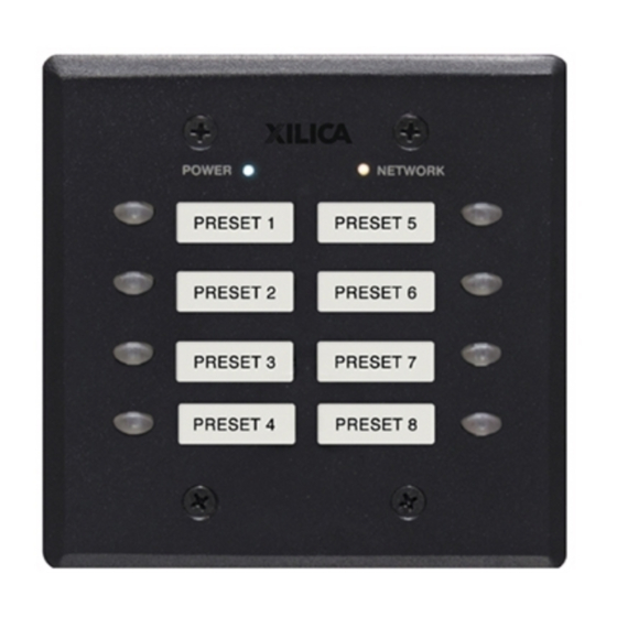
Page 6: Hardware Descriptions And Functions
NeuPanel:Hardware device Power status LED When the device is Powered On, this indicator will light blue. Network LED When the device has an Ethernet cable connected, the Network status LED will light orange once the processor initializes. If there is no Ethernet cable attached, this light will remain off. Note: When the Network status LED is on, it does not indicate that you have established a Network connection - only that an Ethernet cable is connected to the processor. Proper Network connection is displayed in Xilica Designer’s Network view. For more detail please refer to ‘Network view’ on Page 12. - Page 7 NeuPanel:Hardware device Ethernet connector Connect to the network using an Ethernet Cat 5/6 cable (and power if using Power over Ethernet (PoE). The port is a standard RJ45 (Ethernet). Power supply connector Power the device using the included external power supply. If you are sending Power over Ethernet (PoE), the external power supply is not needed. IP Reset button Reset the IP Address by following the IP Reset Procedure. (Refer to connection troubleshooting: Page 13) USB connector Not used. (Xilica use only)
- Page 8 NeuPanel:Device connection Initial Device Connectivity: Xilica processors and control devices run on a network based infrastructure and are set up and controlled by a host computer via Ethernet using the Xilica Designer software. A network connection can be made between the computer and processor using: a) DHCP enabled Router or Server/Router combination (Recommended) b) or a non-DHCP enabled network connection (i.e. PoE switches). Note: DHCP enabled Router/switch gear should be turned on first, with all Ethernet cables connected to the hardware prior to powering on the Hardware. This will allow for proper handling of IP address distribution to the Hardware.
-
Page 9: To Mains Power
NeuPanel:Device connection All wired connections use a standard RJ45 Cat 5/6 (Ethernet) connection. Xilica Designer and XTouch Applications can also be connected via a Wi-Fi connection, but this is not recommended. Standard RJ45 cable A) DHCP enabled router or server/router combination (Recommended) With DHCP enabled routers and servers, the mini wall control will automatically obtain the IP address upon power up and connection. -
Page 10: Windows Installation
NeuPanel: Xilica Designer installation Xilica Designer Software Installation Windows Platform Installation With the Xilica USB thumb drive included with your Xilica product, transfer the files from the USB to a memorable location on your computer. Alternatively, you can download the latest version of the Xilica Designer software from the Xilica website (www.xilica.com). It is highly recommended that you make sure you are using the latest version. -
Page 11: Mac Installation
NeuPanel: Xilica Designer installation Mac OSX Platform Installation With the Xilica USB thumb drive included with your Xilica product, transfer the files from the USB to a memorable location on your computer. Alternatively, you can download the latest version of the Xilica Designer software from the Xilica website (www.xilica.com) Double click on the ‘XilicaDesigner.mpkg.’ file saved on your computer. OSX will display an installation dialogue. Read and follow each step carefully, then click ‘continue’ to proceed. When the installation is successful, the following dialogue will be displayed. -
Page 12: Device Network Status
NeuPanel:Network view Launch the Xilica Designer Software Upon launching the Xilica Designer software, a start-up window will pop up. You may select a ‘New Design Project’, ‘Open Design Project’, ‘Start Network View’ or ‘Start Dante View’. (Network and Dante View are also available within the Xilica Designer software). Select ‘Start Network View’. -
Page 13: Connection Troubleshoot
NeuPanel: Connection troubleshoot Connection Problems? Yellow Network indicator In Xilica Designer’s Network View, if there is a Yellow network connection indicator at the top left of the device, the device is connected and online, but Not operational. To assist in identifying the problem, hover your cursor over the device network indicator and a pop-up message will identify the problems it has detected. - Page 14 NeuPanel: Connection troubleshoot Software network problems continued Device Not Ready If the pop-up message shown says Device Not ready, please wait a few minutes until the device is ready. The device should then connect and the indicator turn Green. Device Schematic Not Ready The device has already been loaded with a DSP design.
-
Page 15: Manual Assignment Of Ip Addresses
NeuPanel: Manual IP Address Manual Assignment of IP Addresses for devices There are applications that require the IP address to be manually assigned (the same solution may apply to some connection issues). To manually assign IP addresses, In the Network View, right click the device and select ‘Device Setup’. In the ‘Network’... - Page 16 NeuPanel: Manual IP Address Assigning a Static IP address for your computer The following process applies to manually assigning a unique static IP address to your computer. Windows platform In the start menu, select control panel. Click ‘Network and Internet’. Under the heading ‘Network and sharing center’, select ‘View network status and tasks’...
- Page 17 NeuPanel: Manual IP Address Mac p latform From the Apple menu, select System preferences. Select ‘Network’. From the sidebar, select the network interface you are using. 3. Then click ‘Advanced...’ 4. In the TCP/IP tab, set Configure IPv4 to ‘Manually’ using the drop down menu. Enter a static IP address in the IPv4 Address field. Set up your computer’s IP address to be 192.168.1.X where X can be any value from 0-255, but unique from other device IP addresses. Use the following settings for your computers static address: IP address: 192.168.1.X (X is any value from 0-255 but unique from other device IP addresses) Subnet mask: 255.255.255.0 Router: 192.168.1.1...
-
Page 18: Firmware Upgrade
NeuPanel: Firmware upgrade Firmware Upgrade It is strongly recommended that you check the Xilica website (www.xilica.com) frequently for the latest software and firmware versions, as these updates may contain critical bug fixes and new features. Note: Using an older version of software with a newer firmware or newer software with an older firmware will work but some of the features may not be available and bugs could exist. - Page 19 NeuPanel: Firmware upgrade Step-by-Step Firmware Upgrade Guide The hardware device must be connected and operational (Green indicator) before upgrading the firmware. Download the latest firmware version for your device from our website. (www.xilica.com) In Network View, all the units on the network are displayed. The network connection indicator is displayed at the top left of each device.
- Page 20 NeuPanel: Firmware upgrade Click ’Ok’ to select a file from your computer. Then navigate to the appropriate firmware file that you have downloaded from our website. Select the correct file and click “Open”. (Ex. A Neutrino A1616-N is being updated, so the firmware file at the time of this QSG is Neutrino_5_4_2.img.) A status bar in the device window will monitor the Firmware upgrade progress. When the Firmware has been uploaded to the device, the device will automatically restart and update its internal data. This may take several minutes. During this period, the device network indicator will turn RED and appear offline. DO NOT POWER OFF THE DEVICE as the device is performing self-initialization. Once the device is initialized, the status indicator will become Yellow. This indicates that the device does not have a design file loaded to it yet. NOTE: Powering Off your device during a firmware upgrade can result in a complete corruption of the processor.
-
Page 21: Create A New Project
NeuPanel: Project design Creating a Project At the top left under the ‘File’ tab, select ‘New Project’. When creating a new project, Xilica Designer will ask you what DSP you are using. Neutrino/Uno series DSP is rather different from Solaro series DSP, therefore the two DSPs cannot be used in the same project file. For more information, please visit the Xilica Designer section in the Xilica website: www.xilica.com Switch between Xilica Designer’s three windows: Project view, Network view and Dante view any time at the... - Page 22 NeuPanel: Project design The following example includes an Uno 1616-N DSP and a completed Xilica Designer project design. (Please refer to Xilica Designer: User Manual) To go online, all devices must be online and operational (Green indicator in Network View), however the user can design a project in offline mode (no devices connected) and later go online when all devices are connected. Programming the wall control Drag and drop a NeuPanel Mini wall control from the Component Library menu into the work area. In this example, we will be using a Mini S4K1 wall control and an Uno U1616-N DSP.
- Page 23 NeuPanel: Project design The level control on the Mini-S4K1 can only be programmed with a control fader of any single value change such as: gains, threshold, frequency, etc. To program the Mini-S4K1 level control fader, Double click the DSP module to open it Double click the parameter module that you’d like to program Select the desired fader by holding Cmd + Click (Mac) or Ctrl + Click (PC) Then click and drag the fader onto the Mini-S4K1 level control knob. Programmed controls will turn green in color.
- Page 24 NeuPanel: Project design To program the Mini-S4K1 on/off buttons, Select the desired buttons from the DSP module by holding Cmd + Click (Mac) or Ctrl + Click (PC) Click and drag the selected buttons onto a Mini-S4K1 control button. Programmed buttons will turn green in color.
- Page 25 NeuPanel: Project design To trigger presets using the Mini-S4K1 on/off buttons, Open the wall control module. with the wall control module selected, the Component Library menu will list all saved ‘Project Presets’ (To create presets, please refer to ‘Xilica Designer: User manual’) Simply click and drag the desired preset onto an available button on the wall control. To change a control preset to another saved preset, Select the button control that you would like to change In the Object Property menu, in the ‘Component Action Value’...
- Page 26 NeuPanel: Project design Naming buttons Double click the wall control to open it. Select the desired control that you would like to rename. In the Object Properties menu, rename the control in the ‘Label Text’. Remove a programmed control/button Select the desired button/fader on the wall control. Right click and select ‘Clear button’.
-
Page 27: Map Device(S)/Online Mode
NeuPanel: Online mode Map device(s)/Online mode Note: your devices must be connected, online and operational to go online. Right click each module in the Project View work area. Select “Map Physical Device”. Select the specific device model from the drop down list. Once done, each mapped module in the work area is a solid grey color to indicate successful mapping. Save project ‘Save’ your project by clicking the ‘File’ tab at the top left of the software and ‘Save’. Or ‘save’... - Page 28 NeuPanel: Online mode Before going online, you must map your devices and save your project. Select the red “Load Design to Device(s)” button at the top of the Project View work area. A box will appear. Select your desired devices and click “Ok” to load your design to your device(s). Once complete, you are in Online Mode. Note that the dotted work area is now a solid color. This indicates that you are in online mode. Also, the previous ‘Load Design to Device(s)’ button has now changed ‘Switch to Design Mode’. Switching from Online mode to Design mode: You cannot make changes to the Mini devices while in Online Mode.
- Page 29 Customer Support If you’d like to contact us regarding product support or technical designs, email support@xilica.com and we’ll connect you with a solutions engineer Alterna- tively, if you’d like to speak to someone, you can call the following numbers for immediate assistance: North America & Rest of world: + 1 905-770-0055 Europe: +31 29940-1100...
Need help?
Do you have a question about the NeuPanel Mini K1 and is the answer not in the manual?
Questions and answers