Table of Contents
Advertisement
Quick Links
Safety • Set-Up • Operation • Adjustments • Maintenance • Troubleshooting • Parts Lists • Warranty
OPERATOR'S MANUAL
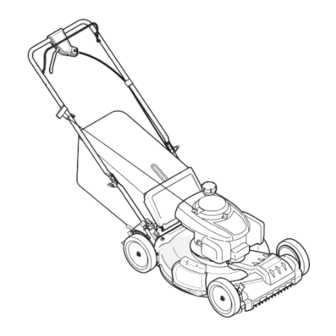
Self Propelled Mower — Model Series VA20 & VB20
IMPORTANT:
READ SAFETY RULES AND INSTRUCTIONS
CAREFULLY BEFORE OPERATING EQUIPMENT.
769-06853
MTD Products Ltd., P. O. Box 1386, KITCHENER, ONTARIO N2G 4J1
PRINTED IN U.S.A.
1.10.11
Advertisement
Table of Contents

Related Manuals for White Outdoor VA20 Series


Summary of Contents for White Outdoor VA20 Series
- Page 1 Safety • Set-Up • Operation • Adjustments • Maintenance • Troubleshooting • Parts Lists • Warranty OPERATOR’S MANUAL Self Propelled Mower — Model Series VA20 & VB20 IMPORTANT: READ SAFETY RULES AND INSTRUCTIONS CAREFULLY BEFORE OPERATING EQUIPMENT. 769-06853 MTD Products Ltd., P. O. Box 1386, KITCHENER, ONTARIO N2G 4J1 PRINTED IN U.S.A.
-
Page 2: Table Of Contents
Choose from the options below: ◊ Visit our web at www.whiteoutdoor.ca ◊ Locate your nearest dealer from Customer Support: 1-800-668-1238 ◊ Contact White Outdoor • P.O. Box 1386 • 97 Kent Avenue • Kitchener, Ontario, Canada • N2G 4J1... -
Page 3: Safe Operation Practices
Important Safe Operation Practices WARNING: This symbol points out important safety instructions which, if not followed, could endanger the personal safety and/or property of yourself and others. Read and follow all instructions in this manual before attempting to operate this machine. Failure to comply with these instructions may result in personal injury. - Page 4 A missing or damaged discharge cover can cause blade When starting engine, pull cord slowly until resistance contact or thrown object injuries. is felt, then pull rapidly. Rapid retraction of starter cord (kickback) will pull hand and arm toward engine faster than Many injuries occur as a result of the mower being pulled you can let go.
- Page 5 Service Check the blade and engine mounting bolts at frequent intervals for proper tightness. Also, visually inspect blade for damage (e.g., bent, cracked, worn) Replace blade with Safe Handling Of Gasoline: the original equipment manufacture’s (O.E.M.) blade only, To avoid personal injury or property damage use extreme listed in this manual.
- Page 6 Notice Regarding Emissions Spark Arrestor Engines which are certified to comply with California and federal WARNING: This machine is equipped with an EPA emission regulations for SORE (Small Off Road Equipment) internal combustion engine and should not be used are certified to operate on regular unleaded gasoline, and on or near any unimproved forest-covered, brush may include the following emission control systems: Engine covered or grass-covered land unless the engine’s...
- Page 7 Safety Symbols This page depicts and describes safety symbols that may appear on this product. Read, understand, and follow all instructions on the machine before attempting to assemble and operate. Symbol Description READ THE OPERATOR’S MANUAL(S) Read, understand, and follow all instructions in the manual(s) before attempting to assemble and operate DANGER —...
-
Page 9: Assembly & Set-Up
Assembly & Set-Up Contents of Carton • One Lawn Mower • One Grass Catcher† • One Bottle of Oil • One Lawn Mower Operator’s Manual • One Engine Operator’s Manual • One Side Discharge Chute† † If Equipped NOTE: Please be aware that this Operator’s Manual covers both Follow the steps below to complete handle assembly: the low and high wheel models of this mower. - Page 10 Figure 3-6 Figure 3-4 NOTE: When pulling upward on handle, make sure to not Grass Catcher (If Equipped) pull handle all the way out. Follow steps below to assemble the grass catcher (if Insert the T-bolts removed earlier through the needed).
- Page 11 Adjustments Cutting Height There is a cutting height adjustment lever located above the front and rear right wheel. Pull the height adjustment lever towards wheel. Move lever to desired position for a change in cutting height. See Fig. 3-10 or Fig. 3-11. NOTE: For mowers with low wheels, the height adjustment levers move in the opposite direction to adjust;...
- Page 12 Handle Pitch (If Equipped) Drive Control For convenience of operation, you may be able to adjust the The adjustment wheel is located in the drive control handle pitch of the handle as follows: housing and is used to tighten or loosen the drive belt. You will need to adjust the drive control if the mower does not propel Remove wing nuts and carriage bolts from handle.
-
Page 13: Controls & Features
Controls and Features Blade control Drive control Recoil Starter Side Discharge Deck Wash chute cutting Height Adjustment Lever cutting Height Adjustment Lever Mulch Plug Figure 4-1 Blade Control Grass Catcher (If Equipped) The blade control is attached to the upper handle of the mower. The grass catcher, located at the rear of the mower, is used to bag Depress and squeeze it against the upper handle to operate the the grass clippings for disposal at another site. -
Page 14: Operation
Operation Before Starting Engine Service the engine with gasoline and oil as instructed in the separate engine manual. Starting Engine WARNING: Be sure no one other than the operator is standing near the lawn mower while starting engine or operating mower. Never run engine indoors or in enclosed, poorly ventilated areas. - Page 15 Using Your Lawn Mower Using Grass Catcher Be sure lawn is clear of stones, sticks, wire, or other objects You can use the grass catcher to collect clippings while you are which could damage lawn mower or engine. Such objects could operating the mower.
-
Page 16: Maintenance & Adjustment
Maintenance & Adjustments Maintenance If your mower is equipped with ball bearing wheels, lubricate at least once a season with a light oil, all other types require no lubrication. However, if the wheels are General Recommendations removed for any reason, lubricate the surface of the Always observe safety rules when performing any axle bolt and the inner surface of the wheel with light maintenance. - Page 17 Engine Deck Wash (If Equipped) Refer to the separate engine manual for engine Your mower’s deck may be equipped with a water port on its maintenance instructions. surface as part of its deck wash system. Maintain engine oil as instructed in the separate engine Use the deck wash to rinse grass clippings from the deck’s manual packed with your unit.
-
Page 18: Service
Service Blade Care Lubricate the engine crankshaft and the inner surface of the blade adapter with light oil. Slide the blade adapter WARNING: onto the engine crankshaft. Place the blade on the adapter When removing the cutting blade for sharpening or replacement, protect your hands with such that the side of the blade marked “Bottom”... -
Page 19: Troubleshooting
Troubleshooting Problem Cause Remedy Engine Fails to start Blade control disengaged. Engage blade control. Spark plug boot disconnected. Connect wire to spark boot. Fuel tank empty or stale fuel. Fill tank with clean, fresh gasoline. Engine not primed (if equipped with primer). Prime engine as instructed in the Operation section. -
Page 20: Replacement Parts
Replacement Parts Component Part Number and Description 734-2042A Wheel (Front - 8” x 2.125”, SL:Z) 734-04568 Wheel (Rear - 8” x 2.125”, SL:Z) 634-04630 Wheel (Rear - 11” x 2”, SL:Z) 731-07486 Discharge Chute (WOP) † 731-07131 Discharge Chute (Columbia) †... -
Page 21: Warranty
THREE YEAR LIMITED WARRANTY The limited warranty set forth below is given by MTD Products Limited with respect to new merchandise purchased and used in Canada and/or its territories and possessions (either entity respectively, “MTD”). MTD warrants this product (excluding its normal wear parts as described below) against defects in material and workmanship for a period of three (3) years commencing on the date of original purchase and will, at its option, repair or replace, free of charge, any part found to be defective in materials or workmanship. - Page 22 Notes...
Need help?
Do you have a question about the VA20 Series and is the answer not in the manual?
Questions and answers