
Related Manuals for Megger DET2/3-ETK-50M


Summary of Contents for Megger DET2/3-ETK-50M
- Page 1 DET2/3 Advanced Earth (Ground) Tester User Guide 1.800.544.2843 www.calcert.com sales@calcert.com...
-
Page 2: Table Of Contents
Contents Safety Safety warnings ...............................1 Live earth safety precautions ..........................2 Voltage measurement categories ........................2 CAT IV ................................2 CAT III ................................2 CAT II ................................2 Test leads and clamps ............................2 Safety and hazard icons ..........................3 Warning Icons ..............................3 Warnings, Cautions and Notes .........................3 Warnings ...............................3 Cautions ................................3 Notes ................................3... - Page 3 Set-up Modify parameters............................12 General set-up ...............................12 Graph set-up ..............................13 Language set-up ............................13 Earth / ground resistance Test procedure .............................14 Earth / ground resistivity Test procedure .............................17 Continuity Test Test procedure .............................20 Null test leads ..............................21 Leakage Current Test Test procedure .............................22 See Data management (page 33).
- Page 4 Maintenance General maintenance .............................36 Cleaning ................................36 Battery ................................36 Battery status ...............................36 Battery replacement.............................37 Battery charge .............................38 12 V supply ..............................38 Specifications Measurement specifications ...........................39 Instrument specifications..........................40 Instrument calibration check tool ........................40 Electrical specification ..........................40 Mechanical specification ..........................40 Clamp calibration check tool ..........................41 Electrical specification ..........................41 Mechanical specification ..........................41 Accessories...
-
Page 5: Safety
ƒ If a battery is suspected to be faulty, replace it with a Megger approved battery pack. Refer to the User Guide for instructions on how to change the battery. -
Page 6: Live Earth Safety Precautions
Test leads and clamps Megger supply test leads designed for the DET2/3 which are rated correctly for the test voltage generated by this instrument, but not all are rated for mains connection. Users must select the correct leads for their project, this will be either low voltage type rated 50 V, 1 A or leads designed for mains environment rated at 300 V. -
Page 7: Safety And Hazard Icons
Note: The warning will not operate if the instrument is set to Off. Internal Error Warning Internal Error Warning switch off and back on. Contact Megger if not Read the User Guide Refer to the user guide if this message shows. -
Page 8: Introduction
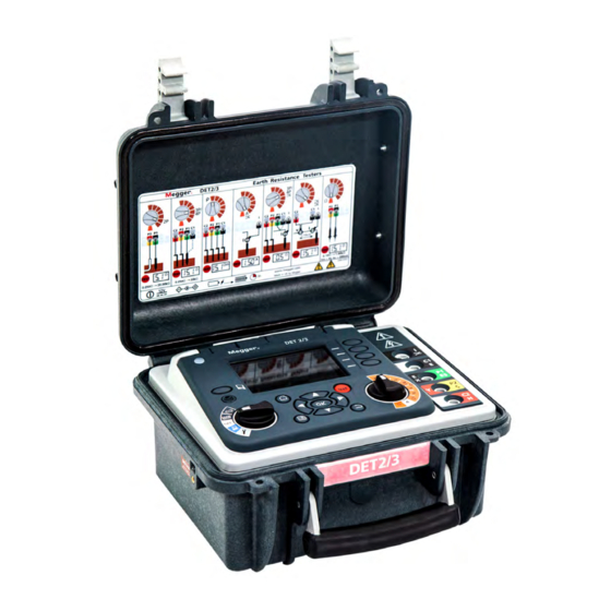
Introduction Introduction This user guide details the operational and functional details of the DET2/3 advanced earth (ground) tester. Please read this user guide fully before attempting to use the DET2/3. The DET2/3 automatic earth test instrument is designed to measure earth Electrode Resistance and Soil Resistivity, with highly accurate results. -
Page 9: Overview
Overview Overview User interface Description Description External power / battery charge socket Function switch (Controls (page 7)) Display Navigation control panel (page 8) USB: 1x Type A / 1x Type B Mode switch (Controls (page 7)) Soft keys (page 9) Save (Test Result Management (page 36)) Terminals (page 8) External power LED (Power on / Charge (page 10)) -
Page 10: Display
Overview Display Description Description Test mode: Secondary measurement result Status bar Data management mode: Asset number Test mode: Test parameters Main display / Primary measurement result 5 Data management mode: Record name Soft key functions 1.800.544.2843 www.calcert.com sales@calcert.com... -
Page 11: Controls
Overview Controls Refer to user interface (page 5). Mode switch Function switch Ω Ω Description Description ρ (Resistivity) Continuous graphical mode (page 11) Manual mode (page 11) 4 Pole (ART) Power on / off (page 10) 4 Pole Test result management (page 33) 3 Pole (ART) Set-up (page 12) 3 Pole... -
Page 12: Navigation Control Panel
Overview Navigation control panel TEST Description Description Home Back Navigation arrows Test Menu Terminals See Test methods and set-up (page 23) CAT IV 300V Description MCC1010 (used for ART, Noise current and stakeless tests) MVC1010 / C1 E Voltage clamp, (current) E/X / P1 ES (Potential) Y / P2 S (Potential) MVC1010 / C2 H Voltage clamp (current) -
Page 13: Soft Keys
Overview Soft keys Soft Key Description Soft Key Description Select 15 / 50 V Delete all test records 15/50V Noise filter on / off Send all test records to USB Automatic frequency Scan Delete single test record Earth / ground resistivity test Send single test record to USB 2 aR method... -
Page 14: Operation
Operation Operation Before each use of the instrument, visually inspect the instrument case, test leads, stakes and connectors to confirm their condition is good, with no damaged or broken insulation. Power on / off „ Rotate the mode switch away from Off to a mode to power up and activate the instrument „... -
Page 15: Test Leads And Terminal Connections
Operation Test leads and terminal connections Test lead set-up and terminal connections are described as part of the test procedure. Important: When the instrument is connected to electrodes, make sure that all leads and cables are fully unwound and laid out without loops. Important: When running test leads out to each remote spike, take care not to lay them close to each other. -
Page 16: Set-Up
Set-up Set-up This section details the instrument set-up. Modify parameters 1. Set the Mode switch to 2. Press to select a set-up group. 3. See instructions below for each set-up group. Note: The set-up group screen is not active until is pressed. -
Page 17: Graph Set-Up
Set-up Graph set-up „ Graph length: 1, 5, 10, 15 min „ Moving Average: 5, 10, 25, 50, 100 1. Press to scroll through the parameters. 2. Press to select the highlighted parameter. 3. Use to move through the options. 4. -
Page 18: Earth / Ground Resistance
Earth / ground resistance Earth / ground resistance Test procedure Warning: Make sure the circuit is de-energised, before the instrument is connected for measurement. Note: Manual or Continuous Graphical Mode (see Test modes (page 11). Step Manual Mode Continuous Graphical Mode 15 m to 25 m 15 m to 25 m 15 m to 25 m... - Page 19 Earth / ground resistance Manual mode Continuous graphical mode 61.8% of EC 38.2% of EC 61.8% of EC 38.2% of EC Connect test leads to instrument Connect test leads to instrument Electrode under test Potential spike Current spike Electrode under test Potential spike Current spike Set test parameters...
- Page 20 Earth / ground resistance Manual mode Continuous graphical mode Press / Repeat test Press / Repeat test See Data management (page 33). Repeat test if required. While the test result is shown, test parameters can be modified for the next test. If required test parameters can be repeated.
-
Page 21: Earth / Ground Resistivity
Earth / ground resistivity Earth / ground resistivity Test procedure MVC1010 MVC1010 MCC1010 Setup test C1 (E) P1 (ES) P2 (S) C2 (H) MVC1010 MVC1010 MCC1010 Wenner Connect pins / stakes C1 (E) P1 (ES) P2 (S) C2 (H) Schlumberger Note: Set up the test leads and stakes as required by the selected test method (on screen). - Page 22 Earth / ground resistivity Resistivity The DET2/3 can measure and calculate resistivity using the Wenner or Schlumberger methods. These are very similar, both involving placing four pins / stakes into the earth / ground. These only penetrate the soil by a short distance.
- Page 23 Earth / ground resistivity Start test Manual mode Continuous graphical mode Press and hold TEST Press Press until padlock icon TEST TEST appears Note: : Stop the current data stream and restart the graph. : Activate / deactivate the average display : Go back to test settings (the Ready screen) ...
-
Page 24: Continuity Test
Continuity Test Continuity Test Warning: Make sure the circuit is de-energised, before the instrument is connected for measurement. Note: To remove any test lead resistance in the test result, Null the test leads (see Null test leads (page 21)). Test procedure Ω... -
Page 25: Null Test Leads
Continuity Test Manual mode Continuous graphical mode Press Press See Data management (page 33). Note: Press Save at any time to save the current reading. Null test leads Note: Test must be running to be able to Null the test leads. The Null function only works when the measured resistance is less than 10 Ω. -
Page 26: Leakage Current Test
Leakage Current Test Leakage Current Test Test procedure Connect MCC1010 Set function to A Ω Ω Set the mode Place MCC1010 around MVC1010 MVC1010 MCC1010 conductor to be tested Start Test Continuous graphical mode Manual mode Press Press to start TEST TEST End Test... -
Page 27: Test Methods And Set-Up
Test methods and set-up Test methods and set-up The test methods detailed in this section is not exhaustive, see the booklet 'Getting Down To Earth' for more information on other tests and methods. Key to images in this section: „ P: Potential spike „... -
Page 28: Four Terminal Art Test Lead Set-Up
Test methods and set-up Four terminal ART test lead set-up MVC1010 MVC1010 MCC1010 C1 (E) P2 (S) C2 (H) P1 (ES) 100% Three terminal test lead set-up 15 m to 25 m 15 m to 25 m Important: The current stake / pin, potential spike and earth / ground electrode must be placed in a straight line. Important: When running test leads out to each remote stake / pin, take care not to lay them close to each other. -
Page 29: Three Terminal Art Test Lead Set-Up
Test methods and set-up Three terminal ART test lead set-up MVC1010 MVC1010 MCC1010 P1 (ES) P2 (S) C2 (H) 100% Slope method (FoP) Description Extract from the technical guide Getting Down to Earth: It has been shown that the true earth resistance of an electrode system is obtained when the temporary potential P is positioned at a distance from the electrical centre of the system equal to 61.8% of the distance from the electrical centre to the temporary current probe. - Page 30 Test methods and set-up 7. Since D (distance to the current probe) is already known, calculate a new D (distance of the potential probe) then insert the potential probe at this new distance from E. Now measure the earth resistance by placing the potential probe at this new distance D .
- Page 31 Test methods and set-up Table 1: Values of D for various values of µ µ µ µ 0.40 0.643 0.80 0.580 1.20 0.494 0.41 0.642 0.81 0.579 1.21 0.491 0.42 0.640 0.82 0.577 1.22 0.488 0.43 0.639 0.83 0.575 1.23 0.486 0.44 0.637...
-
Page 32: Slope Four Terminal Test Lead Set-Up
Test methods and set-up Slope four terminal test lead set-up > 50 m Slope three terminal test lead set-up > 50 m Electrode under test Potential spike Current spike 1.800.544.2843 www.calcert.com sales@calcert.com... -
Page 33: Rule (Fop)
Test methods and set-up 61.8% Rule (FoP) 61.8% Four terminal test lead set-up 61.8% of EC 38.2% of EC 61.8% Three terminal test lead set-up Electrode under test Potential spike Current spike 100% 1.800.544.2843 www.calcert.com sales@calcert.com... -
Page 34: Two Terminal Earth Resistance Test
Test methods and set-up Two terminal earth resistance test Warning: Make sure the circuit is de-energised, before the instrument is connected for measurement. This will measure the resistance between the P1(X) and P2(Y) terminals using an ac test voltage. This method may not be suitable for continuity and bonding tests (refer to local regulations). -
Page 35: Calibration Check Tools
Calibration check tools Calibration check tools The instrument's calibration should be checked, before and after each test, against the calibration check tool. Instrument calibration check 1. Make sure that the mode switch is set to Off. 2. Connect the instrument as shown: MVC1010 MVC1010 MCC1010... -
Page 36: Clamp Calibration Check
Calibration check tools Clamp calibration check 1. Make sure that the mode switch is set to Off. 2. Connect the instrument as shown: MVC1010 MVC1010 MCC1010 Dual Clamp calibration check Hold clamps against these faces 3. Close the MCC1010 around one loop of the clamp calibration check tool. 4. -
Page 37: Data Management
Data management Data management Use test result management mode of view saved test results and transfer saved test results to USB drive or PC. Test result data is saved in two formats: „ As a Data File: Data saved from manual or guided mode saved as a single data file. „... -
Page 38: Usb Connection
Data management to move to Asset ID. 6. Press (Red bar visible) 7. Press ƒ Data file: Test001.tab. ƒ Graph file: Graph001.tab. 8. Enter a test result three digit number. Keyboard show - use arrow keys to navigate. 9. Press to save and return. -
Page 39: Single Test Result: Download Or Delete
Data management Single test result: download or delete Connect a USB memory device to the instrument. 1. Set the mode switch to 2. Select 3. Press 4. Press to select record number (Red bar visible) 5. Press to select a test result: Download a single test record Delete a single test record „... -
Page 40: Maintenance
Caution: Old batteries must be disposed of in accordance with local regulations. Caution: Always set the instrument to Off and remove test leads before battery is removed and installed. Only use approved batteries supplied by Megger. Approved batteries (see Specifications (page 39)). -
Page 41: Battery Replacement
Warning: Disconnect all leads before removing case. Caution: Protect the face and switches of the instrument when turning it upside-down. Note: Replace with Megger approved battery, part number 1002-552 only. 1. Remove lid by opening to approximately 70° and sliding right. -
Page 42: Battery Charge
The instrument will function normally with the power supply in use. Use only the power supply provided by Megger; other supplies may introduce noise into the measurement, affecting accuracy and instrument stability. -
Page 43: Specifications
Specifications Specifications Only values with tolerance or limits are guaranteed data. Parameters without tolerances are for information only. Measurement specifications 2, 3 and 4 terminal resistance Range 0.001 Ω to 20.00 kΩ Auto range Accuracy at 23 °C ±0.5% of reading ±2 digits ±10 mΩ... -
Page 44: Instrument Specifications
Specifications Instrument specifications Display Backlit, colour, WQVGA display 5.25 in Operating temperature From -10 to 40 °C (14 to 104 °F) Operating humidity 90% RH max at 40 °C Storage temperature From -20 to 60 °C (4 to 140 °F) Temperature coefficient <... -
Page 45: Clamp Calibration Check Tool
Specifications Clamp calibration check tool Electrical specification Resistance 25 Ω ±0.1% Mechanical specification Operating temperature -10 °C to 50 °C (14 °F to 122 °F) 0% to 85% RH at +35 °C (95 °F) Storage temperature -20 °C to 70 °C (-4 °F to 158 °F) Dimensions 111 x 216 x 45 mm (4.4 x 8.5 x 1.8 in) Weight... -
Page 46: Accessories
Accessories Accessories Warning: Use only Megger approved test leads and accessories with this instrument. Item Part Number Cable reel kit ETK30 1010-176 Cable reel kit ETK50 1010-177 Cable reel kit ETK100 1010-178 Cable reel kit ETK50C 1010-179 Cable reel kit ETK100C... -
Page 47: Repair And Warranty
Repair and warranty Repair and warranty If an instrument’s protection has been impaired it should not be used, but sent for repair by suitably trained and qualified personnel. The protection is likely to be impaired if for example, it shows visible damage, fails to perform the intended measurements, has been subjected to prolonged storage under unfavourable conditions, or has been subjected to severe transport stresses. -
Page 48: Calibration And Repair
3. Pack the instrument carefully to prevent damage in transit. 4. Before the instrument is sent to Megger, freight paid, make sure that the returns label is attached, or that the RA number is clearly marked on the outside of the package and on any correspondence. -
Page 49: Approved Service Centres
End of life WEEE directive The crossed out wheeled bin symbol placed on Megger products is a reminder not to dispose of the product at the end of its life with general waste. Megger is registered in the UK as a Producer of Electrical and Electronic Equipment (registration No.: WEE/ HE0146QT). -
Page 50: Weee Directive
Hereby, Megger Instruments Limited declares that radio equipment manufactured by Megger Instruments Limited described in this user guide is in compliance with Directive 2014/53/EU. Other equipment manufactured by Megger Instruments Limited described in this user guide is in compliance with Directives 2014/30/EU and 2014/35/EU where they apply.
Need help?
Do you have a question about the DET2/3-ETK-50M and is the answer not in the manual?
Questions and answers