Advertisement
Quick Links
Advertisement

Subscribe to Our Youtube Channel
Related Manuals for MSTRONIC SOL10P12 Series


Summary of Contents for MSTRONIC SOL10P12 Series
- Page 1 SOL10P12 Series Solar & PoE Battery Charger USER’S MANUAL Mstronic Co., Ltd.
- Page 2 User’s Manual SOL10P12 Series Features: Dual Input, from solar panel and/or PoE (Solar First) to charge 12V battery, and another two outputs: PoE output on front and/or terminal block on rear Built-in DC/DC converter, with various passive PoE output, 24V, 48V, 56V available.
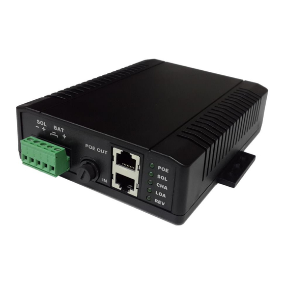
- Page 3 User’s Manual SOL10P12 Series Panel Description Item Name Descriptions PoE power input indicator: the LED lights when the PoE input jack (the POE : lower jack) has 36V~57V input. Solar power input indicator: the LED lights when SOL terminal is SOL : connecting to a solar panel and the solar panel input voltage is over 12V.
- Page 4 User’s Manual SOL10P12 Series Operation Guide 1. Connect the battery to the BAT terminal. Make sure the polarities are correctly connected. Sequentially connect the solar panel to SOL terminal and connect POE source to PoE input (lower) jack. (If solar panel or PoE source is installed before the battery, and if the polarities of the battery be reversed, then the fuse will be burnt.)
- Page 5 User’s Manual SOL10P12 Series 8. It can be two separate outputs on the rear panel, make sure the total draw is not over the limit. 9. The V- of PoE input, Solar input, and battery(-) are not the same grounding, must be properly isolated.
- Page 6 User’s Manual SOL10P12 Series Electrical specifications 1. INPUT Two Input Source: A. Solar Panel : 18V~45V, B. POE : 36 V~57V (only use 4 pairs injector for more than 35W input.) OUTPUT Output 1 Output 2 Model No. (at rear terminal) (at front/upper RJ45) 24V/1.25A...
- Page 7 User’s Manual SOL10P12 Series 3. Battery Charge Current: A. Solar Panel: depends on the solar panel, 10A max, B. POE: fixed current, 2.0A max 4. Battery Types: 12V AGM Battery Protection: Battery Polarity Reverse Protection: If only battery connected to terminal, when the battery polarities...
-
Page 8: General Description
User’s Manual SOL10P12 Series Output Short Circuit Protection: When the rear output terminal or PoE output be short circuit, protection be active, the product stop output and auto-recover when the terminal back to normal connection. Battery Output Current Limit: The fuse will be burnt when battery output current over 10A Load Output Voltage Limit: The output voltage of the rear terminal is the same as battery. - Page 9 User’s Manual SOL10P12 Series 7. Pin out: @1000M RJ-45 Input (Data & Power) RJ-45 Output (Data & Power) Compliant to 802.3af/at Depends on individual models Symbol Description Symbol Description (+/-)Vdc + BI_DA+ power(+/-)+Data Pair A+ (+/-)Vdc + BI_DA+ power(+/-)+Data Pair A+...
Need help?
Do you have a question about the SOL10P12 Series and is the answer not in the manual?
Questions and answers