Sharp XE-A301 Service Manual
Hide thumbs
Also See for XE-A301:
- Instruction manual (384 pages) ,
- Bedienungsanleitung (80 pages) ,
- Quick start manual (6 pages)
Advertisement
Quick Links
q
CHAPTER 1. SPECIFICATIONS . . . . . . . . . . . . . . . . . . . . . . . . . . . . 1
CHAPTER 2. OPTIONS . . . . . . . . . . . . . . . . . . . . . . . . . . . . . . . . . . . 4
CHAPTER 3. MASTER RESET AND PROGRAM RESET. . . . . . . . . 4
CHAPTER 4. HARDWARE DESCRIPTION . . . . . . . . . . . . . . . . . . . . 5
CHAPTER 5. DIAGNOSTIC PROGRAM . . . . . . . . . . . . . . . . . . . . . 10
CHAPTER 6. IPL FROM EP-ROM . . . . . . . . . . . . . . . . . . . . . . . . . . 14
CHAPTER 7. CIRCUIT DIAGRAM AND PWB LAYOUT . . . . . . . . . 15
Parts marked with "!" are important for maintaining the safety of the set. Be sure to replace these parts with specified
ones for maintaining the safety and performance of the set.
SERVICE MANUAL
CONTENTS
SHARP CORPORATION
CODE : 00Z
ELECTRONIC
CASH REGISTER
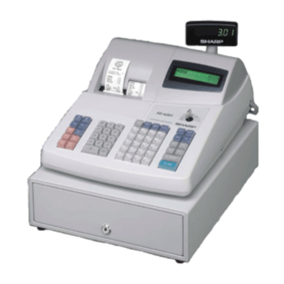
XE-A301
MODEL
SRV KEY : Not necessary
PRINTER : PR-45MII II II II
(V version)
This document has been published to be used
for after sales service only.
The contents are subject to change without notice.
XEA301VSME
Advertisement

Related Manuals for Sharp XE-A301


Summary of Contents for Sharp XE-A301
-
Page 1: Table Of Contents
SERVICE MANUAL CODE : 00Z XEA301VSME ELECTRONIC CASH REGISTER XE-A301 MODEL SRV KEY : Not necessary PRINTER : PR-45MII II II II (V version) CONTENTS CHAPTER 1. SPECIFICATIONS ......1 CHAPTER 2. -
Page 2: Chapter 1. Specifications
Clear key 00, 0~9 Numeric keys 2. RATING PLU/SUB PLU/Subdepartment key DEPT # Department code entry key XE-A301 DEPT SHIFT Department shift key Weight 12.7kg CLK# Clerk code entry key Dimensions 421 (W) x 429 (D) x 297 (H) mm... - Page 3 ■ ■ ■ ■ Operator display The mode switch has these settings: This mode locks all register operations. (AC power turns off.) Function message display area No change occurs to register data. OP X/Z: To take individual clerk X or Z reports, and to take flash Clerk code or mode name reports.
- Page 4 6. PRINTER 7. DRAWER 6-1. PRINTER [OUTLINE] • Part number: PR-45M II • Standard equipment: Yes • NO. of station: 2 (Receipt and journal) • Max. number of additional drawers: 0 • Validation: • The drawer consists of: 1) Drawer box (outer case) and drawer •...
-
Page 5: Chapter 2. Options
CHAPTER 2. OPTIONS 1. OPTIONS (NO) 2. SERVICE OPTIONS (NO) 3. SUPPLIES PRICE NAME PARTS CODE DESCRIPTION RANK TPAPR6645RC05 Thermal roll paper 5 ROLLS/PACK 4. SPECIAL SERVICE TOOLS PRICE NAME PARTS CODE DESCRIPTION RANK UKOG-6705RCZZ RS-232 Loop-back connector CHAPTER 3. MASTER RESET AND PROGRAM RESET 1. -
Page 6: Chapter 4. Hardware Description
CHAPTER 4. HARDWARE DESCRIPTION 1. BLOCK DIAGRAM 2. MEMORY MAP XE-A301 2-1. ADDRESS MAP BANK 0 BANK 1 BANK 2 BANK 3 POWER DRAWER /CS0 SUPPLY 00000h 00400h RAM 10KB Internal RAM area 256KB 02C00h 10KB Internal rserved area 04000h... - Page 7 3. PRINTER CONTROL 3-1. STEPPING MOTOR CONTROL 3-2. HEAD CONTROL The stepping motor is driven at a constant voltage by Sanken HEAD:832 dots in all. Printable range: 384 dots at receipt side; 384 dots STA471A. at journal side 1step: 0.125mm, 1dot: 1step Related PORT Printing speed 50mm/s CPU PORT...
- Page 8 4. I/O M16C/24 PORT MEMORY SPACE: NORMAL MODE PROCESSOR MODE: MICRO PROCESSOR MODE It is used by (SEPARATE BUS 8bit Width) Signal Initial Signal Initial PORT Function PORT Function MODE name name value name name value MODE Out L /HLDA (NU) Out L Out L...
- Page 9 Power supply/CONTROL pins PORT Pin name Function PORT Pin name Function BYTE BYTE Connected to VCC Connected to VCC CNVss CNVss Connected to GND connected to GND /RESET /RESET AVss AVss Connected to GND Xout Xout OPEN Vref Vref Connected to VCC Connected to GND AVcc AVcc...
- Page 10 5-3. KEYSCAN MATRIX MODE Time X1/Z1 X2/Z2 Others PF-R PF-J HEAD DRAWER RS/CI OPEN 5-4. DISPLAY 7. REWRITING FLASH MEMORY This machine has an LCD display, 5 x 7 dots, 2 lines, at the front side IPL from EP-ROM: After IPL SW is set to ONA the program is started and a 7-digit LED at the pop-up side.
-
Page 11: Chapter 5. Diagnostic Program
CHAPTER 5. DIAGNOSTIC PROGRAM 1. TEST ITEMS 2. DESCRIPTION OF EACH DIAG PROGRAM The test items are as follows: 1) DISPLAY BUZZER TEST Code Description 1 Key operation Display buzzer test 100 3 RCPT/PO Key code Printer test 2 Test procedure Keyboard test OP display D I S P... - Page 12 3) PRINTER TEST 5) MODE SWITCH TEST 1 Key operation 1 Key operation 102 3 105 3 RCPT/PO RCPT/PO 2 Test procedure 2 Test procedure OP display R / J P G M P R I N T E R OP display M O D E P G M...
- Page 13 4 End of testing 41000H , 42000H , 44000H , 48000H , 50000H When any key is pressed, the date and time are printed and the test OP display mode will be terminated. P G M R A M 1 2 0 X X X X X X X X X X X X 3 Check:...
- Page 14 ******** (Version) When the test ends E – – ~ – – abnormally: 3. KEY CODE TABLE ******** (Model name) XE-A301 ******** (Version) 083 067 147 148 003 004 12) AD CONVERSION PORT TEST 052 132 084 068 002 005...
-
Page 15: Chapter 6. Ipl From Ep-Rom
CHAPTER 6. IPL FROM EP-ROM Before working on the installation, unplug the AC cord from the AC out- 6. Unplug the AC cord from the AC outlet. let. 7. Remove the IPL ROM to the IC socket of the MAIN PWB. 1. - Page 16 /FRDY /BUSY XE-A301V CIRCUIT DIAGRAM AND PWB LAYOUT – 15 –...
- Page 17 XE-A301V CIRCUIT DIAGRAM AND PWB LAYOUT – 16 –...
- Page 18 XE-A301V CIRCUIT DIAGRAM AND PWB LAYOUT – 17 –...
- Page 19 XE-A301V CIRCUIT DIAGRAM AND PWB LAYOUT – 18 –...
- Page 20 XE-A301V CIRCUIT DIAGRAM AND PWB LAYOUT – 19 –...
- Page 21 XE-A301V CIRCUIT DIAGRAM AND PWB LAYOUT – 20 –...
- Page 22 XE-A301V CIRCUIT DIAGRAM AND PWB LAYOUT – 21 –...
- Page 23 COPYRIGHT 2003 BY SHARP CORPORATION All rights reserved. Printed in Japan. No part of this publication may be reproduced, stored in a retrieval system, or transmitted. In any form or by any means, electronic, mechanical, photocopying, recording, or otherwise, without prior written permission of the publisher.
Need help?
Do you have a question about the XE-A301 and is the answer not in the manual?
Questions and answers