Elkron MP500/8 Installation Manual
Remote controllable alarm control panels
Hide thumbs
Also See for MP500/8:
- Programming manual (140 pages) ,
- User manual (96 pages) ,
- User addendum (52 pages)

Related Manuals for Elkron MP500/8


Summary of Contents for Elkron MP500/8
- Page 1 MP500/4N - MP500/8 MP500/16 Remote controllable alarm control panels On the website www.elkron.com, you may find updated information relating to the documentation provided with the product. DS80MP5L-011H LBT80896...
- Page 2 This manual may also contain references to or information about products (hardware or software) or services that are not yet on the market. These references or information in no way mean that the company intends to market such product or services. Elkron is a brand name of URMET S.p.A. All the brands cited in the document belong to their respective owners.
-
Page 3: Table Of Contents
Preface ........................................9 Conformity with EN50131-1 ................................... 9 IMQ ........................................10 How the manual is organised ................................10 Conventions used ....................................11 Glossary ....................................... 12 The MP500/4N-MP500/8-MP500/16 systems ..........................13 Main characteristics ................................13 System Architecture ................................14 1.2.1 Architecture 1.2.2 Bus Data 1.2.3... - Page 4 2.3.2.9 Combined passive IR and microwave detector ......................31 2.3.2.10 External detectors ............................... 31 2.3.3 The signalling devices 2.3.3.1 Siren ................................... 31 2.3.3.2 Flasher ..................................31 2.3.3.3 Communicator ................................31 2.3.4 The complementary devices 2.3.4.1 Keypad ..................................32 2.3.4.2 Reader ..................................32 2.3.4.3 Remote control ................................
- Page 5 5.3.3 Fastening to the wall 5.3.4 Battery compartment and fastening points for the optional features in the MP500/4N - MP500/8 control panels 5.3.5 Assembling expansion modules in the MP500/4N - MP500/8 control panels Preparing the MP500/16 control panel ..........................56 5.4.1...
- Page 6 7.12 TROUBLESHOOTING ............................... 105 TECHNICAL SPECIFICATIONS ..............................108 MP500/4N CONTROL PANEL ............................108 MP500/8 CONTROL PANEL .............................. 109 MP500/16 CONTROL PANEL ............................110 KEYPAD DISPLAY KP500D/N - KP500DV/N ........................111 KEYPAD TOUCH SCREEN KP500DP/N .......................... 111 KEYPAD TOUCH SCREEN KP500D/ST ........................... 112 DK500M-E ELECTRONIC KEY READER .........................
- Page 7 Figure 19 - Protection of the MP500/4N - MP500/8 from tampering and removal ................... 53 Figure 20 - Fastening points for optional features in the MP500/4N - MP500/8 control panels ............... 54 Figure 21 - Fastening points for optional features in the MP500/4N - MP500/8 control panels ............... 54 Figure 22 - Fastening points for optional features in the MP500/4N - MP500/8 control panels ...............
- Page 8 Figure 66 - Radio connection test menu ..............................100 TABLE INDEX Table 1 - Maximum system dimension MP500/4N, MP500/8 and MP500/16 ..................15 Table 2 - Max number of wired inputs and outputs ..........................15 Table 3 - Comparison of wired and radio technologies ........................... 28 Table 4 - Control panel battery autonomy ...............................
-
Page 9: Preface
The grade depends on how the system is constructed and/or configured. With an ATS4 communicator connected, the MP500/8 and MP500/16 control panels respect notification options A and B – Grade 3. With the telephone line connected, the MP500/4N, MP500/8, and MP500/16 control panels can respect the notification options A and B - Grade 2. -
Page 10: Imq
Chapter 1 describes the MP500/4N, MP500/8, and MP500/16 systems, their architecture and devices that may be part of the systems. Chapter 2 provides basic information about the alarm systems: how the alarm system is made, what it can do, the components it is made of and how they work. -
Page 11: Conventions Used
CONVENTIONS USED For clarity, the manual applies the following conventions: This symbol signals an important warning. This symbol signals a recommendation. This symbol indicates the compatibility with EN50131 grade 3 certification. The overall certification of the system is equal to the minimum certification of the devices installed and the functions enabled. -
Page 12: Glossary
GLOSSARY A logical function that requires that all the terms of the operation be true in order for the result to be true. Open An input is open when it receives a signal from a detector that is no longer in stand-by, for example, because of an attempted intrusion has been detected. -
Page 13: The Mp500/4N-Mp500/8-Mp500/16 Systems
ATTENTION! If the “emergency response call” is required, it is necessary to have a remote emergency response system in conformity with current legislation on this topic. To create a system that fully meets all the requirements of a fire detection system, consult Elkron's general catalogue in the Fire Prevention section. -
Page 14: System Architecture
Control panel, keypads, readers, expansion modules and radio modules are interconnected by a 4-wire bus. The 4 wires transmit information among the various devices and supply 12 V⎓ power from the MP500/4N, MP500/8 or MP500/16 control panel to the keypad, readers, expansion modules, and radio modules. -
Page 15: Maximum System Size
Electrical outputs Table 2 - Max number of wired inputs and outputs SYSTEM CONNECTIVITY The MP500/4N, MP500/8, and MP500/16 systems can be connected to the external environment in different ways, sending signals and receiving commands. Possible connection methods are: ... - Page 16 The table below illustrates the functions available according to the means of communications used. Means of communications used PSTN and Description of information PSTN and PSTN (IDP, ADF, transmitted or received Server: (SMS) (DTMF (modem) C200B, (vocal) tones) C200B P-P) ■...
-
Page 17: Connection With Remote User
DISCLAIMER The company declines any and all responsibility concerning the unavailability, temporary or permanent, of the PSTN or GSM telephone network that may affect the making of calls or the sending or programmed messages. Under conditions of a weak or disturbed field, there may be a decline in the performances of the GSM communication vector. Below are the various connections that can be managed by the MP500 systems and the functions that each one offers. -
Page 18: Connection With A Remote Pc
From the remote user towards the control panel The user, via calls to the control panel, can: Use remote management with vocal guide and commands in DTMF for: inquiring about the system status (armed/disarmed, alarms, and anomalies present); partition activation and deactivation; isolation and resetting of inputs;... -
Page 19: Connection With A Local Pc
From the control panel towards the remote user From the control panel, via outgoing calls, alarms and signals can be sent directly to the PC. From the remote user towards the control panel The user or installer, via calls to the control panel, or incoming calls to the control panel with return call, can: ... -
Page 20: Connection With An Alarm Reception Centre
1.3.4 Connection with an alarm reception centre Figure 5 - Diagram of connection with an alarm reception centre With the traditional telephone network interface (PSTN) ILT500-N, remote surveillance by an alarm reception centre may be used. The control panel sends alarms and signals to the centre using the IDP, ADF, or C200b protocols. The only certified protocol is IDP. For further information, please see 5.12.8 Connecting the telephone dialler. -
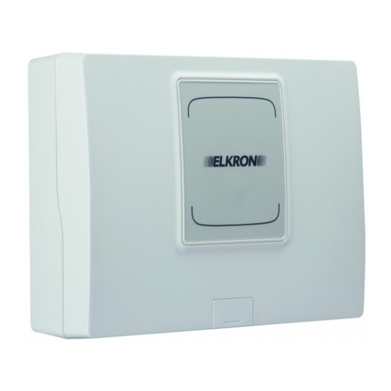
Page 21: Mp500/8 Control Panel
IT-USB/KEY interface and with Hi-Connect software installed (revision 3.50 or later). The programming can be saved on a USB pen drive. The functional capacities of the MP500/8 control panel can be increased with optional devices. EN50131 Certification: Grade 2 or Grade 3 - Class II 1.4.3... -
Page 22: Kp500D/N Command Keypad
ATTENTION! It can be used with MP500/4N, MP500/8 and MP500/16 systems. The SV500N is required to be able to use the vocal functions. The installation of the vocal synthesis board results in the loss of EN50131 certification. -
Page 23: Ep508 Expansion Module
1 balanced SAB input; 3 outputs (1 relay output and 2 electric outputs). The expansion is provided with no casing. It can be installed inside the MP500/4N, MP500/8 or MP500/16 control panels or inside a CP/EXP container. ATTENTION! the absence of a casing certified Grade 2 or 3 results in the loss of EN 50131 certification. -
Page 24: Dk50 Electronic Key
Each key has a distinct code, set by default, with more than 4 billion possible combinations. It is possible to program up to 16 keys for the MP500/4N control panel, up to 32 keys for the MP500/8 control panel and up to 64 keys for the MP500/16 control panel. Moreover, each key can be enabled or disabled individually and equipped with a descriptive name. -
Page 25: Mifare Dk70 Proximity Key
Each key has a distinct code, set by default, with more than 4 billion possible combinations. It is possible to program up to 16 keys for the MP500/4N control panel, up to 32 keys for the MP500/8 control panel and up to 64 keys for the MP500/16 control panel. Moreover, each key can be enabled or disabled individually and equipped with a descriptive name. -
Page 26: Img500/N Gsm Module
1.4.25 USB interface for connection to the PC and USB IT-USB/KEY keys Optional interface to connect a PC to the MP500/4N, MP500/8, and MP500/16 control panels for programming and a USB Pen Drive for saving and restoring system programming and other data. -
Page 27: Hi-Connect Application Software (Rev. 3.60 Or Later)
1.4.26 Hi-Connect application software (rev. 3.60 or later) Software for local programming with a PC and remote management of the MP500/4N, MP500/8, and MP500/16 control panels. Minimum PC configuration requirements: Intel Pentium IV 1. GHz processor or equivalent; 256 MB RAM;... -
Page 28: Basic Information
This chapter explains the composition of the intrusion alarm system and is intended for those who are designing an alarm system for the first time. If you have experience in designing installations, you can skip directly to Chapter 4, where the MP500/4N, MP500/8, and MP500/16 systems are discussed and their advanced and special functions are illustrated and explained with specific examples. -
Page 29: Radio Apparatus
Wired technology is particularly indicated: in new constructions or in those to be remodelled, where it is possible to have a conduit system where wires can be passed; in those situations where radio shields or significant sources of electromagnetic disturbances are found; Radio technology is particularly indicated: ... -
Page 30: The Devices Used To Create An Alarm System
THE DEVICES USED TO CREATE AN ALARM SYSTEM Essentially, an intrusion alarm system consists of four types of components: the control panel; the detectors; the signalling devices; the complementary devices. These components are generally separate, but sometimes a single device may enclose more than one. Below are illustrations of these components: what they are called, how they are made, and how they work. -
Page 31: Passive Infra-Red Detector (Ir)
2.3.2.6 Passive infra-red detector (IR) This detector is equipped with one or more IR sensors that measure the rapid variations of infra-red traces of the environment being controlled, indicating the presence of human beings, animals, or other "warm" objects that move. A variation of this type generates a signalling by the detector. -
Page 32: The Complementary Devices
2.3.4 The complementary devices The complementary devices complete the alarm system by adding functions and simplifying its use. The main complementary devices are: 2.3.4.1 Keypad The keypad is a device with multiple functions, including: authenticating the users on several levels; ... -
Page 33: Design: Configuration Of The Alarm System
3 - DESIGN: CONFIGURATION OF THE ALARM SYSTEM This chapter explains how to design and alarm system with the MP500/4N, MP500/8, and MP500/16 systems. Even if you have experience in designing intrusion alarm system, we advise you to read this chapter because it contains important information on how to get the most out of functions provided by the devices used and to comply with relative laws. -
Page 34: How To Design An Alarm System
Let's example the typical alarm system to understand how they are powered. Particular or complex systems can have different configurations. Wired systems The power supply and the batter are contained in the control panel, from which multipolar cables branch out to connect the various devices. -
Page 35: How To Protect Areas And People
3.3.3 How to protect areas and people The purpose of an intrusion alarm system is to prevent some prowler from accessing the areas to be protected without him noticing the system. This means monitoring openings and passages, which lead to two different techniques: ... -
Page 36: The Subdivision Into Partitions
3.3.4 The subdivision into partitions There are cases in which it is not necessary to install the alarm system everywhere or, examining the problem from another point of view, there may be occasions in which it may be preferable to be able to move freely in certain areas while leaving other protected. In other words, being able to partition the existing system, without having to plan two independent ones. -
Page 37: Choosing Devices
3.3.5 Choosing devices Choosing the devices to be used in the alarm system means having a clear idea of what they do and how they do it. If there should be any doubts, it could be useful to read paragraph The devices used to create an alarm system. 3.3.5.1 The detectors ... -
Page 38: Positioning The System Devices
3.3.6 Positioning the system devices Unless they are specifically designed and constructed for outdoor installation, like the outdoor sirens, all the devices must be installed indoors, protected from the elements and vandalism. 3.3.6.1 Positioning the control panel The control panel must be installed: ... -
Page 39: Positioning The Supplementary Power Supplies
3.3.6.6 Positioning the supplementary power supplies Any supplementary power supplies must be positioned: As near as possible to the devices to be powered to minimise a loss of voltage caused by the length of the wires. Inside the distribution cabinet or a similar container, adequately protected by anti-tamper devices. The use of an unsuitable container may invalidate the certification of the grade of security of the system. -
Page 40: Advanced Functions
ADVANCED FUNCTIONS 3.4.1 The partitions and the areas The partition is a virtual space that can be attributed precise characteristics during programming. These characteristics will be acquired from the various devices that were freely associated to it with the programming: inputs, outputs, keypads, readers, etc. The same device can belong contemporarily to more than one partition. -
Page 41: Intrusion - First Entry
Intrusion – First entry 3.4.2.1 The activation of the detector triggers the longer "Delay times entry way" of the partitions associated with the detector. During this interval, the activations of the "Way" specialised detectors that have at least one partition in common are ignored. Once the “Delay times entry way”... -
Page 42: The Complementary Functions (Gong, Courtesy Light, Door Opener, Absence Of Move)
3.4.3 The complementary functions (gong, courtesy light, door opener, absence of move) Complementary functions that can be used when the system is disarmed can be associated with the inputs. Only one complementary function can be matched with each input. IMPORTANT! The complementary function chosen is executed only if all the partitions associated with the input are deactivated. -
Page 43: Remote Activation Of Commandable Outputs Free Of Charge
The Figure 9 - AND and OR partitions demonstrates the use of AND and OR with the partitions, where each partition has a room in common with another partition. The icon visualises when the alarm is set off in case of an intrusion in the armed partitions. Notice how the alarm signals of the room in common (Room B) are strongly influenced by the logical combination between partitions S1 and S2, while the ones not in common behave traditionally. -
Page 44: Design: Calculations And Tests
Control panel powered by the Total control panel Grade 2 ATS2 12 hours 75 mA 375 mA 450 mA MP500/8 control panel with 7.2 Ah battery Absorption allowed Communicator All the devices EN50131 Autonomy used Control panel powered by the Total... -
Page 45: Calculation Of The Total Absorption Of The System
AS500/RPT supplementary power supply units. IMPORTANT! The AS500/RPT supplementary power supply unit can be used only with the MP500/8 and MP500/16 systems. IMPORTANT! In any case, each AS500/RPT supplementary power supply unit impacts the control panel absorption when it comes to its expansion section (55 mA max). -
Page 46: Sizing Of The Power Supply Cable
(10.5 V⎓). Under these conditions, when fully charged, all the devices in the MP500/4N, MP500/8 and MP500/16 systems must be guaranteed at least 9 V⎓. IMPORTANT! Check that there is in any case the minimum voltage of the functioning of the other devices used, like the IR detectors, actuators, and sirens, etc.. -
Page 47: Sizing The Power Supply And Data Transmission Bus
Indeed AS500/RPT power supplies, in fact, in addition to serving as supplementary power supplies, they make the repeater function available. IMPORTANT! The supplementary power supply with repeater AS500/RPT can only be used with the MP500/8 and MP500/16 systems. When using the repeater with the MP500/8 and MP500/16 control panels, always follow 3 simple rules. -
Page 48: System With 1 Supplementary Power Supply Repeater
4.2.4.1 System with 1 supplementary power supply repeater Figure 12 - Diagram with 1 supplementary power supply repeater Sum of stretches of each BUS (primary BUS = secondary BUS) = 400 m Distance BUS point/point = (primary BUS + secondary BUS) = 800 m Sum of the stretches of all the BUSSES = 800 m... -
Page 49: System With Multiple Supplementary Power Supply Units
Whenever vocal keypads are used, it is necessary to connect them to the SV500N vocal synthesis board, which must be added in the MP500/4N, MP500/8 and MP500/16 control panels. To connect the audio bus, only a cascade connection can be used, beginning at the control panel. -
Page 50: Continued Blackout Alarm
Diagnose Log. Some anomalies can also activate dedicated outputs. If there is an anomaly in the power supply with the increase in output voltage higher than 15 V (for example, as a consequence of a lightning strike to the mains power supply), the MP500/8 and MP500/16 control panels automatically disconnect all the power supply outputs to protect the devices connected from damage due to a power surge. -
Page 51: Installation
5 - INSTALLATION This chapter will explain all the procedures to follow to install the entire system, from the wiring to the assembly of the devices, from the installation of various options and interfaces in the control panel to bus connections and those of detectors and output devices. An explanation of how to open the control panel will be given, how to recognise the various parts of the control panel, of its expansion modules and interfaces, and of the system devices. -
Page 52: Preparing The Mp500/4N - Mp500/8 Control Panels
IMPORTANT! During installation of the control panel, be very careful to not accidentally damage the mother board. 5.3.1 Opening the cover To access the screws that close the MP500/4N or MP500/8 control panel, open the screw covers by sliding them downward as illustrated in the figure. Figure 15 - Opening the MP500/4N - MP500/8 control panels 5.3.2... -
Page 53: Fastening To The Wall
Figure 18 - Releasing the mother board To guarantee the MP500/4N - MP500/8 control panels protection from tampering and removal, it is necessary to use hole F for fastening as well. Protection against removal is mandatory for guaranteeing EN50131 grade 3 certification. -
Page 54: Battery Compartment And Fastening Points For The Optional Features In The Mp500/4N - Mp500/8 Control Panels
5.3.4 Battery compartment and fastening points for the optional features in the MP500/4N - MP500/8 control panels Figure 20 - Fastening points for optional features in the MP500/4N - MP500/8 control panels MP500/4N Expansion MP500/8 Expansion Fastening points for EP508 or IT500WEB expansion... -
Page 55: Assembling Expansion Modules In The Mp500/4N - Mp500/8 Control Panels
Inside the MP500/4N control panel, 3 EP508 expansions (positions A, C and D) or 2 EP508 expansions and 1 radio expansion can be assembled. Inside the MP500/8 control panel, 4 EP508 expansions (positions A, B, C and D) or 3 EP508 expansions and 1 radio expansion can be assembled. -
Page 56: Preparing The Mp500/16 Control Panel
PREPARING THE MP500/16 CONTROL PANEL IMPORTANT! During installation of the control panel, be very careful to not accidentally damage the mother board. 5.4.1 Opening the cover There are two ways to open the MP500/16 control panel: by removing the cover or by flipping it open. 1) Removing the cover. -
Page 57: Openings For Cables
5.4.2 Openings for cables The figure below illustrates the hole for the optional GSM antenna (A) and all the set-up (B) for running the power supply, bus, signalling detector and device, potential telephone line cables of the MP500/16 control panel. Figure 25 - Set-up for running cables and fastening the GSM antenna MP500/16 5.4.3 Fastening to the wall... - Page 58 Figure 28 - Assembly of tamper for the MP500/16 control panel In both cases, it is necessary to connect the tamper connection to the mother board. (See Figure 33 - Connections and main parts of the MP500/8 – MP500/16 control panels – position P) MP500/4N-8-16 Installation...
-
Page 59: Battery Compartment And Fastening Points For The Optional Features In The Mp500/16 Control Panel
5.4.4 Battery compartment and fastening points for the optional features in the MP500/16 control panel Figure 29 - Fastening points for optional features in the MP500/16 control panel Expansion Fastening points for EP508 or Web server expansion Fastening points for EP508 expansion Fastening points for EP508 expansion Fastening points for EP508 expansion Compartment for GSM 2 antenna... -
Page 60: Installing The Mp500/4N - Mp500/8 - Mp500/16 Control Panels
INSTALLING THE MP500/4N - MP500/8 - MP500/16 CONTROL PANELS 5.5.1 Description of the main parts of the MP500/4N control panel Figure 31 - Connections and main parts of the MP500/4N control panel Terminal / Detail Description Detail Input +14.4 V⎓ power supply (at the positive pole of the power supply) -
Page 61: Description Of The Main Parts Of The Mp500/8 - Mp500/16 Control Panel
Description of the main parts of the MP500/8 – MP500/16 control panel 5.5.2 LINE PHONE Figure 33 - Connections and main parts of the MP500/8 – MP500/16 control panels To facilitate the connection operations, the terminals must be unscrewed and reinserted onto the mother board. MP500/4N-8-16 Installation... - Page 62 IMPORTANT! In case of blackout, +SR supplies no voltage, therefore it must be used only to connect self-powered devices. The self-powered devices must have a positive anti-return diode (all Elkron self-powered actuators are equipped with one). Power supply for output actuators (13.8 V⎓ limited to 750 mA) Relay output 1 –...
-
Page 63: Assembly Of The Pstn Ilt500-N Communicator
The electric outputs U3, U4, U5 and U6 can be individually configured as “Positive Reference” or “Negative Reference” via the JP3, JP4, JP5 and JP6 jumpers. The factory setting of the outputs is “Positive Reference”. The electric outputs can be transformed into relay outputs – See Paragraph 5.12.6.2. The figure illustrates how to position, for example, the JP3 jumper. -
Page 64: Assembly Of The Sv500N Vocal Synthesis Board
5.5.4 Assembly of the SV500N Vocal synthesis board Figure 36 - Vocal synthesis board SV500N Jack for earphone (included) Terminal board for audio bus Jumper to select recording input Holes for support spacer Jumper for preferred language selection MP500/4N-8-16 Installation... - Page 65 To assemble the vocal synthesis board, follow the instructions below: Insert the two support spacers included in the two holes D of the board. Insert the header connector in the special connector (N) of the mother board. Select the input for the recording of messages by means of the Jumper C Figure 37 - Assembling the vocal synthesis board The position of the jumper can also be modified later, without having to disconnect the power to the control panel.
-
Page 66: Installation Of The Gsm Module
Installation of the GSM antenna on the MP500/4N - MP500/8 control panel For the MP500/4N or MP500/8 control panel, insert the GSM antenna provided in the specific compartment (Figure 20 - Fastening points for optional features in the MP500/4N - MP500/8 control panels). -
Page 67: Installation Of The Gsm Antenna On The Mp500/16 Control Panel
5.5.5.2 Installation of the GSM antenna on the MP500/16 control panel For the MP500/16 control panel, as the container is in metal, it is necessary to replace the antenna provided with the optional GSM2 antenna for the metallic box (Figure 29, E - Fastening point options in the MP500/16 control panel). Figure 40 - Insertion of the GSM2 antenna on MP500/16 When, due to the position of the MP500/16 control panel, the internal antenna provided with the package should not guarantee the module adequate signal levels, use the optional GSM1 external antenna. -
Page 68: Inserting The Sim Card
5.5.5.5 Inserting the SIM Card IMPORTANT! The insertion / removal of the SIM must be carried out while the control panel is not connected to any power supply (mains power supply and battery disconnected), or provided that the GSM network has been disabled for the time necessary to complete the operation (see the Programming Manual). -
Page 69: Installation Of The It500Web Web Server Interface
(J11 – Fig. b) Fig. 1b Fig. 1a Figure 43 - Installing the web server interface on MP500/4N - MP500/8 Fig. 2a Fig. 2b... -
Page 70: Installation Of The Ep508 Expansion
INSTALLATION OF THE EP508 EXPANSION In addition to inside the control panel, the EP508 expansion can also be installed inside a CP/EXP container (certified Grade 3) or a CP/EP500 container (not certified). IMPORTANT! the absence of a casing certified Grade 2 or 3 results in the loss of certification. The tamper of the container must be connected to the SAB of the expansion. -
Page 71: Installation Of The Kp500D/N - Kp500Dv/N Keypads
INSTALLATION OF THE KP500D/N – KP500DV/N KEYPADS The differences between the two keypads are: The KP500D/N keypad is equipped with two freely programmable auxiliary inputs referring to positive. The KP500DV/N is equipped with a loudspeaker/microphone for the recording and listening of messages and environmental listening functions. -
Page 72: Installation Of The Kp500Dp/N - Kp500D/St Touch Screen
The keypad boards differ slightly, depending on the model. Figure 48 - Keypad boards Terminal / Detail Description Detail BUS Expansion unit power input via bus BUS Data transmission/reception ─ BUS Keypad power supply via bus Power supply for auxiliary inputs (13.8 V⎓ limited to 100 mA) Auxiliary input 1 only KP500D/N Auxiliary input 2... - Page 73 3. Open the keypad by putting a screwdriver into the slot on the lower side and lifting gently. Figure 50 - Opening the KP500DP/N - KP500D/ST keypad Figure 51 - Holes for fastening and running the cables of the KP500DP/N - KP500D/ST keypad Terminal Description of detail Holes for fastening onto the Ø...
-
Page 74: Installing The Reader
5.10 INSTALLING THE READER The electronic key readers and transponders are installed in boxes to be built-in or wall-mounted and positioned in a dry area. The reader is suitable to be installed on BTicino Magic frame and using BTicino code A5374/1 adapters, on BTicino TT Matix frames. Moreover, by using the adaptor frames (not provided), the readers can be inserted as switches within the wiring, like the B-ticino®... -
Page 75: Connecting The Power Supply And Battery
5.11.2 Connecting the power supply and battery BATTERY POWER SUPPLY MAINS POWER SUPPLY Figure 53 - Connecting the power supply and battery 5.11.3 The AS500/RPT board The AS500/RPT electronic board has two distinct sections: BUS IN and BUS OUT, galvanically isolated to guarantee better immunity to RF disturbances. -
Page 76: The Expansion
The MP500/8 or MP500/16 control panels receive information on the functioning of the supplementary power supply from the expansion: black out, battery low, and power supply breakdown. -
Page 77: The Repeater
The BUS OUT terminal board is used to connect the various devices to the new length of the Bus. The signals coming from the Bus of the control panel are repeated to be transported a long distance, with the MP500/8 and MP500/16 control panels having complete control. -
Page 78: Connections
For the power supply, use a 2 x 1.5 mm cable. The MP500/4N and MP500/8 control panels have double isolation and do not need earths (PE). However, the earth connection is required only for the connection to the telephone line. -
Page 79: Connecting The Data Bus
5.12.2 Connecting the data Bus Connect the terminals +, +D, D and ─ the cable to the 4 wires of the bus; this will enable the communications among the control panel, readers, keypads, any expansions present. The data bust requires no terminal resistors. The cable shieldings can be connected together in the control panel at the negative pole (─) of the power supply. -
Page 80: Connecting The Supplementary Power Supplies/Repeater
5.12.4 Connecting the supplementary power supplies/repeater To understand which the length limits of the bus and how to calculate them, read paragraph 4.2.4 Extending the bus with the repeater. DEVICES POWERED BY THE CONTROL PANEL Figure 58 - Connecting the supplementary power supplies 5.12.4.1 Connection of the detectors to the expansion module of the AS500/RPT For the connection of the inputs of the various typologies (NC –... -
Page 81: Connecting Inputs
5.12.5 Connecting inputs The type of inputs is determined by the way in which the detectors are connected. Instead, their specialization is defined with the programming. The type for each individual input is specified during programming. It is therefore possible to create a system that includes different types of inputs. - Page 82 Colour code for 15 kohm resistor, tolerance 1% All the resistors provided with the MP500/8 and MP500/16 are 15 kohm, tolerance 1%. IMPORTANT! It is not necessary to close the unused inputs because they can be excluded via the programming.
-
Page 83: Connecting Outputs
The expansion has only 2 electrical outputs available, both only “positive reference”: U2 and U3. It is possible to transform an electrical output into a relay output by using the Elkron MR02 module, equipped with two single-switch relays. MP500/4N-8-16 Installation... -
Page 84: Output Stand-By: N.h. And N.l
5.12.6.3 Output stand-by: N.H. and N.L. The stand-by status of each output is programmable as either N.H. or N.L. (for more details, see the Programming Manual). The tables below illustrate how the various outputs appear when in stand-by and when they are on. Outputs programmed N.H. -
Page 85: Connecting The Cable For Kp Service Keypad
3 in the MP500/4N control panel, 7 in the MP500/8 and MP500/16 control panels. 5.12.8 Connecting the telephone dialler The connection of the MP500/4N, MP500/8, or MP500/16 control panels to the telephone line is obligatory in order to conform to standard EN50131. Grade 3 and Grade 2. -
Page 86: Connecting The Pstn Telephone Line To The Ilt500-N Interface
5.12.8.2 Connecting the PSTN telephone line to the ILT500-N interface The diagram below illustrates how the PSTN telephone line must be connected to the ILT500-N interface. Figure 62 - Telephone connections The control panel must be the first device connected to the incoming telephone line (all the other potential devices - fax, answering machine, and telephones - must be downstream from the control panel). -
Page 87: Example Of Diagram With N.c. Inputs Mp500/4N Control Panel
5.13 EXAMPLE OF DIAGRAM WITH N.C. INPUTS MP500/4N CONTROL PANEL MP500/4N-8-16 Installation... - Page 88 MP500/4N-8-16 Installation...
-
Page 89: Example Of Diagram With Double Balancing Inputs Mp500/4N
5.14 EXAMPLE OF DIAGRAM WITH DOUBLE BALANCING INPUTS MP500/4N MP500/4N-8-16 Installation... - Page 90 MP500/4N-8-16 Installation...
-
Page 91: Example Of Diagram With Nc Inputs Mp500/8-Mp500/16
5.15 EXAMPLE OF DIAGRAM WITH NC INPUTS MP500/8-MP500/16 MP500/4N-8-16 Installation... - Page 92 MP500/4N-8-16 Installation...
-
Page 93: Example Of Diagram With Double Bal. Inputs Mp500/8 - Mp500/16
EXAMPLE OF DIAGRAM WITH DOUBLE BAL. INPUTS MP500/8 – MP500/16 5.16 MP500/4N-8-16 Installation... - Page 94 MP500/4N-8-16 Installation...
-
Page 95: Commissioning
6 - COMMISSIONING This chapter contains explanations for all the operations to be carried out for the commissioning of the alarm system, after having fastened all the devices and made all the connections. Once the operations described in this chapter have been concluded, the system can then be programmed according to the instructions found in the Programming Manual. -
Page 96: Procedure For Acquiring Bus Devices
To acquire a KP500DP/N or KP500D/ST touch screen keypad, it is sufficient to press the F4 key when the following message appears on the display. Figure 64 - Message of KP500DP/N - KP500D/ST keypad acquisition 6.2.2 Procedure for acquiring bus devices IMPORTANT! The instructions below assume that the devices have not yet been acquired. -
Page 97: Maintenance
7 - MAINTENANCE This paragraph describes the procedure to be followed to carry out system maintenance: add new devices, replace a malfunctioning device, eliminate a device, restore default settings to devices, and troubleshooting, etc. For the navigation in the menu and to know the functions offered by the Maintenance submenu, please see the Programming Manual. MAINTENANCE PROCEDURE The maintenance procedure is useful each time it is necessary to intervene on the system and therefore open the tamper of the control panel and any device, or disconnect peripheral devices, without creating tamper events. -
Page 98: Identifying A Bus Device
IDENTIFYING A BUS DEVICE 7.4.1 Interrogating a bus device In order to find the address of a device already acquired on the bus, following the instructions below: 1. Activate the maintenance mode (see paragraph 7.1 MAINTENANCE PROCEDURE) to avoid generating tamper events. 2. -
Page 99: Acquisition/ Maintenance Of The Radio Devices
ACQUISITION/ MAINTENANCE OF THE RADIO DEVICES As soon as the control panel acquires the first radio expansion (see paragraph 6.2 ACQUISITION OF BUS DEVICES), the specific menu to acquire and configure radio devices will appear on the system keypads. Below is a diagram of the navigation flow of the “Radio Devices” menu. Maintenance Acquire Wired System Menu Options... -
Page 100: Radio Connection Test
7.6.1 Radio connection test The radio expansion makes it possible to evaluate the quality of the radio connection between the peripheral devices subject to supervision through an integrated test that provides an indication correlated to the power of the signal measured by each individual device. -
Page 101: Configuring Radio Parameters
10. If the test result of any device is “INSUFFICIENT”, it is necessary to move these devices to a more favourable position in relation to the control panel press OK and repeat the test from point 5. Note: When it is not possible to obtain an acceptable signal level by only moving the devices (the excessive fading of the signal, radio dead zones, ...), it is necessary to identify a different site for the radio expansion. -
Page 102: Resetting Factory Settings
RESETTING FACTORY SETTINGS The table below indicates the various possibilities for resetting the control panel and system devices to default values as needed. The default values can be found in the Programming Manual. Reset Reset Reset Partial Global Installer, installer hardware Reset reset... -
Page 103: Global Reset
7.9.2 Global reset Resets the control panel programming and all the devices connected to the system data BUS to default. It is therefore necessary, following this command, to reacquire all the devices (keypads, expansions, readers, radio expansions, etc.). In reference to the radio expansion it is also necessary to reacquire all the radio devices associated with it. IMPORTANT! For the Vocal Synthesis board it is not possible to restore the message to default. -
Page 104: Replacing The Battery
To delete the address of the KP500DP/N or KP500D/ST keypad, follow the instructions below: 1. Open the tamper contact (release the keypad from the relative bracket - see Figure 49 - Removal of the KP500DP/N - KP500D/ST keypad bracket) 2. Press the F4 key for at least 5 seconds. This will appear on the display: 3. -
Page 105: Troubleshooting
7.12 TROUBLESHOOTING Failures and malfunctions are identified by specific messages of the failure memory and the Diagnose Log. The table below contains the messages that are visualised, the possible causes of the failure or malfunction that occurred, actions to take to find the problem and resolve it. - Page 106 MESSAGE MESSAGE CAUSE FINDING AND RESOLVING THE PROBLEM FAILURE MEMORY DIAGNOSE LOG. Check if the GSM line was mistakenly enabled in absence of the GSM FAILURE FAILURE STARTS Failure on the GSM CONTROL PANEL UC00.CONTROL PANEL channel caused by: GSM module.
- Page 107 MESSAGE MESSAGE CAUSE FINDING AND RESOLVING THE PROBLEM FAILURE MEMORY DIAGNOSE LOG. BATTERY LOW Radio devices battery flat Replace the battery ERnn:DCmm ERnn:IRmm ERnn:RCmm ERnn:HPmm ERnn:ISmm Check the battery connection BATTERY LOW FAILURE STARTS BATT. Voltage of the supplementary ...
-
Page 108: Technical Specifications
8 - TECHNICAL SPECIFICATIONS MP500/4N CONTROL PANEL Nominal power voltage 230 V~ +10% -15% 50/60 Hz Max absorption power at 230 V (PS515) 600 mA PS515 power output nominal voltage - type A power supply 14.4 V⎓ Max current deliverable PS515 power supply 1.5 A Ripple max PS515 100 mV p.p. -
Page 109: Mp500/8 Control Panel
MP500/8 CONTROL PANEL Nominal power voltage 230 V~ +10% -15% 50/60 Hz Max absorption power at 230 V (PS515) 600 mA PS515 power output nominal voltage - type A power supply 14.4 V⎓ Max current deliverable PS515 power supply 1.5 A Ripple max PS515 100 mV p.p. -
Page 110: Mp500/16 Control Panel
For further information, see also paragraph 1.2.3 Maximum system size. Note 1) If the battery is not connected to the terminals of the connection cables, (red and black Faston) there is no power. Note 2): remotely assisted system with guaranteed intervention in case of lack of power; Note 3) in case of blackout, the +SR does not supply voltage. -
Page 111: Keypad Display Kp500D/N - Kp500Dv/N
Max length of the connection between a fast sensor (roller, shock, 100 m ...) and the keypad. Type of communication Elkron serial protocol Tamperproof switch standard with clear channel signalling in the control panel Auxiliary inputs (only KP500D/N) Protection against inserting false codes Certified operating temperature -10°C to +40°C... -
Page 112: Keypad Touch Screen Kp500D/St
110 mA (average absorption with backlighting at level 4) 200 mA (maximum peak absorption) Max total length of control panel-peripheral serial Bus line 400 m Type of communication Elkron serial protocol Type of memory for program maintenance Data Flash Type of memory for vocabulary maintenance Data Flash Certified operating temperature -10°C to +40°C... -
Page 113: Dk510M-P Proximity Reader
Max length of the connection between each sensor and the reader 500 m Max length of the connection between a fast sensor (roller, shock, 100 m ...) and the reader Type of communication Elkron serial protocol Auxiliary inputs Certified operating temperature -10°C ÷ +40°C (EN50131 – Environmental class II, internal general) -
Page 114: Img500/N Gsm Module
8.13 IMG500/N GSM MODULE Nominal power voltage 13.8 V⎓ (taken from the control panel) GSM module operating voltage 10.5 V⎓ to 15 V⎓c 150 mA Absorption at nominal voltage of 12 V⎓ 8.14 USB INTERFACE FOR CONNECTION TO THE PC AND USB IT-USB/KEY KEYS Nominal power voltage 13.8 V⎓... -
Page 115: Supplementary Power Unit As500/Rpt
8.16 SUPPLEMENTARY POWER UNIT AS500/RPT Section - BUS IN Nominal power voltage 13.8 V⎓ (supplied by control panel BUS) Expansion operating voltage 9 V⎓ to 15 V⎓ 50 mA stand-by with balanced inputs Maximum current absorbed from the expansion at 12 V⎓ 55 mA with NC inputs (with relays energised, default condition) 40 mA with balanced inputs... - Page 116 ELKRON is a trademark of URMET S.p.A. ELKRON Via Bologna, 188/C - 10154 Torino (TO) – Italy Tel. +39 011.3986711 - Fax +39 011.3986703 www.urmet.com – mail to: info@elkron.it www.elkron.com MADE IN ITALY MP500/4N-8-16 Installation...
Need help?
Do you have a question about the MP500/8 and is the answer not in the manual?
Questions and answers