
Related Manuals for BENECOM BEM-100F


Summary of Contents for BENECOM BEM-100F
- Page 1 BEM-100F Series Industrial Motherboard in Mini-ITX form factor ® With Dual Core Intel Atom Processor D2550 ™ User’s Guide BEM-100F series User’s Manual...
- Page 2 © 2011 BENECOM Co., Ltd.. All rights reserved. The information in this user’s guide is provided for reference only. BENECOM does not assume any liability arising out of the application or use of the information or products described herein. This user’s guide may contain or reference information and products protected by copyrights or patents and does not convey any license under the patent rights of BENECOM, nor the rights of others.
-
Page 3: Table Of Contents
Chapter 4 AMI BIOS Setup ..................43 Overview ....................43 Main Menu ....................44 Advanced Menu..................45 Boot Menu ....................65 Security Menu ................... 66 Save & Exit Menu ..................66 BEM-100F series User’s Manual... - Page 4 Content Chapter 5 Driver Installation................. 68 Appendix A DIO (Digital I/O) Sample Code ............69 Appendix B WatchDog Timer Sample Code ............73 BEM-100F series User’s Manual...
-
Page 5: Figures
Figure 5 Rear Panel IO ................37 Figure 6 Expansion Interfaces ..............41 Figure 7 Align the SO-DIMM Memory Module with the onboard socket ..42 Figure 8 Press down on the SO-DIMM Memory Module to lock it in place 42 BEM-100F series User’s Manual... -
Page 6: Tables
Tables Tables Table 1 BEM-100F series Specification ............19 Table 2 Jumper List ..................24 Table 3 JP1 USB Power Selection ............. 24 Table 4 JP2 RTC Reset Selection .............. 24 Table 5 JP3 AT / ATX Mode Selection ............24 Table 6 JP4 Panel &... - Page 7 Table 60 Advanced Menu – Super IO Configuration – Serial Port 8 Configuration ................60 Table 61 Advanced Menu – Super IO Configuration – Serial Port 9 Configuration ................61 Table 62 Advanced Menu – Super IO Configuration – Serial Port 10 Configuration ................62 BEM-100F series User’s Manual...
- Page 8 Table 63 Advanced Menu – Super IO Configuration – Parallel Port Configuration ................. 63 Table 64 Advanced Menu –H/W Monitor ............ 64 Table 65 Boot Menu ................... 65 Table 66 Security Menu ................66 Table 67 Save & Exit Menu ................ 66 BEM-100F series User’s Manual...
-
Page 9: Safety Instructions
Use extreme caution when installing or removing components. Refer to the installation instructions in this user’s guide for precautions and procedures. If you have any questions, please contact BENECOM Post-Sales Technical Support. WARNING High voltages are present inside the chassis when the unit’s power cord is... -
Page 10: Preventing Electrostatic Discharge
Static electricity can harm system boards. Perform service at an ESD workstation and follow proper ESD procedure to reduce the risk of damage to components. BENECOM strongly encourages you to follow proper ESD procedure, which can include wrist straps and smocks, when servicing equipment. - Page 11 Handle components and boards with care. Don’t touch the components or contacts on a board. Hold a board by its edges or by its metal mounting bracket. Do not handle or store system boards near strong electrostatic, electromagnetic, magnetic, or radioactive fields. BEM-100F series User’s Manual...
-
Page 12: Preface
Remove all items from the box. If any items listed on the purchase order are missing, notify BENECOM customer service immediately. Inspect the product for damage. If there is damage, notify BENECOM customer service immediately. Refer to “Warranty Policy” for the return procedure. -
Page 13: Warranty Policy
BENECOM or its authorized agent; or if the failure is caused by accident, acts of God, or other causes beyond the control of BENECOM or the manufacturer. Neglect, misuse, and abuse shall Co., include any installation, operation, or maintenance of... -
Page 14: Maintaining Your Computer
BENECOM. Limitation of Liability In no event shall BENECOM be liable for any defect in hardware, software, loss, or inadequacy of data of any kind, or for any direct, indirect, Co., incidental, or consequential damages in connection with or arising out of the performance or use of any product furnished hereunder. - Page 15 AC power is lost, the battery can provide power to the system for a limited amount of time, depending on the UPS system. UPS systems range in price from a few hundred dollars to several thousand BEM-100F series User’s Manual...
- Page 16 Surge protectors should be used with all UPS systems, and the UPS system should be Underwriters Laboratories (UL) safety approved. BEM-100F series User’s Manual...
-
Page 17: Chapter 1 Introduction
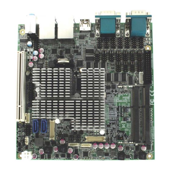
Chapter 1 Chapter 1 Introduction Overview The BEM-100F is a Mini-ITX form factor industrial motherboard combining the latest ® ® Intel Cedarview M/D processors D2550 with the high integration of the Intel NM10 chipset. Featured are 1x DDR3 800/1066 SO-DIMM up to 4GB, 7xUSB2.0, 2xGbE LAN, 2xSATA,1x HDMI, 1xVGA,1x mini PCIe slot, HD audio. -
Page 18: Product Specifications
1x 2x5 pitch 2.54mm pin header for 2 ports supported 1x 1x4 pitch 1.27mm wafer for 1 port supported 10x COM ports ( For BEM-100F ) 10x COM ports with power selection on COM1~COM10 1x COM port with RS-232/422/485 selection on COM 1... -
Page 19: Table 1 Bem-100F Series Specification
1x 2x2-pin ATX-4P power connector for single 12-24 V DC power input Power AT / ATX power mode supported, default is ATX mode 0ºC – 60ºC (For BEM-100F) Operation Temp. Certifications CE, FCC Class A Table 1 BEM-100F series Specification BEM-100F series User’s Manual... -
Page 20: Mechanical Dimensions
Chapter 1 Figure 1 Block Diagram Mechanical Dimensions ø ø ø : 3.5mm : 3.1mm *C- : 5.5mm BEM-100F series User’s Manual... -
Page 21: Figure 2 Mechanical Dimensions
Chapter 1 Figure 2 Mechanical Dimensions BEM-100F series User’s Manual... -
Page 22: Chapter 2 Hardware Settings
No.1. To move a jumper from one position to another, use needle-nose pliers or tweezers to pull the pin cap off the pins and move it to the desired position. BEM-100F series User’s Manual... -
Page 23: Jumper Settings And Pin Definitions
Chapter 2 Jumper Settings and Pin Definitions For jumper and connector locations, please refer to the diagrams below. Figure 4 Jumper and Connector Locations BEM-100F series User’s Manual... -
Page 24: Jumper Settings
JP17 Signal / Power Selection for COM10 JP18 MPCIE Activity LED Indication 10x COM ports ( For BEM-100F ) Table 3 JP1 USB Power Selection Jumper Status 1-2 Open USB power will be cut off in S4 & S5 state. -
Page 25: Table 6 Jp4 Panel & Backlight Power Selection For Lvds1
Panel Power = +3.3V Panel Power = +5V Pitch:2.54mm [YIMTEX 3362*03SAGR] Table 8 JP6 Backlight Power Enable Selection for LVDS2 Jumper Setting Status Backlight Enable Voltage = +3.3V Backlight Enable Voltage = +5V Active High Active Low Pitch:2.0mm[PINREX 222-97-03GBB1] BEM-100F series User’s Manual... -
Page 26: Table 9 Jp7 Backlight Power Enable Selection For Lvds1
Pin 9 = +12V 4-6 Short Pin 9 = +5V 6-8 Short Pin 9 = +5V 8-10 Short Pin 9 = RI Pitch:2.54mm [YIMTEX 3362*05SANGR] Table 11 JP18 MPCIE Activity LED Indication Description LED+ LED- Pitch:2.54mm [YIMTEX 3321*02SAGR(6T)] BEM-100F series User’s Manual... -
Page 27: Internal Connector Pin Assignment
Secondary 24-bit, 2-channel LVDS Panel Connector MPCIE1 Mini-PCIE Express v1.2 Socket 1 PCI1 PCI Slot SATA1 Serial ATA Port 0 Connector SATA2 Serial ATA Port 1 Connector LPT1 Parallel Port Pin Header 10x COM ports ( For BEM-100F ) BEM-100F series User’s Manual... -
Page 28: Table 12 Atx1 4-Pin Atx Power Input Connector
+5V / +12V ** +5V / +12V ** BL_EN*** Pitch:1.25mm [Townes Enterprise 1250W-07T1-V] *:BL_ADJ can be setting from 0V to 5V in BIOS setup. **:Backlight Power can be selected by JP4. ***:BL_EN can be selected by JP7. BEM-100F series User’s Manual... -
Page 29: Table 16 Cn2 Panel Backlight Wafer For Lvds2
Table 18 CN7 PS/2 Keyboard / Mouse Wafer Signal Name MSCLK MSDAT* KBDAT KBCLK Pitch:2.0mm [YIMTEX 503PW1*06ST-1R] Table 19 CN8 Digital Input / Output Pin Header Signal Signal +5VIO DIO_0 DIO_1 DIO_2 DIO_3 DIO_4 DIO_5 DIO_6 DIO_7 Pitch:2.54mm [YIMTEX 3362*05SANGR] BEM-100F series User’s Manual... -
Page 30: Table 20 Cn9 Sim Interface Wafer For Mpcie1
Table 23 CN12 Left Channel 2W Audio AMP Output Wafer Signal Name Speaker+ Speaker- Pitch:2.0mm [YIMTEX 503PW1*02STR] Table 24 CN13 USB2.0 Port 4, 5 Pin Header Signal Name Signal Name +USBVCC +USBVCC USB_A- USB_B- USB_A+ USB_B+ Pitch:2.54mm [YIMTEX 3362*05SANGR-09] BEM-100F series User’s Manual... -
Page 31: Table 25 Cn14 Usb2.0 Port 6 Wafer
Table 27 FP1 Front Panel 1 Pin Header Signal Signal Reset Button + Speaker + Reset Button - RSTBTN HDD LED + Internal Speaker- SPKR HDD LED - Speaker - HLED Pitch:2.54mm [YIMTEX 3362*04SANGR] Note:Internal Buzzer is enabled when Pin6-8 is shorted. BEM-100F series User’s Manual... -
Page 32: Table 28 Fp2 Front Panel 2 Pin Header
Table 29 LVDS1 Primary 24-bit, 1-channel LVDS Panel Connector Signal Name Signal Name VDD_EN +3.3V / +5V* TxclkA- TxclkA+ TxoutA0- TxoutA0+ TxoutA1- TxoutA1+ TxoutA2- TxoutA2+ TxoutA3- TxoutA3+ DDC_Data Pitch:1.25mm [HIROSE DF13-30DP-1.25(24)] *:LVDS1 panel power can be selected by JP4. BEM-100F series User’s Manual... -
Page 33: Table 30 Lvds2 Secondary 24-Bit, 2-Channel Lvds Panel Connector
+3.3V / +5V* TxclkB- TxclkA- TxclkB+ TxclkA+ TxoutB0- TxoutA0- TxoutB0+ TxoutA0+ TxoutB1- TxoutA1- TxoutB1+ TxoutA1+ TxoutB2- TxoutA2- TxoutB2+ TxoutA2+ TxoutB3- TxoutA3- TxoutB3+ TxoutA3+ DDC_Clock DDC_Data Pitch:1.25mm [HIROSE DF13-30DP-1.25(24)] *:LVDS2 panel power can be selected by JP5. BEM-100F series User’s Manual... -
Page 34: Table 31 Mpcie1 Mini-Pci Express V1.2 Socket 1
Ground +1.5V Ground SMB_CLK PETn0 SMB_DATA PETp0 Ground Ground USB_D- Ground USB_D+ +3.3VSB Ground +3.3VSB LED_WWAN# Ground LED_WLAN# Reserved LED_WPAN# Reserved +1.5V Reserved Ground Reserved +3.3VSB Height:9.9mm [FOXCONN AS0B226-S99Q-7H] *:These pins are connected to CN9 directly. BEM-100F series User’s Manual... -
Page 35: Table 32 Pci1 32-Bit / 33Mhz / 5V-Key Pci Slot
AD[01] AD[00] Ground AD[22] AD[21] AD[20] Reserved Reserved AD[19] Ground +3.3V AD[18] DIP PCI 60*2P 180D [DU 8790-20C0-1280] *:Reserved for second PCI master device. Table 33 SATA1 Serial ATA Port 0 Connector Signal Name [FOXCONN LD1807V-S52U] BEM-100F series User’s Manual... -
Page 36: Table 34 Sata2 Serial Ata Port 1 Connector
Table 34 SATA2 Serial ATA Port 1 Connector Signal Name [FOXCONN LD1807V-S52U] Table 35 LPT1 Parallel Wafer Signal Name Signal Name #AFD #ERR #INIT #SLIN #ACK BUSY SLCT DIP 26P 2R MALE 180° Pitch:2.54mm .Remove PIN No.26 [PINREX 210-72-13GB11] BEM-100F series User’s Manual... -
Page 37: Rear Panel Pin Assignments
GREEN LINE OUT PINK MIC IN [Foxconn JA33331-H11P-4F] Table 38 CN4 LAN1 & USB2.0 Port 0,1 Connector Signal Signal MDI[0]+ +USBVCC MDI[0]- USB_A- MDI[1]+ USB_A+ MDI[1]- MDI[2]+ +USBVCC MDI[2]- USB_B- MDI[3]+ USB_B+ MDI[3]- [UDE RU1-161F9WGF (XB)] BEM-100F series User’s Manual... -
Page 38: Table 39 Cn5 Lan2 & Usb2.0 Port 2,3 Connector
Table 40 HDMI1 HDMI Connector Signal TMDS Data2+ Ground TMDS Data2– TMDS Data1+ Ground TMDS Data1– TMDS Data0+ Ground TMDS Data0– TMDS Clock+ Ground TMDS Clock– Reserved Reserved DDC_CLK DDC_DATA Ground +5 V Power Hot Plug Detect [FOXCONN QJ3119C-WFB1-4F] BEM-100F series User’s Manual... -
Page 39: Table 41 Cn1 Crt Db-15 + Com3 Db-9 Connector
DCD, Data carrier detect RXD, Receive data TXD, Transmit data DTR, Data terminal ready GND, ground DSR, Data set ready RTS, Request to send CTS, Clear to send RI, Ring indicator D-SUB 9P(M)&15S(19.05mm(F)FOR PC99 FOLLOW PANTONE COLOR[FAN YING D201B1N01002N] BEM-100F series User’s Manual... -
Page 40: Table 42 Cn13 Rs-232 / 422 / 485 Port 1, 2 Connector
Half Duplex Full Duplex Port RS-232 RS-422 RS-485 RS-485 DATA- DATA+ Half Duplex Full Duplex Port RS-232 RS-422 RS-485 RS-485 DATA- DATA+ [FAN YING D20HB1102112PN] Note:RS-232 / 422 / 485 can be selected in BIOS setup. BEM-100F series User’s Manual... -
Page 41: Chapter 3 System Installation
When adding or removing expansion cards, make sure that you unplug the power supply first. Meanwhile, read the documentation for the expansion card to configure any necessary hardware or software settings for the expansion card, such as jumpers, switches or BIOS configuration. BEM-100F series User’s Manual... -
Page 42: Memory Module Installation
SO-DIMM. Lift it out of the socket. Make sure you store the SO-DIMM in an anti-static bag. The socket must be populated with memory modules of the same size and manufacturer. BEM-100F series User’s Manual... -
Page 43: Chapter 4 Ami Bios Setup
This chapter provides a description of the AMI BIOS. The BIOS setup menus and available selections may vary from those of your product. For specific information on the BIOS for your product, please contact BENECOM. NOTE: The BIOS menus and selections for your product may vary from those in this chapter. -
Page 44: Main Menu
F2: Previous Values Total Size 2048 MB F3: Optimized Defaults Frequency 1067 MHz (DDR3) F4 Save & Exit System date [Thu 03/08/2012] ESC Exit System time [15:58:19] Version 2.14.1219. Copyright (C) 2011, American Megatrends, Co., Ltd.. BEM-100F series User’s Manual... -
Page 45: Advanced Menu
Version 2.14.1219. Copyright (C) 2011, American Megatrends, Co., Ltd.. Onboard LAN 1 Controller Options: Disabled, Enabled Onboard LAN 1 Boot Options: Disabled, Enabled Onboard LAN 2 Controller Options: Disabled, Enabled Onboard LAN 2 Boot Options: Disabled, Enabled Audio Controller Options: Disabled, Enabled BEM-100F series User’s Manual... -
Page 46: Table 45 Advanced Menu - Display Configuration
LVDS Panel Type ■ Options: VBIOS Default, 800x600 18Bit 1CH 1024X768 18Bit 1CH 1280X1024 18Bit 1CH 1366X768 18Bit 1CH LVDS 1 Backlight Control – Voltage 【2.5V】 Options: 0.0V, 0.5V, 1.0V, 1.5V, 2.0V, 2.5V, 3.0V, 3.5V, 4.0V, 4.5V, 5.0V BEM-100F series User’s Manual... - Page 47 LVDS 1 Backlight Control – Voltage 【2.5V】 Options: 0.0V, 0.5V, 1.0V, 1.5V, 2.0V, 2.5V, 3.0V, 3.5V, 4.0V, 4.5V, 5.0V LVDS 2 Backlight Control – Voltage 【2.5V】 Options: 0.0V, 0.5V, 1.0V, 1.5V, 2.0V, 2.5V, 3.0V, 3.5V, 4.0V, 4.5V, 5.0V, BEM-100F series User’s Manual...
-
Page 48: Table 46 Advanced Menu -Power Management Configuration
Resume From S3 By PS/2 Mouse Options: Disabled, Enabled Resume By PCIE Device Options: Disabled, Enabled Resume By RTC Alarm Options: Disabled, Enabled EUP Power Saving Mode Options: Disabled, Enabled Watchdog Timer Configuration WDT Function [Disabled] ■ Options: Disabled, Enabled BEM-100F series User’s Manual... -
Page 49: Table 47 Advanced Menu -Cpu Advanced Configuration
F3: Optimized Defaults F4 Save & Exit ESC Exit Version 2.14.1219. Copyright (C) 2011, American Megatrends, Co., Ltd.. Hyper-Treading Options: Disabled, Enabled Execute Disable Bit Options: Disabled, Enabled Limit CPUID Maximum Options: Disabled, Enabled EIST Options: Disabled, Enabled BEM-100F series User’s Manual... -
Page 50: Table 48 Advanced Menu -Sata Configuration
192 PCI Bus Clocks 96 PCI Bus Clocks 224 PCI Bus Clocks 128 PCI Bus Clocks 248 PCI Bus Clocks VGA Palette Snoop Options: Disabled, Enabled PERR# Generation Options: Disabled, Enabled SERR# Generation Options: Disabled, Enabled BEM-100F series User’s Manual... -
Page 51: Table 50 Advanced Menu -Usb Configuration
F4 Save & Exit ESC Exit Version 2.14.1219. Copyright (C) 2011, American Megatrends, Co., Ltd.. Legacy USB Support Options: Disabled, Enabled, Auto EHCI hand-off Options: Disabled, Enabled Mass Storage Device Options: Auto, Floppy, Forced FDD, Hard Disk, CD-ROM BEM-100F series User’s Manual... -
Page 52: Table 51 Advanced Menu -Dio Configuration
Options: Output Low, Output High, Input DIO-3 Options: Output Low, Output High, Input DIO-4 Options: Output Low, Output High, Input DIO-5 Options: Output Low, Output High, Input DIO-6 Options: Output Low, Output High, Input DIO-7 Options: Output Low, Output High, Input BEM-100F series User’s Manual... -
Page 53: Table 52 Advanced Menu - Super Io Configuration
IO=3F8h; IRQ=3, 4, 5, 6, 7, 10, 11, 12; IO=2F8h; IRQ=3, 4, 5, 6, 7, 10, 11, 12; IO=3E8h; IRQ=3, 4, 5, 6, 7, 10, 11, 12; IO=2E8h; IRQ=3, 4, 5, 6, 7, 10, 11, 12; Serial Port Type Options: RS232, RS422, RS485 BEM-100F series User’s Manual... - Page 54 IO=3F8h; IRQ=3, 4, 5, 6, 7, 10, 11, 12; IO=2F8h; IRQ=3, 4, 5, 6, 7, 10, 11, 12; IO=3E8h; IRQ=3, 4, 5, 6, 7, 10, 11, 12; IO=2E8h; IRQ=3, 4, 5, 6, 7, 10, 11, 12 Serial Port 2 Type Options: RS232, RS422, RS485 BEM-100F series User’s Manual...
- Page 55 IO=3E8h; IRQ=3, 4, 5, 6, 7, 10, 11, 12; IO=2E8h; IRQ=3, 4, 5, 6, 7, 10, 11, 12 IO=2F0h; IRQ=3, 4, 5, 6, 7, 10, 11, 12 IO=2E0h; IRQ=3, 4, 5, 6, 7, 10, 11, 12 BEM-100F series User’s Manual...
- Page 56 IO=3E8h; IRQ=3, 4, 5, 6, 7, 10, 11, 12; IO=2E8h; IRQ=3, 4, 5, 6, 7, 10, 11, 12 IO=2F0h; IRQ=3, 4, 5, 6, 7, 10, 11, 12 IO=2E0h; IRQ=3, 4, 5, 6, 7, 10, 11, 12 BEM-100F series User’s Manual...
- Page 57 IO=3E8h; IRQ=3, 4, 5, 6, 7, 10, 11, 12; IO=2E8h; IRQ=3, 4, 5, 6, 7, 10, 11, 12 IO=2F0h; IRQ=3, 4, 5, 6, 7, 10, 11, 12 IO=2E0h; IRQ=3, 4, 5, 6, 7, 10, 11, 12 BEM-100F series User’s Manual...
- Page 58 IO=3E8h; IRQ=3, 4, 5, 6, 7, 10, 11, 12; IO=2E8h; IRQ=3, 4, 5, 6, 7, 10, 11, 12 IO=2F0h; IRQ=3, 4, 5, 6, 7, 10, 11, 12 IO=2E0h; IRQ=3, 4, 5, 6, 7, 10, 11, 12 BEM-100F series User’s Manual...
- Page 59 Version 2.14.1219. Copyright (C) 2011, American Megatrends, Co., Ltd.. Serial Port Options: Disabled, Enabled Change Settings Options: Auto, IO=260h; IRQ=11; IO=260h; IRQ=10, 11, 12; IO=268h; IRQ=10, 11, 12; IO=270h; IRQ=10, 11, 12; IO=278h; IRQ=10, 11, 12 BEM-100F series User’s Manual...
- Page 60 Version 2.14.1219. Copyright (C) 2011, American Megatrends, Co., Ltd.. Serial Port Options: Disabled, Enabled Change Settings Options: Auto, IO=268h; IRQ=11; IO=260h; IRQ=10, 11, 12; IO=268h; IRQ=10, 11, 12; IO=270h; IRQ=10, 11, 12; IO=278h; IRQ=10, 11, 12 BEM-100F series User’s Manual...
- Page 61 Version 2.14.1219. Copyright (C) 2011, American Megatrends, Co., Ltd.. Serial Port Options: Disabled, Enabled Change Settings Options: Auto, IO=270h; IRQ=11; IO=260h; IRQ=10, 11, 12; IO=268h; IRQ=10, 11, 12; IO=270h; IRQ=10, 11, 12; IO=278h; IRQ=10, 11, 12 BEM-100F series User’s Manual...
- Page 62 Version 2.14.1219. Copyright (C) 2011, American Megatrends, Co., Ltd.. Serial Port Options: Disabled, Enabled Change Settings Options: Auto, IO=278h; IRQ=11; IO=260h; IRQ=10, 11, 12; IO=268h; IRQ=10, 11, 12; IO=270h; IRQ=10, 11, 12; IO=278h; IRQ=10, 11, 12 BEM-100F series User’s Manual...
-
Page 63: Table 63 Advanced Menu - Super Io Configuration - Parallel Port
IO=278h; IRQ=5, 6, 7,10, 11, 12; IO=3BCh; IRQ=5, 6, 7,10, 11, 12; IO=378h; IRQ= IO=278h; IRQ= IO=3BCh; IRQ= Device Mode [Parallel Port Configuration] Options: Parallel Port Configuration, EPP Mode , ECP Mode, EPP Mode & ECP Mode BEM-100F series User’s Manual... -
Page 64: Table 64 Advanced Menu -H/W Monitor
F1: General Help F2: Previous Values F3: Optimized Defaults F4 Save & Exit ESC Exit Version 2.14.1219. Copyright (C) 2011, American Megatrends, Co., Ltd.. CPU Warning Temperature Options: Disabled, 80 ºC , 85 ºC, 90 ºC BEM-100F series User’s Manual... -
Page 65: Boot Menu
F4 Save & Exit ESC Exit Version 2.14.1219. Copyright (C) 2011, American Megatrends, Co., Ltd.. Full Screen LOGO Display Options: Disabled, Enabled Bootup Numlock State Options: On, Off Boot Option #1 Options: UEFI, SATA PM: Disabled BEM-100F series User’s Manual... -
Page 66: Security Menu
CMOS RAM. The CMOS RAM is sustained by an onboard backup battery and stays on even when the PC is turned off. When you select this option, a confirmation window appears. Select [Yes] to save changes and exit. BEM-100F series User’s Manual... - Page 67 Load Optimal Default values for all the setup values. This option allows you to load failsafe default values for each of the parameters on the Setup menus, which will provide the most stable performance settings. The F8 key can be used for this operation. BEM-100F series User’s Manual...
- Page 68 Chapter 5 Driver Installation If your BEM-100F series does not come with an operating system pre-installed, you will need to install an operating system and the necessary drivers to operate it. After you have finished assembling your system and connected the appropriate power source, power it up using the power supply and install the desired operating system.
- Page 69 Appendix A Appendix A DIO (Digital I/O) Sample Code //***************************************************************// //DIO sample code for BEM-100F //Please compile with Turbo C 3.0 to utilized the program //DIO GPIO pin define from SIO IT8783E // DIO_0 : GP50 DIO_4 : GP54 // DIO_1 : GP51...
- Page 70 Unlock_SIO(); outportb(INDEX_PORT, REG_LD); outportb(DATA_PORT, LD); Lock_SIO(); //--------------------------------------------------------------------------- void Set_SIO_Reg( int REG, int DATA) Unlock_SIO(); outportb(INDEX_PORT, REG); outportb(DATA_PORT, DATA); Lock_SIO(); //--------------------------------------------------------------------------- int Get_SIO_Reg(int REG) int Result; Unlock_SIO(); outportb(INDEX_PORT, REG); Result = inportb(DATA_PORT); Lock_SIO(); return Result; int main() BEM-100F series User’s Manual...
- Page 71 = %d\n",i ,Temp); system("pause"); //Set DIO_0~7 as Output //0:input 1:output Set_SIO_LD(0x07); RetVal = Get_SIO_Reg(0xCC); RetVal |= 0xFF; Set_SIO_Reg(0xCC, RetVal); //set DIO_0~7 to High printf("Set DIO_0~7 to High\n"); outportb(GPIOBASE, 0xFF); system("pause"); //set DIO_0~7 to Low printf("Set DIO_0~7 to Low\n"); BEM-100F series User’s Manual...
- Page 72 Appendix A outportb(GPIOBASE, 0x00); system("pause"); return 0; BEM-100F series User’s Manual...
- Page 73 Appendix B Appendix B WatchDog Timer Sample Code //============================================ //BEM-100F DOS Watchdog sample program //Please compile with Turbo C 3.0 to utilized the program //============================================ #Co., Ltd.lude<stdio.h> int main() int value; //Enter the MB PnP Mode outp(0x2E,0x87); outp(0x2E,0x01); outp(0x2E,0x55); outp(0x2E,0x55);...
- Page 74 Appendix B //Exit the MB PnP Mode outp(0x2E,0x02); outp(0x2F,0x02); return 0; BEM-100F series User’s Manual...
Need help?
Do you have a question about the BEM-100F and is the answer not in the manual?
Questions and answers