Sign In
Upload
Manuals
Brands
BENECOM Manuals
Motherboard
BEM-100F
BENECOM BEM-100F Manuals
Manuals and User Guides for BENECOM BEM-100F. We have
1
BENECOM BEM-100F manual available for free PDF download: User Manual
BENECOM BEM-100F User Manual (74 pages)
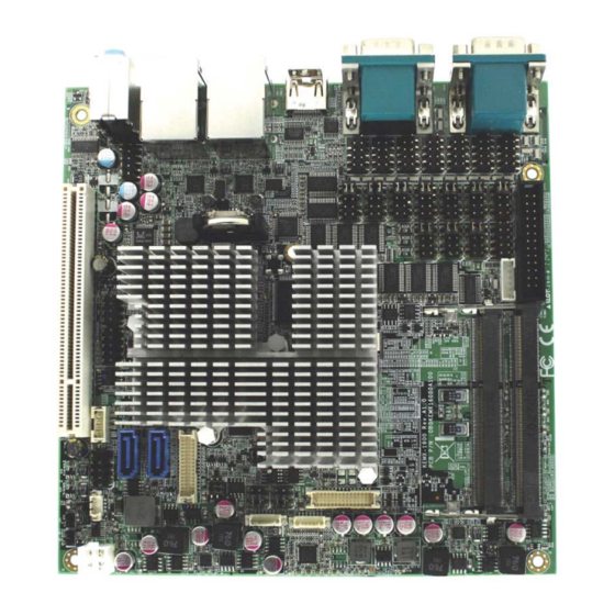
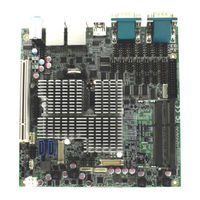
Industrial Motherboard in Mini-ITX form factor With Dual Core Intel Atom Processor D2550
Brand:
BENECOM
| Category:
Motherboard
| Size: 1 MB
Table of Contents
Content
3
Table of Contents
3
Figures
5
Tables
6
Before You Begin
9
Safety Instructions
9
When Working Inside a Computer
9
Preventing Electrostatic Discharge
10
How to Use this Guide
12
Preface
12
Regulatory Compliance Statements
12
Unpacking
12
Warranty Policy
13
Maintaining Your Computer
14
Chapter 1 Introduction
17
Overview
17
Product Specifications
18
Table 1 BEM-100F Series Specification
19
Mechanical Dimensions
20
Figure 1 Block Diagram
20
Figure 2 Mechanical Dimensions
21
Chapter 2 Hardware Settings
22
Overview
22
Figure 3 Jumper Connector
22
Jumper Settings and Pin Definitions
23
Figure 4 Jumper and Connector Locations
23
Jumper Settings
24
Table 2 Jumper List
24
Table 3 JP1 USB Power Selection
24
Table 4 JP2 RTC Reset Selection
24
Table 5 JP3 at / ATX Mode Selection
24
Table 6 JP4 Panel & Backlight Power Selection for LVDS1
25
Table 7 JP5 Panel & Backlight Power Selection for LVDS2
25
Table 8 JP6 Backlight Power Enable Selection for LVDS2
25
Table 9 JP7 Backlight Power Enable Selection for LVDS1
26
Table 10 JP8~JP17 Signal / Power Selection for COM1~COM10
26
Table 11 JP18 MPCIE Activity LED Indication
26
Internal Connector Pin Assignment
27
Table 12 ATX1 4-Pin ATX Power Input Connector
28
Table 13 BAT1 CR2032 Battery Holder
28
Table 14 COM4~COM10 RS-232 Port 4~10 Pin Header
28
Table 15 CN1 Panel Backlight Wafer for LVDS1
28
Table 16 CN2 Panel Backlight Wafer for LVDS2
29
Table 17 CN6 HDD Power Output Wafer
29
Table 18 CN7 PS/2 Keyboard / Mouse Wafer
29
Table 19 CN8 Digital Input / Output Pin Header
29
Table 20 CN9 SIM Interface Wafer for Mpcie1
30
Table 21 CN10 Azalia Front Audio Pin Header
30
Table 22 CN11 S/PDIF Input / Output Pin Header
30
Table 23 CN12 Left Channel 2W Audio AMP Output Wafer
30
Table 24 CN13 USB2.0 Port 4, 5 Pin Header
30
Table 25 CN14 USB2.0 Port 6 Wafer
31
Table 26 CN15 Right Channel 2W Audio AMP Output Wafer
31
Table 27 FP1 Front Panel 1 Pin Header
31
Table 28 FP2 Front Panel 2 Pin Header
32
Table 29 LVDS1 Primary 24-Bit, 1-Channel LVDS Panel Connector
32
Table 30 LVDS2 Secondary 24-Bit, 2-Channel LVDS Panel Connector
33
Table 31 MPCIE1 Mini-PCI Express V1.2 Socket 1
34
Table 32 PCI1 32-Bit / 33Mhz / 5V-Key PCI Slot
35
Table 33 SATA1 Serial ATA Port 0 Connector
35
Table 34 SATA2 Serial ATA Port 1 Connector
36
Table 35 LPT1 Parallel Wafer
36
Rear Panel Pin Assignments
37
Figure 5 Rear Panel IO
37
Table 36 Rear Panel Connector List
37
Table 37 AUDIO1, 3 Stack-Up Azalia Audio Phone Jack
37
Table 38 CN4 LAN1 & USB2.0 Port 0,1 Connector
37
Table 39 CN5 LAN2 & USB2.0 Port 2,3 Connector
38
Table 40 HDMI1 HDMI Connector
38
Table 41 CN1 CRT DB-15 + COM3 DB-9 Connector
39
Table 42 CN13 RS-232 / 422 / 485 Port 1, 2 Connector
40
Chapter 3 System Installation
41
Expansion Interfaces
41
Figure 6 Expansion Interfaces
41
Memory Module Installation
42
Figure 7 Align the SO-DIMM Memory Module with the Onboard Socket
42
Figure 8 Press down on the SO-DIMM Memory Module to Lock It in Place
42
Chapter 4 AMI BIOS Setup
43
Overview
43
Main Menu
44
Table 43 BIOS Main Menu
44
Advanced Menu
45
Table 44 Advanced Menu
45
Table 45 Advanced Menu - Display Configuration
46
Table 46 Advanced Menu -Power Management Configuration
48
Table 47 Advanced Menu -CPU Advanced Configuration
49
Table 48 Advanced Menu -SATA Configuration
50
Table 49 Advanced Menu -PCI BUS Driver Version V 2.05.02
50
Table 50 Advanced Menu -USB Configuration
51
Table 51 Advanced Menu -DIO Configuration
52
Table 52 Advanced Menu - Super IO Configuration
53
Table 53 Advanced Menu - Super IO Configuration - Serial Port
53
Table 63 Advanced Menu - Super IO Configuration - Parallel Port
63
Table 64 Advanced Menu -H/W Monitor
64
Boot Menu
65
Table 65 Boot Menu
65
Security Menu
66
Save & Exit Menu
66
Table 66 Security Menu
66
Table 67 Save & Exit Menu
66
Advertisement
Advertisement
Related Products
BENECOM BEM-100Q
Benecom BEM-100BYT2
BENECOM BEM-100B
BENECOM BEM-100C
BENECOM BNC-152
BENECOM BPC-203 SERIES
BENECOM BNC-15T-IP
BENECOM BNC-122
BENECOM BPC-201
BENECOM Categories
Motherboard
Industrial PC
Monitor
Computer Hardware
More BENECOM Manuals
Login
Sign In
OR
Sign in with Facebook
Sign in with Google
Upload manual
Upload from disk
Upload from URL