Advertisement
Available languages
Available languages
Quick Links
O W N E R ' S
1. Read this manual carefully before starting assemb ly. Read each step completely before beginning
each step.
2. Some smaller parts may be shipped inside larger parts. Check inside all parts and cartons
before assembling or ordering parts.
3. Do not tighten hardware until instructed to do so. If hardware is tighten too soon, mounting holes
may not align and parts may not easily fit togeth er. Leave locknuts slightly loose until you are instructed to
tighten them.
4. Tools required for assembly: Phillips Screwdriver, Adjustable Wrenches, Rubber Hammer, 8mm Wrench,
and 10mm wrench.
5. To make assembly as easy as possible, place all parts of the table in a cleared area and remove the packaging
material. Do not remove parts from bags until you are ready to assemble that part. Do not dispose of the
packing material until assembly is completed. For he lp in identifying parts, use the the Parts List, Hardware
Identification and the Exploded Drawings.
6. An electric screwdriver is helpful in assembly. However, please set at low torque and use caution because you
could overtighten the hardware and strip the screws.
Please Do Not Return This Product To The Store!
Contact Escalade Sports customer service department at:
Phone:
1-866-873-3528
Fax:
1-866-873-3533
E-mail:
tabletennis@escaladesports.com
Mailing Address(correspondence only):
Escalade Sports
PO box 889
Evansville, IN 47706
Please visit our World Wide Web site at: www.escaladespo rts.com
ON-LINE TROUBLE SHOOTING
ON-LINE PARTS REQUESTS
ADDITIONAL ESCALADE SPORTS PRODUCT INFORMANTION
R
Escalade Sport products may be manufactured and/or licensed under the following patents.
6120397, 5816957, 5769744, 5119741, 4911085, 4717157, D460140, D420563
Additional patents may be pending. One or more of the listed patents and/or pending patents may cover specific product.
R
M A N U A L
Toll-Free!
Toll-Free!
TECHNICAL ASSISTANCE
FREQUENTLY ASKED QUESTIONS
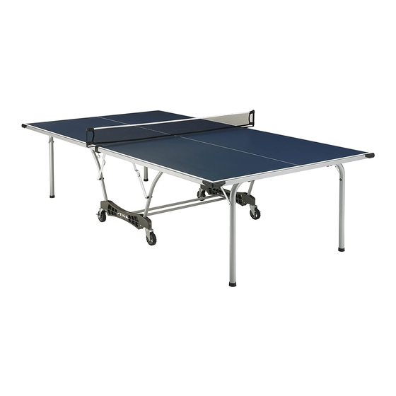
TABLE TENNIS TABLE
MODEL NO.
T8561
2014 Escalade Sports
C
2L-5057-00
R
Advertisement

Related Manuals for ESCALADE STIGA T8561


Summary of Contents for ESCALADE STIGA T8561
- Page 1 ADDITIONAL ESCALADE SPORTS PRODUCT INFORMANTION 2L-5057-00 Escalade Sport products may be manufactured and/or licensed under the following patents. 6120397, 5816957, 5769744, 5119741, 4911085, 4717157, D460140, D420563 Additional patents may be pending. One or more of the listed patents and/or pending patents may cover specific product.
- Page 2 IMPLIED WARRANTIES OF MERCHANTABILITY AND FITNESS FOR A PARTICULAR PURPOSE, ARE LIMITED IN DURATION TO THE ABOVE THREE (3) YEAR WARRANTY PERIOD. ESCALADE® SPORTS SHALL NOT BE LIABLE FOR LOSS OF USE OF THE PRODUCT OR OTHER CONSEQUENTIAL OR INCIDENTAL COSTS, EXPENSES OR DAMAGES INCURRED BY THE CONSUMER OF ANY OTHER USE.
-
Page 3: Hardware Identification
HARDWARE IDENTIFICATION 1/4-20 X 2 1/4 Phillips Rd. Hd. Bolt (4 pieces) 1/4-20 X 2 Carriage Bolt (4 pieces) #10-24 X 3/4 Thumb Screw (4 pieces) #10-24 X 2" Phillips Rd. Hd. Bolt (4 pieces) #8-32 X 1 1/4 Phillips Rd. Hd. Sms (8 pieces) #8 X 5/8 Phillips Rd. - Page 4 NOTE: If casters came pre-assembled on Caster Beam (#8), skip to Step 2. 1. Slide a Caster Wheel with Lock (#30) into Caster Beam READ AND FOLLOW ALL ASSEMBLY, OPERATING, as shown in FIGURE 1. On the other end of the Caster fAND SAFETY INSTRUCTIONS CAREFULLY.
-
Page 5: Hardware Needed
3. Attach four Strut Tubes (#4) to Caster Beam Assembly with four Carriage Bolts (#10) and four Locknuts (#14) READ AND FOLLOW ALL ASSEMBLY, OPERATING, as shown in FIGURE 3. Tighten nuts snug but DO NOT AND SAFETY INSTRUCTIONS CAREFULLY. AT LEAST over tighten. - Page 6 4. A) Attach two 1" Plastic Clips (#23) to bottom of aluminum top assembly using four Screws (#15) as shown in FIGURE 4 and DETAIL B. B) Attach U-Leg (#1) with two 1-1/2" Plastic Tube Brackets (#27) as shown in FIGURE 4 and DETAIL A.
- Page 7 5. A) Attach one LH short Hinge & Mounting Bracket Assembly (#18) using four Screws (#15) as shown in DETAIL C. Attach one RH short Hinge & Mounting Bracket Assembly (#6) using four Screws (#15) as shown in FIGURE 5. Attach two Long Hinge & Mounting Bracket Assemblies (#5) using eight Screws (#15) as shown in DETAIL D &...
- Page 8 6. Attach table top to base assembly. Pivot Strut Tubes (#4) up and then with at least one adult on each side of table AT LEAST TWO (2) ADULTS ARE NEEDED TO top, lift top and align ends of U-support Tube (#3) with COMPLETE THE REST OF THIS ASSEMBLY! WHEN tops of strut tubes on caster beams as shown in ASSEMBLING TOPS TO BASE, HANDLE TOP...
- Page 9 7. Attach U-Support (#3) and Strut Tubes (#4) using two Screws (#15) as shown in FIGURE 7. Note: If hinge (#5) is positioned as shown in DETAIL E, you will have to rotate the hinge to the position shown in Detail F.
- Page 12 Replacement PartsList for Model Number T8561 Key# Part# Description Qty. 8S-4577-02 U-Leg - Silver 4A-7910-00 Aluminum Top Assembly - T8561 8S-6871-01 U-Support - Silver 8S-4579-03 Strut Tube - Silver 4A-5577-00 Long Hinge & Mounting Bracket Assembly 4A-5579-00 RH Short Hinge & Mounting Bracket Assembly 4A-5430-00 Cross Tube 3M-8909-13...
-
Page 13: Número De Modelo
MÁS INFORMACIÓN SOBRE PRODUCTOS DE ESCALADE® SPORTS 2L-5057-00 Los productos Escalade® Sports se pueden fabricar y/o producir bajo las siguientes patentes. 6120397, 5816957, 5769744, 5119741, 4911085, 4717157, D460140, D420563 Puede haber patentes en trámite. Una o más patentes mencionadas y/o en trámite pueden cubrir productos específicos. - Page 14 O por correo electrónico a: tabletennis@escaladesports.com Fuera de los gastos de envío, no se impondrá cargo alguno por la reparación o reemplazo de los productos en garantía. ESCALADE® SPORTS recomienda asegurar los Productos por su valor antes del envío. LIMITACIÓN DE LA GARANTÍA: TODA GARANTÍA ORIGINADA EN ESTA VENTA, INCLUYENDO EN FORMA NO TAXATIVA, LAS GARANTÍAS IMPLÍCITAS DE COMERCIALIZACIÓN Y APTITUD PARA UN FIN ESPECÍFICO, TENDRÁ...
- Page 15 IDENTIFICADOR DE TORNILLOS 1/4-20 X 2 1/4 Tornillo Phillips (4 piezas) 1/4-20 X 2 Tornillo de Carruaje (4 piezas) #10-24 X 3/4 Tornillo de Mariposa (4 piezas) #10-24 X 2" Tornillo Phillips (4 piezas) #8-32 X 1 1/4 Tornillo Phillips (8 piezas) #8 X 5/8 Tornillo Phillips (100 piezas) (para Lamina de Metal) (para Lamina de Metal)
- Page 16 NOTA: Si las llantas ya vienen ensambladas a los carriles empiece con el paso 2. ADVERTENCIA! 1. Inserte una Llanta con Seguro (#30) dentro del Carril como se muestra en la FIGURA 1. En el otro extremo LEA Y SIGA TODAS LAS INSTRUCCIONES DEL del Carril inserte una Llanta sin Seguro (#9).
- Page 17 3. Una cuatro Tubos Estructurales (#4) a el Carril ADVERTENCIA! ensamblado utilizando cuatro Tornillos de Carruaje LEA Y SIGA TODAS LAS INSTRUCCIONES DEL (#10) y cuatro Tuercas de Seguridad (#14) como se ENSAMBLADO, LAS OPERACIONES Y LAS INSTRUCCIONES muestra en la FIGURA 3. Apriete las tuercas bien pero DE SEGURIDAD.
- Page 18 A) Instale los dos Clips de Plástico de 1” (#23) en la parte de abajo del tablero de aluminio utilizando cuatro tornillos (#15) como se muestra en la FIGURA 4 y en el DETALLE B. B) Instale la pata en “U” (#1) con dos Abrazaderas de Plástico para el tubo de 1-1/2” (#27) como se muestra en la FIGURA 4 y el DETALLE A.
- Page 19 A) Instale una Bisagra (corta)- Mano Izquierda (#18) utilizando cuatro tornillos (#15) como se muestra en el DETALLE C. Instale una Bisagra (corta) – Mano Derecha (#6) utilizando cuatro tornillos (#15) como se muestra en la FIGURA 5. Instale las dos Bisagras con soporte de montaje (Largas) (#5) utilizando ocho tornillos (#15) como se muestra en el DETALLE D y la FIGURA 5.
- Page 20 Una el Tablero a la base ensamblada. Mueva los Tubos ADVERTENCIA! Estructurales (#4) hacia arriba y después con por lo menos un adulto en cada lado de la mesa, levante y alinee las POR LO MENOS SE REQUIEREN DOS (2) ADULTOS PARA TERMINAR EL RESTO DEL ENSAMBLADO! orillas del Tubo de Soporte-U (#3) a las puntas de los Tubos CUANDO ENSAMBLE LOS TABLEROS A LA BASE,...
- Page 21 7. Atornille el Tubo del Soporte-U (#3) a los Tubos Estructurales (#4) con los dos Tornillos (#15) como se muestra en Figura 7. Nota: Si la Bisagra (#5) esta colocada como se muestra en Detalle E, usted tendrá que girar la bisagra a la posición que se muestra en Detalle F. NO desatornille la bisagra, usted puede girar la bisagra sin desatornillarla de la mesa.
- Page 22 INSTRUCIONES PARA ABRIR Y CERRAR LA MESA ADVERTENCIA! LAS CORRIENTES DE AIRE PUEDEN TIRAR O ABRIR SU MESA DE REPENTE: GUÁRDELA EN UN ÁREA PROTEGIDA. PONGA ATENCIÓN AL ABRIR Y AL CERRAR LA MESA. MENORES DE EDAD QUE NO SABEN EL USO APROPIADO DE LAS INSTRUCCIONES NO SE LES DEBE PERMITIR ABRIR Y CERRAR LA MESA.
- Page 24 Lista de partes reemplazables para el modelo T8561 # de Ref. # de Parte Descripción Cant. 8S-4577-02 Pata en U - Color Plata 4A-7910-00 Tablero de Aluminio Ensamblado - T8561 8S-6871-01 Tubo de Soporte en U - Color plata 8S-4579-03 Tubo Estructural - Color Plata 4A-5577-00 Bisagra con soporte de montaje (Larga)
Need help?
Do you have a question about the STIGA T8561 and is the answer not in the manual?
Questions and answers