
Related Manuals for Bard YA302


Summary of Contents for Bard YA302
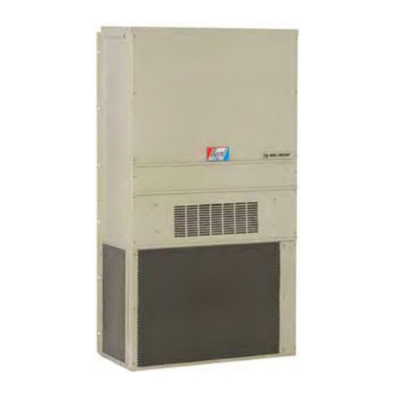
- Page 1 WALL MOUNTED PACKAGED INSTALLATION AIR CONDITIONER INSTRUCTIONS YA302 Models: YA372 MIS-383 Manual No.: 2100-461 Supersedes: Date: 06-20-05 © Copyright 2005...
-
Page 2: Table Of Contents
Contents Start Up Getting Other Information and Publications ..1 Important Installer Note ......... 13 High Pressure Switch ..........13 Wall Mount General Information Three Phase Scroll Compressor Start Up Air Conditioner Wall Mount Model Nomenclature ..2 Information ............. 13 Shipping Damage ............ -
Page 3: Getting Other Information And Publications
Getting Other Information and Publications FOR MORE INFORMATION, CONTACT These publications can help you install the air conditioner or heat pump. You can usually find these at THESE PUBLISHERS: your local library or purchase them directly from the publisher. Be sure to consult current edition of each ACCA Air Conditioning Contractors of America standard. -
Page 4: Wall Mount General Information
WALL MOUNT GENERAL INFORMATION AIR CONDITIONER WALL MOUNT MODEL NOMENCLATURE 2 – MODEL CONTROL MODULES REVISIONS NUMBER (See Spec. Sheet S3208) CAPACITY VOLTS & PHASE 30 - 2½ Ton COIL OPTIONS COLOR OPTIONS A - 230/208/60/1 37 - 3 Ton X - Standard X - Beige (Standard) B - 230/208/60/3... -
Page 5: Figure 1 Unit Dimensions
Manual 2100-461 Page... -
Page 6: Shipping Damage
TABLE 3 ELECTRIC HEAT TABLE - - - - - - - - - - - - - - - - - - - - - - - - - - - - - - - - - - - - - - - - - - - - -... -
Page 7: Duct Work
5/8 inches. Any grille that meets the 5/8 inch louver criteria may be used. It is recommended that Bard Return Air Grille Kit RG-2 through RG-5 or RFG-2 through RFG-5 be installed when no return duct is used. Contact distributor or factory for ordering information. -
Page 8: Installation Instructions
INSTALLATION INSTRUCTIONS 6. Position unit in opening and secure with 5/16 lag WALL MOUNTING INFORMATION bolts; use 7/8 inch diameter flat washers on the lag 1. Two holes, for the supply and return air openings, bolts. must be cut through the wall as shown in Figure 3. 7. -
Page 9: Wiring - Low Voltage Wiring
WIRING — LOW VOLTAGE WIRING The electrical data lists fuse and wire sizes (75ºC copper) for all models, including the most commonly 230/208V, 1 phase and 3 phase equipment dual primary used heater sizes. Also shown are the number of field voltage transformers. -
Page 10: Figure 3 Mounting Instructions
FIGURE 3 MOUNTING INSTRUCTIONS NOTE: It is recommended that a bead of silicone caulking be placed behind the side mounting flanges and under the top flashing at the time of installation. Manual 2100-461 Page... -
Page 11: Figure 4 Wall-Mounting Instructions
FIGURE 4 WALL-MOUNTING INSTRUCTIONS SEE FIGURE 3 – MOUNTING INSTRUCTIONS MIS-548 FIGURE 5 WALL-MOUNTING INSTRUCTIONS SEE UNIT DIMENSIONS, FIGURE 1, FOR ACTUAL DIMENSIONS SEE FIGURE 1 FOR DUCT DIMENSIONS MIS-549 Manual 2100-461 Page... -
Page 12: Figure 6 Common Wall-Mounting Installations
FIGURE 6 COMMON WALL-MOUNTING INSTALLATIONS MIS-550 Manual 2100-461 Page... -
Page 13: Figure 7 Electric Heat Clearances
FIGURE 7 ELECTRIC HEAT CLEARANCE Side section view of supply air duct for wall mounted unit showing 1/4 inch clearance to combustible surfaces. MIS-277 WARNING WARNING • A minimum of 1/4 inch clearance must be maintained between the supply air duct and combustible materials. -
Page 14: Figure 8 Low Voltage Wiring
FIGURE 8 LOW VOLTAGE WIRING Manual 2100-461 Page... -
Page 15: Start Up
START UP IMPORTANT INSTALLER NOTE The direction of rotation of the compressor may be changed by reversing any two line connections to the For improved start-up performance, wash the indoor coil unit. with a dishwasher detergent. PHASE MONITOR HIGH PRESSURE SWITCH All units with three phase compressors are equipped The YA372 models are supplied with a remote reset with a 3 phase line monitor to prevent compressor... -
Page 16: Compressor Control Module
COMPRESSOR CONTROL MODULE Alarm Relay Output The compressor control module is optional on the Alarm terminal is output connection for applications models covered by this manual. The compressor control where alarm relay is employed. This terminal is is an anti-short cycle/lockout timer with high and low powered whenever compressor is locked out due to HPC pressure switch monitoring and alarm relay output. -
Page 17: Figure 9 Fan Blade Setting
TROUBLESHOOTING FAN BLADE SETTING DIMENSIONS The suction line temperatures in Table 8 are based upon 80ºF dry bulb/67ºF wet bulb (50 percent R.H.) Shown in the drawing below are the correct fan blade temperature and rated airflow across the evaporator setting dimensions for proper air delivery across the during cooling cycle. -
Page 18: Cooling Pressures
TABLE 12 COOLING PRESSURE Outdoor Temperature °F Low side pressure ± 2 psig High side pressure ± 5 psig Tables are based upon rated CFM (airflow) across the evaporator coil and should be found under section titled "Refrigerant Charge" elsewhere in manual. If there is any doubt as to correct charge being in the system, the charge should be removed, system evacuated and recharged to serial plate instructions. -
Page 19: Optional Accessories
TABLE 13 OPTIONAL ACCESSORIES l a i i t n t a l i t n t a l i t n t a l t i u t i u t i u These heater packages are not suitable for installation in top outlet models. NOTE: Top outlet models are available only as factory built.
Need help?
Do you have a question about the YA302 and is the answer not in the manual?
Questions and answers