
Related Manuals for Daikin D2CNL-A1A


Summary of Contents for Daikin D2CNL-A1A
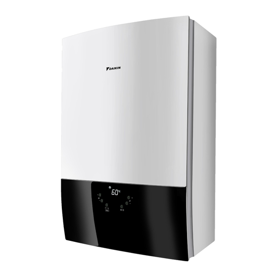
- Page 1 Installation Manual Wall-mounted condensing boiler Installation Manual English Wall-mounted condensing boiler D2CNL024A1AA...
- Page 2 2P475131-5H...
-
Page 3: Table Of Contents
Damage caused by non- Underfloor heating requirements..........11 observance of these instructions are not under the responsibility of Residual pump lift graph............11 Daikin. Connections ................11 4.8.1 Piping connections............11 ▪ The original documentation is written in English. All other languages are translations. -
Page 4: Symbols On The Package
Country of destination(s) Serial number About the unit Appliance type Efficiency class This Daikin unit is a wall-mounted gas-fired condensing boiler that Gas category Gas type and supply pressure can supply heat to central heating systems, as well as supply PIN number domestic hot water. -
Page 5: Dimensions
3 About the unit Front view and right side view Pump anti-blockage system: The pump operates for 30 seconds every 24 hours during long periods of inactivity to ensure it does not get stuck. To enable this function, the unit must be connected to the power supply. -
Page 6: Components
3 About the unit Components Automatic air vent (heat exchanger) Flow temperature sensor Expansion vessel Gas valve Heat exhanger 3-way valve motor Domestic hot water temperature sensor Plate heat exchanger Safety valve (3 bar) Condensate trap Ignition transformer Flue gas temperature sensor Burner hood Ignition electrode Ionisation electrode... -
Page 7: Technical Specifications
3 About the unit Technical specifications Technical specifications Unit D2CNL024A1AA Heat Input Range(Qn) 4~23.5 Nominal Heat Output Range (Pn) at 80-60°C 3.8~22.8 Nominal Heat Output Range (Pn) at 50-30°C 4.4~24 Efficiency (30% partial load at 30°C return temperature) Central Heating Circuit Operating Pressure (min./max.) 0.6 / 3.0 Heating Circuit Temperature Interval (min./max.) -
Page 8: Installation
4 Installation Low temperature means for condensing boilers 30°C, for low-temperature boilers 37°C and for other heaters 50°C return temperature (at heater inlet). Installation To open the unit WARNING ONLY qualified competent persons are allowed to open the unit. Certain actions explained in this document, such as gas conversion, optional equipment connection, require that the front cover is opened. -
Page 9: Installation Site Requirements
4 Installation Minimum installation clearances Installation site requirements WARNING The boiler MUST be installed by a qualified installer in accordance with local and national regulations. WARNING The following instructions shall be observed when determining the installation site. ▪ Mount this unit on vertical, flat walls only. Minimum allowable clearances a, sides 10 mm... -
Page 10: To Mount The Unit
4 Installation To mount the unit Central heating system requirements 1 The mounting template shows the position for the horizontal flue. If there is no hole in the wall for the flue piping, drill one. If Expansion vessel sizing there is already a hole in the wall for the flue piping, you can The boiler is equipped with an expansion vessel that has initial use this hole as a starting point to determine the position of the charge pressure of 1 bar. -
Page 11: Underfloor Heating Requirements
Daikin accepts no liability for any such damage or ineffectiveness caused by using inappropriate additive. Underfloor heating requirements Underfloor heating systems apparently require higher flow rate and Central heating return connection, 3/4"... -
Page 12: Guidelines When Connecting The Water Piping
4 Installation In case gas piping is adjacent to the wall and is to be connected to ▪ The system must be air-free to protect the boiler. There are two the gas pipe connection of the boiler with an elbow, enough space automatic air vents on the boiler, one at heat exchanger, the other for taking out the condensate trap must be left. -
Page 13: Guidelines When Connecting Options To The Boiler
4 Installation PG 9 PG 9 PG 7 PG 7 ▪ Power supply cable must be equivalent to H05RN-F (2451EC57) as minimum requirement. ▪ The boiler is not approved to be operated at altitudes above 2000 meters above sea level. Observe the point mentioned below when wiring to the power supply terminal board. -
Page 14: Wiring Diagram
4 Installation 4.8.6 Wiring diagram DANGER: RISK OF ELECTROCUTION Disconnect the power supply for more than 10 minutes before servicing Ext2 L Ext3* L NTC4 NTC3 NTC2 3WV1 PCB1 NTC1 NTC5 WPS1 Installation Manual D2CNL024A1AA Wall-mounted condensing boiler 3P469346-12R – 2021.09... -
Page 15: Guidelines When Connecting The Condensate Piping
4 Installation Symbols: WARNING Item Description The condensate trap outlet shall NOT be modified or blocked. Option Wiring depending on model CAUTION Switch box The condensate discharge piping diameter must be large enough so as not to restrain the condensate water flow. Earth wiring WARNING Wire number 15... -
Page 16: Guidelines When Connecting The Boiler To The Flue Gas System
4 Installation Open end direct into gully, below ground but above water CAUTION level Once the flue system has been installed and the appliance Sink, basin, bath or shower commissioned, the installer should observe the plume NOTICE direction. Particular attention should be drawn to plume vapour reentering the gas boiler via the air intake. - Page 17 4 Installation Equivalent length of options 90° elbow 60/100 mm 1.5 m 45° elbow 60/100 mm 1.0 m 30° elbow 60/100 mm 1.0 m 90° elbow 80/125 mm 1.5 m 45° elbow 80/125 mm 1.0 m 30° elbow 80/125 mm 1.0 m 60/100 flue length can be increased up to 17.9 metres by adjusting the parameter.
- Page 18 ▪ Condensate flow into the unit is allowed. system must be obtained via Daikin. Type C53x (twin pipes flue system) Air supply and flue gas discharge from / to atmosphere in areas of different pressure.
- Page 19 CE marking. The connection between the boiler and the shaft and, the connection between the boiler and the air intake system must be obtained via Daikin. In C83x type units, condensate flow into the unit is not allowed.
- Page 20 Flue parts order codes Extension duct 60 mm 500 mm DREXDUC0500AA 1000 mm DREXDUC1000AA Required flue kits and/or additional parts can be ordered from Daikin with the order codes given in the table below: Flue part Order code Wall terminal kit 60/100 (C13x) DRWTER60100AA...
-
Page 21: To Fill The System With Water
5 Commissioning Fill the condensate trap by pouring 0.2 litres of water from the boiler To fill the system with water flue outlet. CAUTION Water filling must be done while the boiler is in standby mode. After all system connections are performed with care, perform the following steps: 1 Connect the unit to the main power supply. -
Page 22: To Commission The Central Heating
6 Hand-over to the user emissions Unit Value Emission at maximum heat input 9.3 ± 0.2 (G20) Emission at minimum heat input 8.7 ± 0.2 (G20) If emission at maximum heat input is not in limits, turn the adjustment screw (a) anticlockwise to increase CO2 or clockwise to decrease CO2. - Page 23 6 Hand-over to the user ▪ Explain and demonstrate the function of temperature controls, radiator valves etc., for the economic use of the system. ▪ Explain the function of the boiler error mode. Emphasise that if an error is indicated refer to "Error codes" in the operation manual. ▪...
- Page 24 DAIKIN ISITMA VE SOĞUTMA SİSTEMLERİ SAN.TİC. A.Ş. Gülsuyu Mahallesi, Fevzi Çakmak Caddesi, Burçak Sokak, No:20, 34848 Maltepe İSTANBUL / TÜRKİYE Tel: 0216 453 27 00 Faks: 0216 671 06 00 Çağrı Merkezi: 444 999 0 Web: www.daikin.com.tr 3P469346-12R 2021.09 Verantwortung für Energie und Umwelt...
Need help?
Do you have a question about the D2CNL-A1A and is the answer not in the manual?
Questions and answers
where is the flue sample point