
Subscribe to Our Youtube Channel
Related Manuals for Fluke 52120A-C


Summary of Contents for Fluke 52120A-C
- Page 1 52120A Transconductance Amplifier Users Manual February 2012 © 2012 Fluke Corporation. All rights reserved.Specifications are subject to change without notice. All product names are trademarks of their respective companies.
-
Page 3: Table Of Contents
Table of Contents Chapter Title Page Introduction and Specifications ............1-1 Introduction ......................1-3 How to Contact Fluke ..................1-3 Safety Information ..................... 1-4 Symbols ......................1-5 Protective Earth (Grounding) ................ 1-6 Instruction Manuals ................... 1-6 52120A Getting Started Manual ..............1-6 52120A Users Manual ................... - Page 4 52120A Users Manual 52120A/COIL 3 KA 25-Turn Coil ..............1-21 52120A/COIL 6 KA 50-Turn Coil ..............1-21 Front-Panel Operation ................ 2-1 Introduction ......................2-3 Notes on Product Use ..................2-3 Accuracy ......................2-3 Potential Measurement Errors ............... 2-4 Leakage Paths.................... 2-4 Common-Mode Current ................
- Page 5 Contents (continued) Calibration .................... 5-1 Introduction ......................5-3 Calibration Correction Factors ..............5-3 Equipment Required ..................5-3 Initial Setup and Input Zero Adjustments ............5-3 Calibration Verification – Standalone Mode ..........5-5 Equipment Setup ..................5-7 2 Amp Range Verification ................ 5-7 20 Amp Range Verification ..............
- Page 6 52120A Users Manual...
- Page 7 Page 1-1. Symbols ........................1-5 1-2. Standard Equipment ....................1-7 1-3. Line Power Cord Types Available from Fluke ............1-9 1-4. Front-Panel Features ....................1-10 1-5. Rear-Panel Features ....................1-12 1-6. Maximum Voltage and Current on Input Terminals ..........1-13 1-7.
- Page 8 52120A Users Manual...
- Page 9 List of Figures Figure Title Page 1-1. Front-Panel View ....................1-10 1-2. Rear-Panel View ....................1-12 2-1. Connections for Reduced Common-Mode Interference ........2-5 2-2. Product Connections to a Watthour Meter ............. 2-7 2-3. Status Indicators ..................... 2-9 2-4. 5520A and 52120A Connections ................2-11 2-5.
- Page 10 52120A Users Manual viii...
-
Page 11: Introduction And Specifications
Chapter 1 Introduction and Specifications Title Page Introduction ......................1-3 How to Contact Fluke ..................1-3 Safety Information ....................1-4 Symbols ......................1-5 Protective Earth (Grounding) ................1-6 Instruction Manuals ..................... 1-6 52120A Getting Started Manual ..............1-6 52120A Users Manual ..................1-6 How to Unpack and Examine the Product ............ - Page 12 52120A Users Manual...
-
Page 13: Introduction
• Japan: +81-3-6714-3114 • Singapore: +65-6799-5566 • China: +86-400-810-3435 • Brazil: +55-11-3759-7600 • Anywhere in the world: +1-425-446-6110 To see product information and download the latest manual supplements, visit Fluke Calibration’s website at www.flukecal.com To register your product, visit http://flukecal.com/register-product. -
Page 14: Safety Information
52120A Users Manual Safety Information This Product complies with: • EN/IEC 61010-1:2010 • CAN/CSA C22.2 No. 61010-1-04 • ANSI/UL 61010-1:2004 • EN 61326-1:2006 In this manual, a Warning identifies conditions and procedures that are dangerous to the user. A Caution identifies conditions and procedures that can cause damage the Product or the equipment under test. -
Page 15: Symbols
Conforms to European Union Protective earth directives. Risk of Danger. Important information. Hazardous voltage See manual. Earth ground Conforms to relevant Australian EMC requirements. Do not dispose of this product as unsorted municipal waste. Go to Fluke’s website for recycling information. -
Page 16: Protective Earth (Grounding)
52120A Getting Started Manual (PN 3977724) One of each manual shown above is shipped with the instrument. You can order more copies of the manuals from Fluke. To learn more on how to place an order, refer to the How to Contact Fluke section. -
Page 17: How To Unpack And Examine The Product
If it becomes necessary to ship the Product, use the container and inserts it was initially shipped in, if possible. If it is not available, you can get a transit case from Fluke. This container is applicable for most handling conditions, but gives less shock protection than the initial shipping container. -
Page 18: How To Connect The Product To Mains Power
Because the Product can pull more current than a standard 10 A IEC connector, the Product has a 16 A power connector on the rear panel. A mains power cord with 16 A capacity is also supplied with the Product. Table 1-3 is a list of power cord types available from Fluke. - Page 19 Introduction and Specifications How to Connect the Product to Mains Power Table 1-3. Line Power Cord Types Available from Fluke Country Fluke Part Number 1998167 Europe 1998171 Australia, New Zealand 1998198 China 4121791 USA, Japan 1998209 Brazil 3841358 Other (no plug fitted)
-
Page 20: Front-Panel Features
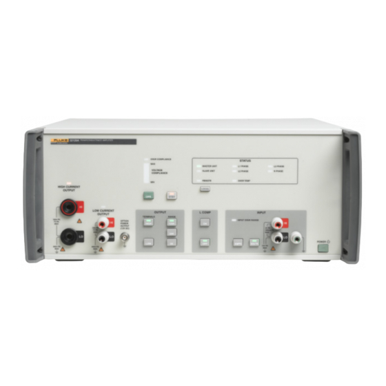
52120A Users Manual Front-Panel Features Table 1-4 is a list of front-panel controls and connections shown in Figure 1-1. 52120A TRANSCONDUCTANCE AMPLIFIER OVER COMPLIANCE STATUS MASTER UNIT L1 PHASE L3 PHASE VOLTAGE SLAVE UNIT N PHASE L2 PHASE COMPLIANCE REMOTE OVER TEMP HIGH CURRENT LOCAL... - Page 21 Introduction and Specifications Front-Panel Features Table 1-4. Front-Panel Features (cont.) Item Description Mains Power Switch The power switch turns the power on and off. The switch is a latching push-push type. When the switch is latched in, power is on. Note The front panel power switch operates electronically and is not an isolation switch.
-
Page 22: Rear-Panel Features
52120A Users Manual Rear-Panel Features Table 1-5 is a list of rear-panel controls and connections shown in Figure 1-2. gpp002.eps Figure 1-2. Rear-Panel View Table 1-5. Rear-Panel Features Item Description Main Power ON/OFF Switch This is the mains isolating switch. ... -
Page 23: Input And Output Connections
Introduction and Specifications Input and Output Connections Table 1-5. Rear-Panel Features (cont.) Item Description The CALIBRATION ENABLE / NORMAL switch is used to write enable and disable the nonvolatile memory that stores calibration constants. See the Calibration section of this Manual to learn more about calibration of the Product. -
Page 24: Output Terminals
52120A Users Manual Output Terminals There are two sets of output terminals on the Product. They are not referenced to ground. Each of the four terminals can be connected to a signal source with a maximum voltage of 850 V pk (600 V rms). Table 1-7 shows the maximum voltage and current that can be safely applied to the output terminals. -
Page 25: Safe Working Practice
Introduction and Specifications Accessories Safe Working Practice The high current output LO and low current output LO are electrically connected internally. Similarly, the two output HI terminals are connected internally. If one of the terminals is connected to high voltage, one of the other output terminals will be at the same voltage. -
Page 26: General Specifications
52120A Users Manual General Specifications Line Power Voltage range ............. 100 V to 240 V Frequency ............47 to 63 Hz Voltage variations ..........±10 % about line voltage Power consumption ..........<1500 VA Transient overvoltage ......... Impulse withstand (overvoltage) Category II of IEC 60364-4-443 Dimensions (HxWxL) With feet .............. -
Page 27: Performance Specifications
Introduction and Specifications Performance Specifications Operating Limits Output Current Range 20 A 120 A Current Output (Max.) 2 A rms 20 A rms 120 A rms Current Input Input Current (Max.) 200 mA rms 200 mA rms 120 mA rms Current gain 1,000 Voltage Input... -
Page 28: Coverage Factor K=2.00 (95 % Confidence Level)
52120A Users Manual Coverage factor k=2.00 (95 % confidence level) Current Accuracy ±5 °C ±(% of output + % of range 1-year accuracy, tcal Frequency 6105B 6100B % of output % of range % of output % of range 0.012 0.008 0.017 0.019... -
Page 29: Operated Stand Alone
Introduction and Specifications Performance Specifications Operated Stand Alone The stand-alone specifications are stated for the accuracy of transconductance with a voltage input, or current gain with a current input. These specifications do not include the errors of the instrument that provides the voltage or current signal to the Product input. -
Page 30: Coverage Factor K=2.00 (95 % Confidence Level)
52120A Users Manual Coverage factor k=2.00 (95 % confidence level) Current Accuracy Accuracy ±5 °C ±(% of output + % of range) 1-year accuracy, tcal Frequency % of Range % of Output LCOMP OFF LCOMPON 2 Amp Range 0.008 0.004 0.004 10 Hz to 65 Hz 0.012... -
Page 31: 52120A/Coil 3 Ka 25-Turn Coil
Introduction and Specifications Performance Specifications 52120A/COIL 3 KA 25-Turn Coil Number of turns ............ 25 Minimum internal jaw dimension to clear wires 26 mm (width) x 36 mm (length) Maximum input current ........120 A continuous with built-in 12 V fan on Maximum voltage .......... - Page 32 52120A Users Manual 1-22...
-
Page 33: Front-Panel Operation
Chapter 2 Front-Panel Operation Title Page Introduction ......................2-3 Notes on Product Use ..................2-3 Accuracy ......................2-3 Potential Measurement Errors ................. 2-4 Leakage Paths....................2-4 Common-Mode Current ................2-4 External Voltage Connections ..............2-6 Load Regulation ..................2-8 Product Operation Behavior ................2-8 Front-Panel Indicator Colors ............... - Page 34 52120A Operators Manual...
-
Page 35: Introduction
The Product can be configured to operate in a stand-alone configuration or controlled by an Electrical Power Standard like the Fluke 6100B or 6105A. The inputs of multiple Products can be connected to one power standard. Then the current output from each Product can be connected in parallel to a load. -
Page 36: Potential Measurement Errors
52120A Operators Manual Potential Measurement Errors When you make current measurements, there are some common measurement errors that can have an unwanted effect on the output of the Product. Leakage Paths Current leakage paths are a problem with the calibration and measurement of very low currents. - Page 37 Front-Panel Operation Notes on Product Use LOW CURRENT INPUT OUTPUT 52120A INPUT OVER RANGE 30A PK 3V PK 7V PK 300mA PK 52120A TRANSCONDUCTANCE AMPLIFIER OVER COMPLIANCE STATUS AMPS VOLTS 10V PK MASTER UNIT L1 PHASE L3 PHASE 850V PK VOLTAGE SLAVE UNIT L2 PHASE...
-
Page 38: External Voltage Connections
52120A Operators Manual External Voltage Connections The Product output is isolated from ground so measurements can be made on external circuits energized to a maximum of 600 V rms. If the Product is to be connected to external hazardous voltage, it is recommended you use the connection and disconnection sequence in the Product Connection Cables section in Chapter 1. - Page 39 Front-Panel Operation Notes on Product Use Fluke 6105A VOLTAGE OUTPUT ON CURRENT OUTPUT ON VOLTAGE OUTPUT SENSE 1V Pk 1430V 1V Pk 46V Pk CURRENT OUTPUT 30A Pk 15V Pk 46V Pk ENERGY COUNTER Line Side INPUTS 0 - 28 V MAX...
-
Page 40: Load Regulation
Accuracy is supplied by an ac-dc reference instrument such as a thermal voltage convertor. The Fluke 792A or a Fluke 5790A for example. To use this type of measurement, refer to the documentation that comes with the ac-dc reference standard. -
Page 41: Incompatible Key Selections
Front-Panel Operation Notes on Product Use Incompatible Key Selections There are some key sets and conditions that are mutually exclusive. If the 120 A range is set and you push K, the LED in H flashes green to show your choice is incompatible and the H key is compatible. -
Page 42: Voltage Compliance Indictors
One example of how to use the Product is to supply a current to verify the performance of a clamp meter. To setup the Product for this performance test: 1. Connect the output of a voltage source, a Fluke 5520A in our example, to the input of the Product. See Figure 2-4. - Page 43 Front-Panel Operation How to Use the Product OVER COMPLIANCE STATUS MASTER UNIT L1 PHASE L3 PHASE VOLTAGE SLAVE UNIT N PHASE L2 PHASE COMPLIANCE REMOTE OVER TEMP HIGH CURRENT LOCAL OUTPUT STBY LOW CURRENT OUTPUT L COMP INPUT OUTPUT TERMINALS RANGE INPUT OVER RANGE 180A PK...
-
Page 44: How To Setup Multiple Amplifiers
52120A Operators Manual Note To operate the Product with a current input, push the A button and connect a current source to the input terminals of the Product. WCaution To prevent damage to the Product, make sure you do not go above the maximum input voltage or current. - Page 45 Front-Panel Operation How to Setup Multiple Amplifiers Fluke 52120A #1 Fluke 52120A #2 gpp017.eps Figure 2-5. Master to Slave Connections The first Product is the master and the second the slave. Connect the input signal to the master Product front-panel terminals. The second Product senses the input signal through the control cable.
-
Page 46: Closed-Loop Operation
52120A Operators Manual Fluke 52120A #1 HIGH CURRENT OUTPUT LOW CURRENT OUTPUT 180A PK OPTION 7V PK POWER OUTPUT 30A PK (12V DC) 7V PK 850V PK 850V PK Fluke 52120A #2 Load HIGH CURRENT OUTPUT LOW CURRENT OUTPUT 180A PK... - Page 47 Front-Panel Operation How to Setup Multiple Amplifiers gpp006.eps Figure 2-7. Feedback Cable Connections See the Operated with 6105A or 6100B Control Loop section in the specifications of Chapter 1. These specifications include the accuracy of the 6100B or 6105A in this 6105A controlled mode of operation.
- Page 48 52120A Operators Manual Fluke 6105A Fluke 52120A #1 Fluke 52120A #2 gpp008.eps Figure 2-8. Multiple Amplifier Connections Note The output of the 6105A is connected to the amplifiers through the control cable from the 6105A or 6100B. 2-16...
-
Page 49: Multi-Phase Current Outputs
Front-Panel Operation How to Setup Multiple Amplifiers You can set all the parameters of the amplifiers through the 6105A user interface. Refer to the 6105A Users Manual to learn more. You can supply a maximum of 360 amps when you connect three Products to a 6105A or 6100B and connect the outputs in parallel. - Page 50 52120A Operators Manual Fluke 6105A To 52120A Phase 1 Fluke 6106A #1 To 52120A Phase 2 Fluke 6106A #2 To 52120A Phase 2 gpp010.eps Figure 2-9. 6105A to 6106A Connections 3. Connect a control cable between the Current Amplifier Control Output connector on the rear panel of the 6105A and the Control Input connector on the rear panel of one the Products.
-
Page 51: How To Use The Accessory Coils With The Product
Front-Panel Operation How to Use the Accessory Coils with the Product 4. Connect a second control cable between the Current Amplifier Control Output connector on the rear panel of one of the 6106As and the Control Input connector on the rear panel of the second Product. 5. - Page 52 52120A Operators Manual 2-20...
-
Page 53: Remote Operations
Chapter 3 Remote Operations Title Page Introduction ......................3-3 IEEE-488.2 Compliance ..................3-3 How to Set the Bus Address ................3-3 Power On and *RST Conditions ................3-4 SCPI Status Registers ..................3-4 Remote Commands ....................3-5 Supported Common Commands ..............3-6 Supported SCPI Commands ................ - Page 54 52120A Users Manual...
-
Page 55: Introduction
Remote Operations Introduction Introduction This chapter contains instructions on how to operate the Product remotely through the IEEE 488.2 GPIB interface. The master unit in a chain of 52120A instruments can be controlled remotely through the IEEE 488.2 GPIB interface. Only the master unit is controlled by the remote commands. -
Page 56: Power On And *Rst Conditions
52120A Users Manual Power On and *RST Conditions All parameters are set to their default values when the Product is energized. Table 3-1 is a list of items that are set when the Product is turned on and when an *RST command is received through the GPIB interface. -
Page 57: Remote Commands
Remote Operations Remote Commands Questionable Data Binary Wieghts Event Register Enable Register Not Used = 1024 Not Used = 2048 Not Used Not Used = 16 = 4096 Not Used = 32 = 8192 Temperature = 64 = 16384 Not Used = 128 = 32768 Not Used... -
Page 58: Supported Common Commands
GPIB program in an ASCII response data element. *IDN? The response is: <Manufacturer>, <Model>, <Serial Number>, <Firmware Level>. For example: Fluke,52120A,123456,1.00 The operation complete command causes the device to set the operation complete bit in *OPC the standard event status register when all pending selected device operations have completed. -
Page 59: Scpi Command Summary
Remote Operations Remote Commands There are SCPI commands that control the Product when it is used for stand-alone operation. There are also SCPI commands in the 6105A command set that control the Product when it is controlled by a 6105A. The 6105A commands for the Product are in the phase current control of the command tree. -
Page 60: 52120A Scpi Command Details
52120A Users Manual Table 3-4. 6105A SCPI Commands for the 52120A Command Description [:SOURce] Path to source commands :PHASe<x> Path to source phase commands :CURRent Path to source current commands :EAMP Path to External Amplifier commands (52120A) Used to set or query the range of the 52120A :RANGe(?) :LCOMp(?) Sets or gets the state of the LCOMP feature of the 52120A... - Page 61 Remote Operations Remote Commands CALibration:SECure:PASSword <spd> Description Sends a password to the Product to put the Product into adjustment mode. Note The calibration switch on the rear panel of the Product must be set to Enable before you send the password. Parameters <spd>...
- Page 62 52120A Users Manual Gets back if the Product is in operate mode. OUTP? Gets back when the Product is in standby mode. OUTPut:TERMinal:ROUTe(?) <cpd> Description Sets or gets which front-panel output terminal is in use. Parameters <cpd> Output current on LOW terminals. 2A and 20A ranges.
-
Page 63: 6105A Scpi Command Details
Remote Operations Remote Commands 6105A SCPI Command Details This section contains the syntax rules for 6105A SCPI commands that control the Product when it is controlled by the 6105A. [:SOURce]:PHASe<x>:CURRent:EAMP:RANGe(?) <nrf>, <nrf> Description Sets or gets the current range of the Product assigned to phase identified by Parameters <nrf>,<nrf>... -
Page 64: Calibration And Adjustment Command Extensions
52120A Users Manual Calibration and Adjustment Command Extensions There is a special calibration range used when you characterize the interconnections between the 6105A and the Product. You use the 6105A calibration command for this characterization. [:SOURce]:CALibration:PHASe<x>:CURRent:RANGe:EAMP (?) <nrf>, <nrf> Description Sets or gets the adjustment range of the Product assigned to the phase identified by x. - Page 65 Remote Operations Remote Commands For a system made up of a 6100A and one 6101A with an 80A and bandwidth current option installed, *OPT? would respond with: 0,0,0,3,0,0,0,0 Note The bandwidth and 50mR shunt options are only used on older models of the 6100A and 6101A.
- Page 66 52120A Users Manual 3-14...
-
Page 67: Operator Maintenance
Chapter 4 Operator Maintenance Title Page Introduction ......................4-3 How to Replace the Mains Input Fuse ............. 4-3 How to Clean the Air Filter ................4-3 How to Clean the Product ................4-4 Replaceable Parts ....................4-4... - Page 68 52120A Users Manual...
-
Page 69: Introduction
4. Replace the fuse with a new one. See Table 4-1 for approved fuses. Table 4-1. Approved Replacement Fuses Manufacturer Part Number Rating W Fluke 4109196 Anti-surge T 16AH 500V 6.35 mm X 32 mm W SIBA 70 065 65 16A 189 140.16... -
Page 70: How To Clean The Product
Product. These can cause damage to the plastic parts of the Product. Replaceable Parts Table 4-2 is a list of replaceable parts. To order parts, see the How to Contact Fluke section in Chapter 1. Table 4-2. Replaceable Parts Part Fluke Part No. -
Page 71: Calibration
Chapter 5 Calibration Title Page Introduction ......................5-3 Calibration Correction Factors ................ 5-3 Equipment Required ..................5-3 Initial Setup and Input Zero Adjustments ............5-3 Calibration Verification – Standalone Mode ........... 5-5 Equipment Setup ..................5-7 2 Amp Range Verification ................5-7 20 Amp Range Verification ................ - Page 72 52120A Users Manual...
-
Page 73: Introduction
6105A, you must send the Product to a Fluke Service Center. Repair to the Fluke 6105A Electrical Power Standard or the Product must be followed by a calibration at a Fluke Service Center. This is to make sure they operate to specifications. - Page 74 52120A Users Manual LOW CURRENT INPUT OUTPUT 52120A INPUT OVER RANGE 30A PK 3V PK 7V PK 300mA PK 52120A TRANSCONDUCTANCE AMPLIFIER OVER COMPLIANCE STATUS AMPS VOLTS 10V PK MASTER UNIT L1 PHASE L3 PHASE 850V PK VOLTAGE SLAVE UNIT L2 PHASE N PHASE COMPLIANCE...
-
Page 75: Calibration Verification - Standalone Mode
8508A shows the shunt output voltage which is changed to output current with the 8508A Math function. Conversion of A40B/8508A measurements to current In the procedure below, the Fluke A40B shunts make a voltage from the current that flows through them. Use the formula that follows to calculate the equivalent current value. - Page 76 52120A Users Manual A40B Shunt Resistance Correction Table 5-2 is a list of the nominal resistance values of the A40B shunts. Table 5-2. Nominal Resistance for A40B Shunts Shunt Nominal Resistance 0.4 Ω 0.04 Ω 20 A 0.008 Ω 100 A The shunts can have a maximum of 300 ppm resistance error, which shows on the calibration certificate.
-
Page 77: Equipment Setup
Calibration Introduction How to Use 8508A Math Functions to Simplify Error Corrections In the procedure below, the 8508A ‘*m’, ‘-c’, ‘÷z’ and ‘%’ Math functions are used to give the measurement result as a percentage error that can be directly compared to the product specification. - Page 78 52120A Users Manual 10. Set the DMM ‘-c’ and ‘÷z’ stores to 0.8. 11. Turn on the ‘*m’, ‘-c’ and ‘÷z’, and % math functions on the DMM. 12. Set the 5720A output to the values in Table 5-3 for the +2 and -2 volt verification points.
- Page 79 Calibration Introduction Table 5-3. 2 Amp Range Verification (cont.) 8508A Product Measurement 5720A 8508A Measured A40B Specification uncertainty Output Input Error (%) filter (99 %) (99 %) ±0.0150 % ±0.0030 % -2 Vdc Front 5.0:1 0.56 V, 10 Hz Rear Reference level ±0.1150 % ±0.0051 %...
- Page 80 52120A Users Manual verification points. 17. Set the DMM ‘-c’ and ‘÷z’ stores to -0.8 for the -2 volt measurement. 18. Record the measured errors. 19. Set the 5720A output to the values in Table 5-4 for all the ac voltage verification points and record the measured error.
-
Page 81: 120 Amp Range Verification
Calibration Introduction Table 5-4. 20 Amp Range Verification Points (cont.) 8508A Product Measurement 5720A 8508A Measured A40B Specification uncertainty Output Input Error (%) filter (99 %) (99 %) 0.8 V, 300 Hz Rear 20 A Reference level ±0.0900 % ±0.0057 % 2 V, 300 Hz Front 20 A... - Page 82 52120A Users Manual • Set the 5720A output voltage and frequency to the reference level shown in Table 5-5. • Push M on the Product. Note For currents larger than 50 % of Product range, let the shunt become stable for a minimum of five minutes. •...
-
Page 83: Current Input Burden Resistor Verification
Calibration Introduction Table 5-5. 120 Amp Range Verification Points (cont.) 8508A Product Measurement 5720A 8508A Measured A40B Specification uncertainty Output Input Error (%) filter (99 %) (99 %) 0.8 V, 3 kHz Rear 100 A Reference level ±0.6000 % ±0.0117 % >25:1 1 V, 3 kHz Front... -
Page 84: Calibration Adjustment - Standalone Mode
52120A Users Manual Calibration Adjustment – Standalone Mode You can do calibration adjustment in standalone mode only through the remote interface. See Chapter 3 for command instructions. It is recommended that you do the verification procedure above to find out if adjustments are necessary. Do a full verification after adjustments are made. - Page 85 Calibration Introduction LOW CURRENT INPUT OUTPUT 52120A INPUT OVER RANGE 30A PK 3V PK 7V PK 300mA PK 52120A TRANSCONDUCTANCE AMPLIFIER OVER COMPLIANCE STATUS AMPS VOLTS 10V PK MASTER UNIT L1 PHASE L3 PHASE 850V PK VOLTAGE SLAVE UNIT L2 PHASE N PHASE COMPLIANCE REMOTE...
-
Page 86: How To Correct For Shunt Resistance Error
The adjustment steps that follow use the same sequence of steps for each range: • Connect the shunt applicable for the Product range as shown in Figure 5-2. • Set the Fluke 8508A to the 1 Volt dc range 5-16... - Page 87 Calibration Introduction • Do a Product dc zero adjustment • Do a Product voltage input dc gain adjustment (also sets the low frequency calibration constant). • Do a Product current input dc gain adjustment. • Do a Product ac Flatness adjustment at 6 kHz. Connect the GPIB interface to an instrument controller.
- Page 88 52120A Users Manual and -200 mA dc adjustment points. 23. Push M on the 5720A. 24. Push M on the Product. 25. Write the values shown on the DMM in the Measured Current column of Table 5-7. Calculate the average amplitude of the absolute positive and negative values as given above.
- Page 89 Calibration Introduction and negative values as given above. 52. Send the command: :CAL:ADJ? GAIN,20.0000,<calculated value> 53. Push S on the 5720A. 54. Push A on the Product. 55. Set the 5720A output to the values in Table 5-7 for the 20 A shunt and 200 mA dc and -200 mA dc adjustment points.
- Page 90 52120A Users Manual 81. Set the DMM ‘z’ store to the 100 A shunt resistance value. 82. Turn on the ‘÷z’ store on the DMM. 83. Write the value shown on the DMM in the Measured Current column of Table 5-7. 84.
- Page 91 Calibration Introduction Table 5-7. Product Adjustment Points (cont.) Product 5720A Measured Calculated Target A40B Shunt Range Output Current (A) Current (A) Value 2 A (Gain) M = (M – M – 2 A (Flat) 2 V, 6 kHz Output Off –...
-
Page 92: Calibration Verification - Closed-Loop With 6100A Or 6105A
The closed-loop specifications for the Product are shown in Chapter 1. These specifications include the 1-year specifications for the Fluke 6105A Electrical Power Standard. Test Equipment Table 5-8 is a list of test equipment necessary to do a verification of the Product in closed-loop setup with a 6100B or 6105A Electrical Power Standard. -
Page 93: Phase Angle Accuracy Confidence Check
= cos (0.499894) – 60 = 0.007° Verify Amplitudes at DC and Higher Frequencies Use the Fluke A40B and 8508A to verify amplitude accuracy. 2 Amp Range 1. Set the DMM to DCV function on the 2 V range. - Page 94 52120A Users Manual 10. Set the DMM ‘-c’ and ‘÷z’ stores to 0.24. 11. Set the current and frequency of the 6105A to the values in Table 5-11 for the two 0.6 A verification points. 12. Set the DMM to the 200 mV range. 13.
- Page 95 Calibration Introduction Table 5-12. Amplitude Verification on 20 Amp Range Product 6105A Specification Measured Measurement Error (%) Uncertainty 6105A 6100B 6105A 6100B Frequency (99 %) (99 %) ±0.0350 % ±0.0720 % ±0.0035 % 10 A 10:1 21:1 ±0.0140 % ±0.0210 % ±0.0126 % 20 A 57 Hz...
-
Page 96: Verify Phase Angles At Higher Frequencies
52120A Users Manual Table 5-13. Amplitude Verification on 120 Amp Range Product 6105A Specification Measured Measurement Error (%) Uncertainty 6105A 6100B 6105A 6100B Frequency (99 %) (99 %) ±0.0300 % ±0.0720 % ±0.0046 % 60 A 6.5:1 16:1 ±0.0146 % ±0.0216 % ±0.0131 % 100 A 57 Hz... - Page 97 Calibration Introduction 8. Set the current, frequency, and phase angle to the values in Table 5-15. Table 5-15. Phase Angle Verification on 20 Amp Range 6105A Measured Product Measurement Phase Angle Specification Uncertainty Frequency Angle 0 ° 0.025 ° 0.020 ° 20 A 200 Hz 0 °...
- Page 98 52120A Users Manual CalPlus GmbH CalPlus GmbH Niederlassung Hamburg Zentrale Berlin Heerstraße 32 • 14052 Berlin Normannenweg 30 • 20537 Hamburg 5-28 Tel.: 040 3039595-0 • Fax: 040 3039595-50 Tel.: 030 214982-0 • Fax: 030 214982-50 office@calplus.de • www.calplus.de scopeshop@calplus.de • www.calplus.de...
Need help?
Do you have a question about the 52120A-C and is the answer not in the manual?
Questions and answers