
Related Manuals for TEL AFA1000/2 MK2


Summary of Contents for TEL AFA1000/2 MK2
- Page 1 AFA1000/2 MK2 Airflow Controller Installation & Operating Manual Temperature Electronics Ltd. Unit 2, Wren Nest Road Glossop, SK13 8HB United Kingdom...
-
Page 2: Table Of Contents
AFA1000/2 MK2 Airflow Monitor Table of Contents Installation & Operating Manual Safety Safety Practices Warning Notices Precautions General Operating Conditions Environmental Conditions Electrical Safety Electrical Protection EMC Compliance Warning Labels Overview of the Airflow Monitor Operator Display Panel Display Features Displayed Alarms and Events... - Page 3 AFA1000/2 MK2 Airflow Monitor Table of Contents Installation & Operating Manual Installation Installation of Standard Components Typical Installation Diagrams Dimensions and Cut out details 5.4 SM6 Airflow sensor Installation Configuration & Calibration 6.1 Configuration Start Up Calibration Calibration Notes Auxiliary features and connections Optional input function - Temperature Sensor...
-
Page 4: Safety
1. SAFETY... -
Page 5: Safety Practices
AFA1000/2 MK2 Airflow Monitor Installation & Operating Manual 1 SAFETY 1.1 Safety Practices This document describes the general safety practices and precautions that must be observed when operating the Airflow Monitor. This advice is intended to supplement, not supersede, the normal safety codes in the user’s country. -
Page 6: General Operating Conditions
AFA1000/2 MK2 Airflow Monitor Installation & Operating Manual General Operating Conditions The Airflow Monitor and equipment have been designed and tested in accordance with the safety requirements of the International Electrotechnical Commission (IEC). The Airflow Monitor conforms to IEC61010-1 (Safety Requirements... -
Page 7: Electrical Safety
AFA1000/2 MK2 Airflow Monitor Installation & Operating Manual Electrical Safety The Airflow Monitor and associated equipment are designed to protect the user from potential electrical hazards. This section describes some recommended electrical safety practices. The Airflow Monitor and associated equipment must be correctly connected to a suitable electrical supply. -
Page 8: Electrical Protection
AFA1000/2 MK2 Airflow Monitor Installation & Operating Manual Electrical Protection Observe the following electrical protection precautions: • Insulation: Class I rating for external circuits. Only connect equipment that meets the requirements of IEC 61010-1, IEC 60950 or equivalent standards. • Installation Category: The equipment is able to withstand transient over-voltages typically present on the mains supply. -
Page 9: Overview Of The Airflow Monitor
2. OVERVIEW OF THE AIRFLOW MONITOR... -
Page 10: Operator Display Panel
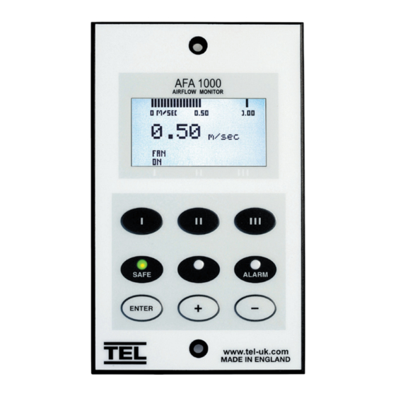
AFA1000/2 MK2 Airflow Monitor Installation & Operating Manual 2 OVERVIEW OF THE AIRFLOW CONTROLLER 2.1 Operator Display Panel Airflow bar graph or Alarm Time Line Velocity display m/sec or fpm or Plain Text “Air Safe / Air Fail” Control Pushbutton Icons... -
Page 11: Display Features
AFA1000/2 MK2 Airflow Monitor Installation & Operating Manual Display Features The Airflow Monitor display has the following features: The digital display is a backlit, full colour high resolution graphic unit with a visual display area of approx 45 x 34mm. The display operates through the software allowing the generation of figures, wording and icons. -
Page 12: Displayed Alarms And Events
AFA1000/2 MK2 Airflow Monitor Installation & Operating Manual Displayed Alarms and Events Sash High will be displayed when the Sash alarm is enabled and the sash is raised above the max safe working opening. Sash High will alternate on/off with the velocity reading. -
Page 13: Additional Alarms And Events
AFA1000/2 MK2 Airflow Monitor Installation & Operating Manual Additional Alarms and Events Mains Fail - will be displayed if the power fails to the monitor (when enabled) *Note – this is an optional extra feature that requires an additional battery unit... -
Page 14: Pushbuttons
AFA1000/2 MK2 Airflow Monitor Installation & Operating Manual Pushbuttons The AFA1000/2 has 3 menu configurable pushbuttons. Each pushbutton can be configured to a different function. The pushbutton Icon and status is shown on the display above the pushbutton. a. Pushbutton 1 Fan On/Off –... -
Page 15: Diagnostics Menu
AFA1000/2 MK2 Airflow Monitor Installation & Operating Manual Diagnostics Menu The AFA1000/2 has a diagnostics menu that shows current Input and Output status, Coms data and also includes an Alarm Test function. To access the diagnostics menu press the ‘+’ and ‘-’ buttons together whilst in the run screen. - Page 16 AFA1000/2 MK2 Airflow Monitor Installation & Operating Manual Input Data:- Input 1 - 0 / Off / On / Not Used Input 2 - 0 / Off / On / Not Used Input 3 - 0 / Off / On / Not Used 0 = Analogue Input e.g.
-
Page 17: External Connections
AFA1000/2 MK2 Airflow Monitor Installation & Operating Manual External Connections The AFA1000/E has the following Inputs:- Input 1 Volt free input configurable for normally closed, normally open relays or Analogue 0-5VDC Input This input can be configured as:- Digital Input Functions (Closed or Open volt free contact):-... - Page 18 AFA1000/2 MK2 Airflow Monitor Installation & Operating Manual Input 3 Volt free input configurable for normally closed, normally open relays or Analogue 0-5VDC Input This input can be configured as:- Digital Input Functions (Closed or Open volt free contact):- Alarm disable...
- Page 19 AFA1000/2 MK2 Airflow Monitor Installation & Operating Manual Optional Inputs Temperature Sensor Bespoke Temperature sensor for connection into inputs 1, 2 or 3 to give temperature display with high and low temperature alarms. PIR Occupancy Sensor Auxiliary PIR used for Close Sash alarm based on Fume Cupboard occupancy.
-
Page 20: Functions And Operation
3. FUNCTIONS & OPERATION... -
Page 21: Airflow Functions
AFA1000/2 MK2 Airflow Monitor Installation & Operating Manual 3 FUNCTIONS & OPERATION 3.1 Airflow Functions The AFA1000/2 airflow display can be set up using the pushbutton menus to display airflow in units of m/sec or fpm and can also be set to show plain text “Air Safe” & “Air Fail” only. -
Page 22: Pushbutton Functions
AFA1000/2 MK2 Airflow Monitor Installation & Operating Manual Pushbutton Functions The AFA1000/2 has 3 programmable pushbuttons. The pushbutton Icon is displayed in the screen above the relevant pushbutton and are identified as Pushbutton I, Pushbutton II, & Pushbutton III Each Pushbutton has a Power Up Memory function that will set the pushbutton function back to the last status following a power fail cycle e.g. - Page 23 AFA1000/2 MK2 Airflow Monitor Installation & Operating Manual Pushbutton II Lights On / Off • Pushbutton II set to Lights On / Off • Lights On /Off Relay operates UV Lights On / Off • Pushbutton II set to UV Lights On / Off • UV Lights On /Off Relay operates Pump On / Off •...
-
Page 24: Input Functions
AFA1000/2 MK2 Airflow Monitor Installation & Operating Manual Input Functions The AFA1000/2 has 3 programmable Inputs that can be set to analogue (0-5VDC), digital open or digital closed operation. Analogue input functions Temperature • Any Input set to Analogue - Temperature •... - Page 25 AFA1000/2 MK2 Airflow Monitor Installation & Operating Manual External alarm • When input configured as External alarm is activated • Red LED on (Flashing) – (if configured) • External Alarm toggles on /off with display -- (if configured) • Audible alarm sounds – can be muted via Enter pushbutton •...
- Page 26 AFA1000/2 MK2 Airflow Monitor Installation & Operating Manual Mains Fail (Optional extra feature) • When the input configured as Mains Fail is activated • Red LED on • Mains Fail is displayed • Audible alarm sounds • Audible can be muted via Enter pushbutton -- this silences the alarm if configured.
-
Page 27: Components
4. COMPONENTS... - Page 28 AFA1000/2 MK2 Airflow Monitor Installation & Operating Manual 4 COMPONENTS 4.1 Airflow Monitor Components 1 – AFA1000/2/MK2 Airflow Monitor 1 – Airflow Sensor c/w 2M RJ45 Sensor Cable 1 – Plug in type low voltage power supply with 5M Cable Version 01 / p.28...
-
Page 29: Auxiliary Components
AFA1000/2 MK2 Airflow Monitor Installation & Operating Manual Auxiliary Components The following auxiliary components are available for the AFA1000/2 airflow monitor:- Sash High Proximity Switch - Used for Sash High Alarm Sash High Micro Switch - Used for Sash High Alarm Personnel Sensor -... -
Page 30: Installation
5. INSTALLATION... -
Page 31: Installation Of Standard Components
AFA1000/2 MK2 Airflow Monitor Installation & Operating Manual 5 INSTALLATION Installation of standard components The following section outlines the installation of the various components of the Airflow monitor system. As the size and format of individual Fume Cupboards varies considerably, specific instructions are not possible, though the principles outlined below should remain valid in all cases. -
Page 32: Typical Installation Diagrams
AFA1000/2 MK2 Airflow Monitor Installation & Operating Manual Typical Installation diagram a. Typical Double wall style Fume Cupboard b. Typical Euro Single Wall style Fume Cupboard Version 01 / p.32... -
Page 33: Dimensions And Cut Out Details
AFA1000/2 MK2 Airflow Monitor Installation & Operating Manual NOT TO SCALE Dimensions and Cut Out details AFA1000/2/MK2 Panel Cut out Dimensions Dimensions SM6 Sensor SM6 Sensor Panel Dimensions Cutout Dimensions (Rear view) (Front View) Version 01 / p.33... -
Page 34: Sm6 Airflow Sensor Installation
AFA1000/2 MK2 Airflow Monitor Installation & Operating Manual 5.4 SM6 Airflow sensor installation It is very important to position the SM6 If possible mount the sensor on the front the front of the fume cupboard and connect of the fume cupboard and use a short length... -
Page 35: Configuration & Calibration
6. CONFIGURATION & CALIBRATION... -
Page 36: Start Up
AFA1000/2 MK2 Airflow Monitor Installation & Operating Manual 6 CONFIGURATION & CALIBRATION 6.1 Configuration The Airflow Monitor can be configured via a Laptop or PC using a variety of ‘set up’ programs each designed for a particular application with a combination of inputs, outputs and push buttons. -
Page 37: Calibration
AFA1000/2 MK2 Airflow Monitor Installation & Operating Manual Calibration Press Enter from the “Requires set up” screen or if the monitor is in the Run screen Press and Hold the Enter button for 5 seconds until the Main Menu is displayed. -
Page 38: Calibration Notes
AFA1000/2 MK2 Airflow Monitor Installation & Operating Manual Calibration Notes When using a standard Fume Cupboard with Vertical Sliding sashes open the sash to the normal max safe working height for the Low Air sample. For the Higher Air sample close the sash to approx 50% of the opening used for the Lower Air sample. -
Page 39: Auxiliary Features And Connections
7. AUXILIARY FEATURES & CONNECTIONS... -
Page 40: Optional Input Function - Temperature Sensor
AFA1000/2 MK2 Airflow Monitor Installation & Operating Manual 7 AUXILIARY FEATURES & CONNECTIONS Optional Input function - Temperature Sensor The AFA1000/2 can be fitted with a temperature sensor to display the fume cupboard temperature and give high and low temperature alarms. The temperature display can be hidden from view or shown alongside the airflow velocity. - Page 41 AFA1000/2 MK2 Airflow Monitor Installation & Operating Manual To Setup the Temperature input using the pushbutton menus:- Press Enter from the “Requires set up” screen or if the monitor is in the Run screen Press and Hold the Enter button for 5 seconds until the Main Menu is displayed.
-
Page 42: Optional Input Function - Close Sash Alarm
AFA1000/2 MK2 Airflow Monitor Installation & Operating Manual Optional Input function - Close Sash Alarm A Close Sash alarm can be set up on the monitor to inform the user that the sash has been left open when the Fume Cupboard is unoccupied. The alarm can be set with a time delay before activation to allow the user to briefly leave and return to the Fume Cupboard and can also be set with a repeat alarm if the sash is left open for prolonged periods of time. - Page 43 AFA1000/2 MK2 Airflow Monitor Installation & Operating Manual The micro switch connections will depend on the switch activation. The output of the PIR is wired in series with the switch so the output should be active (switch contact closed) when the...
-
Page 44: Rs485 Coms Output
8. RS485 COMS OUTPUT... -
Page 45: Overview And Connections
Overview and connections The AFA1000 series has on board RS485 coms with 3 protocols:- Protocol Description Protocol for connection to TEL Configure Manager PC software and room controls Modbus Modbus RTU protocol BACnet BACnet MS/TP protocol (To connect to BACnet IP a 3rd party router is required) -
Page 46: Configuration Settings
Note - when changing Protocols the AFA1000 should be power cycled once re-configured to ensure the changed take effect. The TEL protocol has fixed parameters so cannot be adjusted in the field, to select the TEL protocol using the pushbutton menus:- Press Enter from the “Requires set up”... - Page 47 AFA1000/2 MK2 Airflow Monitor Installation & Operating Manual To Setup the AFA1000 with BACnet protocol using the pushbutton menus:- Press Enter from the “Requires set up” screen or if the monitor is in the Run screen Press and Hold the Enter button for 5 seconds until the Main Menu is displayed.
-
Page 48: Testing And Troubleshooting
AFA1000/2 MK2 Airflow Monitor Installation & Operating Manual Testing and troubleshooting The AFA1000 diagnostics menu can be used to check the coms settings and operation once the AFA1000 coms parameter settings have been set up. From the run screen press the + & - buttons together to access the diagnostics screen. -
Page 49: Config Manager
TEL software package CONFIG MANAGER is available for uploading and downloading parameter configuration files to the AFA1000. The config manager software is Windows based software that runs on a PC or Laptop and requires a RS232/485 converter and TEL coms adaptor to communicate with the RS485 coms port on the AFA1000. - Page 50 AFA1000/2 MK2 Airflow Monitor Installation & Operating Manual Connection Diagram with RS232/485 converter Version 01 / p.50...
-
Page 51: Warranty
9. WARRANTY... - Page 52 AFA1000/2 MK2 Airflow Monitor Installation & Operating Manual 9 WARRANTY Seller warrants that this product, under normal use and service as described in the operator’s manual shall be free from defects in workmanship and material for a period of twelve (12) months, or the length of time specified in the operator’s manual, from the date of shipment to the customer.
- Page 53 Temperature Electronics Ltd. Unit 2, Wren Nest Road, Glossop, SK13 8HB United Kingdom Tel: +44 (0)1457 865635 Fax: +44 (0)1457 868843...
Need help?
Do you have a question about the AFA1000/2 MK2 and is the answer not in the manual?
Questions and answers