Table of Contents
Advertisement
Quick Links
This manual contains text, diagrams and explanations which will guide the reader in the correct
installation, safe use and operation of the FX
read and understood before attempting to install or use the unit. Further information can be found in the
associated manuals list below.
Specifications are subject to change without notice
Guidelines for the Safety of the User and Protection of the
FX
-2AD-BD Analog Input Expansion Board.
1N
This manual has been written to be used by trained and competent personnel. The definition of such a
person or persons is as follows:
a) Any engineer using the product associated with this manual, should be of a competent nature,
trained and qualified to the local and national standards. These engineers should be fully aware of
all aspects of safety with regards to automated equipment.
b) Any commissioning or service engineer must be of a competent nature, trained and qualified to
the local and national standards.
c) All operators of the completed equipment should be trained to use that product in a safe and
coordinated manner in compliance to established safety practices.
Note: The term 'completed equipment' refers to a third party constructed device which contains or uses
the product associated with this manual.
Note's on the Symbols Used in this Manual
At various times through out this manual certain symbols will be used to highlight points of information
which are intended to ensure the users personal safety and protect the integrity of equipment.
1) Indicates that the identified danger WILL cause physical and property damage.
2) Indicates that the identified danger could POSSIBLY cause physical and property
damage.
•
Under no circumstances will Mitsubishi Electric be liable or responsible for any consequential damage
that may arise as a result of the installation or use of this equipment.
•
All examples and diagrams shown in this manual are intended only as an aid to understanding the
text, not to guarantee operation. Mitsubishi Electric will accept no responsibility for actual use of the
product based on these illustrative examples.
•
Owing to the very great variety in possible application of this equipment, you must satisfy yourself as
to its suitability for your specific application.
Associated Manual
Manual Name
FX
Series
1S
Programmable controllers
Hardware Manual
FX
Series
1N
Programmable controllers
Hardware Manual
FX Series of
Programmable controllers
Programming Manual ΙΙ
Indispensable manual
FX
-2AD-BD Analog Input Expansion Board
1N
-2AD-BD Analog Input Expansion Board and should be
1N
Manual
Number
Describes contents related to hardware of the
JY992D83901
FX
1S
and installation.
Describes contents related to hardware of the
JY992D89301
FX
1N
and installation.
Describes instructions in FX
JY992D88101
series.
User's Manual
JY992D96201D
Description
series PLC, such as specifications, wiring
series PLC, such as specifications, wiring
/FX
/FX
/FX
1S
1N
2N
2NC
Advertisement
Table of Contents

Related Manuals for Mitsubishi Electric FX1N-2AD-BD


Summary of Contents for Mitsubishi Electric FX1N-2AD-BD
- Page 1 • All examples and diagrams shown in this manual are intended only as an aid to understanding the text, not to guarantee operation. Mitsubishi Electric will accept no responsibility for actual use of the product based on these illustrative examples.
-
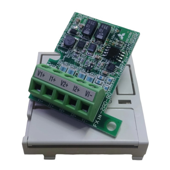
Page 2: External Dimensions And Each Part Name
1. Introduction The FX -2AD-BD analog input expansion board (hereafter called “2AD” or “expansion board”) is to be installed in an FX or FX series PLC, to increase the analog input by 2 points. 1.1 Features of 2AD 1) Analog input of two points can be increased using 2AD. If a 2AD is used, internal mounting in the top of the PLC means that there is no need for a change to the installation area of the PLC. -
Page 3: General Specifications
2. Specifications 2.1 General Specifications Same as the programmable controller main unit. (Refer to the programmable controller main unit manual) 2.2 Power Supply Specifications Power supplied by internal feed of the programmable controller main unit. 2.3 Performance Specifications Table 2.1: Performance Specifications Specification Item Voltage input... -
Page 4: Applicable Cables
4. Wiring Caution: Cut off all phases of power source before installing / removing or performing wiring work on the expansion board in order to avoid electric shock or damage of product. Note: • Do not lay signal cable near to high voltage power cable or house them in the same trunking duct. - Page 5 Table 5.1: Allocation of Device Device Description D8112 Digital value of Ch1 D8113 Digital value of Ch2 5.2 Basic Example Program Note: • Drive M8112 and M8113 which specifies the analog to digital conversion characteristic with M8000 (“a” type contact of the RUN monitor) or M8001 (“b” type contact of the RUN monitor).
- Page 6 • This product is designed for use in industrial applications. Note • Authorized Representative in the European Community: Mitsubishi Electric Europe B.V. Gothaer Str. 8, 40880 Ratingen, Germany Manual number : JY992D96201 Manual revision : D Date : April 2015...
- Page 7 All examples and diagrams shown in this manual are intended only as an aid to understanding the PLC Type Applicable version avoid malfunction. text, not to guarantee operation. Mitsubishi Electric will accept no responsibility for actual use of the series V2.00 or later product based on these illustrative examples.
- Page 8 Authorized Representative in the European Community: The program example based on the equation above is as shown in the figure below. (In Ch1 case) 5. Example Program Mitsubishi Electric Europe B.V. Gothaer Str. 8, 40880 Ratingen, Germany M8001 Analog amount (0 ~ 10V, 4 ~ 20mA) input to each channel is stored in data registers (D8112, D8113) as M8112 digital values.
Need help?
Do you have a question about the FX1N-2AD-BD and is the answer not in the manual?
Questions and answers