Table of Contents
Advertisement
7-DAY PROGRAMMABLE THERMOSTAT
(FOR BOTH CONVENTIONAL AND HEAT PUMP SYSTEMS)
I N S TA L L AT I O N A N D O P E R AT I N G I N S T R U C T I O N S
• Please read all of these instructions carefully before beginning
installation.
• Label every wire terminal designation on your existing thermostat wiring
before removing your old thermostat.
• Ignore the color of the wires since they may not comply with any
standard. Please connect wires using the terminal letter designations.
Thank you for your confidence in our product. To obtain the best results from
your investment, please read and follow the installation procedures carefully, and
one step at a time. This will save you time and minimize the chance of damaging
either the thermostat or possibly your heating and cooling system. These
instructions may contain information beyond that which may be required for your
particular installation.
CAUTIONS AND WARNINGS . . . . . . . . . . 2
SYSTEM COMPATIBILITY . . . . . . . . . . . . 3
FEATURES . . . . . . . . . . . . . . . . . . . . . . . 4
TOOLS YOU MAY NEED . . . . . . . . . . . . . . 4
MOUNTING LOCATION . . . . . . . . . . . . . . 5
REMOVE OLD THERMOSTAT . . . . . . . . . . 5
INSTALL THERMOSTAT BASE . . . . . . . . . 6
WIRING INFORMATION . . . . . . . . . . . . . . 7
WIRING DIAGRAMS . . . . . . . . . . . . . . . . 9
COMPLETE THE INSTALL . . . . . . . . . . . 18
WARNING: Use Energizer
Energizer
DURACELL
© 2014 LUX PRODUCTS CORPORATION. ALL RIGHTS RESERVED
T X 9 1 0 0 U c
SMART TEMP
IMPORTANT!
®
or DURACELL
®
is a registered trademark of Eveready Battery Company, Inc.
®
is a registered trademark of The Procter & Gamble Company
®
UNIVERSAL
FRONT PANEL ITEMS . . . . . . . . . . . . . . 18
SETUP OPTIONS. . . . . . . . . . . . . . . . . . 19
OPERATING INSTRUCTIONS . . . . . . . . . 23
TEMPERATURE PROGRAMS . . . . . . . . . 25
ADVANCED FEATURES . . . . . . . . . . . . . 26
BATTERY REPLACEMENT . . . . . . . . . . . 34
TECHNICAL ASSISTANCE . . . . . . . . . . . 35
LIMITED WARRANTY . . . . . . . . . . . . . . 35
MERCURY NOTICE . . . . . . . . . . . . . . . . 36
®
Alkaline Batteries Only.
52174
Advertisement
Table of Contents

Related Manuals for Lux Products SMART TEMP TX9100Uc


Summary of Contents for Lux Products SMART TEMP TX9100Uc
-
Page 1: Table Of Contents
WARNING: Use Energizer ® or DURACELL ® Alkaline Batteries Only. Energizer ® is a registered trademark of Eveready Battery Company, Inc. ® DURACELL is a registered trademark of The Procter & Gamble Company © 2014 LUX PRODUCTS CORPORATION. ALL RIGHTS RESERVED... -
Page 2: Cautions And Warnings
CAUTIONS AND WARNINGS: • This thermostat requires batteries to operate and failure or sub-standard performance of the batteries may impair or prevent the correct operation of the thermostat. Use Duracell ® or Energizer ® alkaline batteries ONLY for all LUX thermostats requiring batteries. -
Page 3: System Compatibility
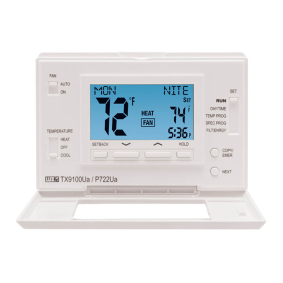
T X 9 10 0 U c LCD Display Screen Fan Mode Set Slide Switch AUTO Switch DAY/TIME TEMP PROG SPEC PROG TEMPERATURE FILT / ENRGY HEAT SETBACK HOLD COPY/ COOL EMER NEXT System Mode Switch UP / DOWN Buttons SYSTEM COMPATIBILITY: The electrical rating for this thermostat is 1.5 Amps per terminal, with a maximum total combined load of 3.0A for all terminals combined. -
Page 4: Features
FEATURES: • 1 or 2-Heat / 1 or 2-Cool, 7-day programming • Universal Compatibility for all system types • Each day of the week can be programmed separately • Exclusive LUX ® Speed Slide for easy programming • User-selectable periods per day (2 or 4) •... -
Page 5: Mounting Location
MOUNTING LOCATION: On replacement installations, mount the new thermostat in place of the old one unless the conditions listed below suggest otherwise. On new installations, please follow these general guidelines: 1. Mount the thermostat on an inside wall, about 5 ft. (1.5m) above the floor. 2. -
Page 6: Install Thermostat Base
INSTALL THERMOSTAT BASE: THERMOSTAT TOP VIEW 1. Strip wire insulation leaving only 3/8 in. (9.5mm) bare wire ends, and clean off any corrosion present. 2. Fill the wall opening with non-combustible insulation to prevent drafts from affecting the thermostat’s normal operation. 3. -
Page 7: Wiring Information
WIRING INFORMATION: CONNECTING THE WIRES: When attaching the wires to the thermostat, please ensure that the bare wire ends are held ALL the way into the terminal block while the screw is being tightened. WIRING BASE PLATE NOTICE: This thermostat model is part of a family of similar models that have the same general visual appearance. - Page 8 WIRING DIAGRAM NOTES: (Important, please read all notes before connecting wires) • If the information provided in the following wiring diagrams does not clearly represent or match your system, please refer to the “TECHNICAL ASSISTANCE” section of this manual, and contact us before removing any of your existing thermostat wiring.
-
Page 9: Wiring Diagrams
WIRING DIAGRAMS: DIAGRAM SYSTEM TYPE / DESCRIPTION PAGE # CONVENTIONAL: HEATING ............10 1-STAGE OR 2-STAGE 2, 3, 4, 5 WIRES CONVENTIONAL: HEATING ............11 3-WIRE ZONE VALVE 3, 4 WIRES CONVENTIONAL: COOLING ............12 1-STAGE OR 2-STAGE 3, 4, 5 WIRES CONVENTIONAL: HEATING AND COOLING ........13 1-STAGE 4, 5 WIRES... -
Page 18: Complete The Install
COMPLETE THE INSTALL: INSTALL BATTERIES INTO THERMOSTAT: Install two brand new Energizer ® DURACELL ® “AA” size alkaline (only) batteries, into the thermostat’s battery compartment. Ensure the batteries are installed in the proper direction. FRONT PANEL ITEMS: These items below are all located behind the door on the front of the thermostat. To open the door, pull outwards using the small indentation in the center of the top edge of the thermostat housing. -
Page 19: System Configuration And Setup Options
UP / DOWN BUTTONS: The UP and DOWN buttons are used to adjust any item that can be changed by the user. Examples are the set temperatures, clock times, and days of the week. In many cases, an item may be flashing if it can currently be adjusted. - Page 20 ITEM #03 (THERMOSTAT TYPE): [PROGRAMMABLE, default] Use this setting for following a daily program routine. [MANUAL] This setting omits the program routine and operates as a manual style non-programmable thermostat. This is very basic and only shows the room temperature and set temperature on the screen, with no clock.
- Page 21 ITEM #08 (DELAY TIME): [5, default] Thermostat waits 5 minutes before turning the system back on after it was last run. This internal delay prevents rapid cycling and provides equipment protection. The 5 minute setting is fine for most applications. [2] Same operation as above but reduced to 2 minutes between state changes.
- Page 22 Cut-In / Cut-Out Stage) 70˚F Set Temperature Swing Setting= #2 (+/- 0.5˚F) Offset ** Setting= 4˚F degrees Stage) ** Cut-In / Cut-Out DEGREES (F) ** = Only applies if a second heat stage is present...
-
Page 23: Operating Instructions
OPERATING INSTRUCTIONS: SET DAY AND TIME: Place the Set Slide Switch into the DAY/TIME position. With the day flashing, press UP or DOWN to set the day of the week. Press NEXT and the clock time will start flashing. Use UP or DOWN to set the time, making sure the AM/PM indication is correct. - Page 24 prevent damage to the heat pump if outside temperatures are below the manufacturer’s recommendations. As every heat pump has different operating characteristics, you should refer to your heat pump literature to determine when to disable the heat pump and run in Emergency Heat mode. LCD DISPLAY BACKLIGHT: The display screen is lighted to assist viewing at nighttime, or in locations with low light levels.
-
Page 25: Temperature Programs
TEMPERATURE PROGRAMS: By default, this thermostat has 4 separate program periods for both Heat and Cool mode, they are: MORN, DAY, EVE, and NITE. Each period ends at the start time of the following period. The heat programs are set in HEAT mode, and the cool programs are set in COOL mode. -
Page 26: Advanced Features
may continue to perform short single presses of the COPY/EMER button to proceed with copying to the remaining days, one after the other (specific days may be skipped by pressing the UP button to advance past them when they are flashing in the “copy to”... - Page 27 TO START A SETBACK: Ensure that the System Mode switch is in either the Heat or Cool position, and that the Set Slider is in the RUN position. Press and hold the SETBACK button for at least 2 seconds. The screen will change and show the words “HOURS LEFT”...
- Page 28 TO SET THE SPECIAL PROGRAM VALUES: Move the Set Slide switch to the SPEC PROG position. The screen will display “S-PROG”. Use the UP/DOWN buttons to adjust the start time for the MORN period, then press the NEXT button to advance.
- Page 29 TO SET THE HEAT LIMIT STOP: Place the System Mode switch in the OFF position, and the Set Slide switch in the RUN position. Press and hold the UP button while sliding the System Mode switch from OFF to HEAT. The words “CODE” and “T–STOP”...
- Page 30 KEYPAD LOCKOUT: You can lock the front panel buttons to prevent unauthorized tampering of your thermostat settings. NOTE: These keypad lock instructions need to be performed in a timely manner, as the thermostat will timeout and automatically exit the keypad lock screens and return to the Normal Run screen after approximately 10 seconds without a button press.
- Page 31 AIR FILTER MONITOR: In most systems that use a blower fan and air ducts, there is an air filter that is either replaceable or requires cleaning. The filter is usually located in the air handler, where the blower fan is. This thermostat feature assists you with keeping track of proper maintenance and/or periodic replacement intervals for your system’s filter.
- Page 32 Usage, and the Total Cumulative Usage. NOTE: For the Total Cumulative Usage, the timer will record up to a maximum of 99 hours and 59 minutes, then the display will change to “HHHH” for hours only, without the colon in the center. Return the Set Slide switch to the RUN position when you are finished.
- Page 33 SOFTWARE RESET: A Software Reset is used to erase ALL heating and cooling temperature programs, and to return all user-adjustable software settings back to their original factory default values. To perform a Software Reset, first ensure that the thermostat’s Keypad Lockout is not enabled and then move the System Mode switch to the OFF position.
-
Page 34: Battery Replacement
BATTERY REPLACEMENT: This thermostat is powered by two “AA” Alkaline batteries. The batteries should be replaced AT LEAST once per year to ensure reliable operation (or sooner if the phrase “LO BATT” appears in the display screen). The batteries are located on the back of the thermostat’s circuit board. -
Page 35: Technical Assistance
TECHNICAL ASSISTANCE: If you have any problems installing or using this thermostat, please carefully and thoroughly review the instruction manual. If you require assistance, please contact our Technical Assistance department at 856-234-8803 during regular business hours between 8:00AM and 4:30PM Eastern Standard Time, Monday through Friday. -
Page 36: Mercury Notice
MERCURY WARNING AND RECYCLING NOTICE: Mercury is considered to be a hazardous material. If this product is replacing a thermostat that contains mercury in a sealed tube, contact your local waste management authority for instructions regarding recycling and proper disposal. It may be unlawful in your state to place it in the trash.
Need help?
Do you have a question about the SMART TEMP TX9100Uc and is the answer not in the manual?
Questions and answers