Table of Contents
Advertisement
PLEASE NOTE THE ANSI A92.2 STANDARD AND THE MANUAL OF RESPONSIBILITIES CONTAINS RECENTLY
UPDATED INFORMATION. DEALERS, OWNERS, USERS, OPERATORS, LESSORS AND LESSEES MUST ADHERE TO
THESE UPDATED STANDARDS.
YOU HAVE READ AND UNDERSTOOD ALL INFORMATION IN BOTH
OPERATOR'S AND SERVICE MANUALS, PROVIDED WITH EACH
VERSALIFT.
AND IS THE SOLE PROPERTY OF TIME MANUFACTURING CO.
CONTENTS ARE NOT TO BE DISCLOSED, COPIED, OR REPRODUCED
IN ANY MANNER WITHOUT THE EXPRESSED, WRITTEN PERMISSION
OF TIME MANUFACTURING CO.
Time Manufacturing Co. 7601 Imperial Drive P.O. Box 20368 Waco, Texas 76702 Phone: 254-399-2100 Fax: 254-751-0775
Time Manufacturing Co. reserves the right to improve the design or change specifications at any time without notice.
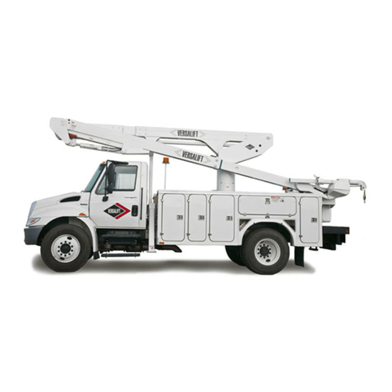
Operator's Manual
VST-36/40/47/52-I
Aerial Device
SERIAL NUMBER
39014-03
MANUAL PART NUMBER
ATTENTION:
DO NOT ATTEMPT TO OPERATE THIS VERSALIFT UNTIL
THIS MANUAL CONTAINS CONFIDENTIAL INFORMATION
06/16
Advertisement
Table of Contents


Need help?
Do you have a question about the VST-36-I and is the answer not in the manual?
Questions and answers