
Related Manuals for ISSI LUMISSIL IS31SE5117


Summary of Contents for ISSI LUMISSIL IS31SE5117
- Page 1 IS31SE5117/IS32SE5117 EVB User Manual IS31SE5117/IS32SE5117 User Manual Revision: A Publication: Sep, 2020 Lumissil Microsystems – www.lumissil.com Rev. A, 09/20/2020...
-
Page 2: Table Of Contents
IS31SE5117 EVB User Manual Table of Contents HARDWARE ENVIRONMENT ............................4 Appearance of Evaluation Board (EVB) ....................... 4 Connection Block Diagram ..........................5 Schematic of Evaluation Board ........................... 6 ORDERING INFORMATION ..........................7 SOFTWARE SUPPORT ..............................8 Software Requirements ............................8 Run GUI Program .............................. - Page 3 IS31SE5117 EVB User Manual 10. Sliders ..................................28 10.1 Slider Type ................................ 28 10.2 Slider Key Calibration (Not yet to finish) ......................28 11. Output Setting ................................. 30 12. I2C Communication ..............................31 12.1 I2C Communication Example1 (Touch Key) ...................... 31 13.
- Page 4 IS31SE5117 EVB User Manual Table of Figures Figure 1: Photo of IS31SE5117 Evaluation Board ....................... 4 Figure 2: Photo of Slider Board and Wheel Board ......................5 Figure 3: IS31SE5117 Evaluation Board connection block diagram ..................5 Figure 4: Schematic of IS31SE5117 Evaluation Board ......................6 Figure 5: Schematic of Slider Board ............................
-
Page 5: Hardware Environment
IS31SE5117 EVB User Manual 1. HARDWARE ENVIRONMENT Appearance of Evaluation Board (EVB) Figure 1: Photo of IS31SE5117 Evaluation Board Lumissil Microsystems – www.lumissil.com Rev. B, 10/25/2020... -
Page 6: Connection Block Diagram
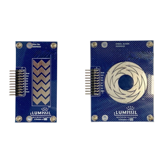
IS31SE5117 EVB User Manual Figure 2: Photo of Slider Board and Wheel Board Connection Block Diagram Figure 3: IS31SE5117 Evaluation Board connection block diagram Lumissil Microsystems – www.lumissil.com Rev. B, 10/25/2020... -
Page 7: Schematic Of Evaluation Board
IS31SE5117 EVB User Manual Schematic of Evaluation Board Figure 4: Schematic of IS31SE5117 Evaluation Board Figure 5: Schematic of Slider Board Lumissil Microsystems – www.lumissil.com Rev. B, 10/25/2020... -
Page 8: Ordering Information
IS31SE5117 EVB User Manual Figure 6: Schematic of Wheel Board ORDERING INFORMATION Part No. Temperature Range Package IS31SE5117-QFLS3-EBGUI -40°C ~ +105°C QFN-24, Lead-free Table 1: Ordering Information For pricing, delivery, and ordering information, please contact LUMISSIL’s marketing and sales team at http://www.lumissil.com/company/office-locations or (408) 969-6600. -
Page 9: Software Support
IS31SE5117 EVB User Manual 2. SOFTWARE SUPPORT Software Requirements Before using the GUI, the PC first needs to install the EzISP USB driver and related files (for example: Microsoft Framework and C++ library). Figure 7: Photo of EzISP Board Note: If there is no ".NET Framework" or the version lower than revision 4.0 on Windows system, ".NET Framework"... - Page 10 IS31SE5117 EVB User Manual Figure 8: Connection of IS31SE5117 evaluation board and EzISP board (1) Execute GUI program (file name: TouchKeyGUI_5117_rls.exe). Lumissil Microsystems – www.lumissil.com Rev. B, 10/25/2020...
-
Page 11: Gui Interface
IS31SE5117 EVB User Manual 3. GUI INTERFACE Connect Status When connecting USB to IS31SE5117 EVB, first, you need to select the correct AD value. If the selected AD value is correct, the Connect Status will be displayed as "Connect" (with a green box), and the following settings can be selected. -
Page 12: Export/Import
IS31SE5117 EVB User Manual Export/Import As shown in Error! Reference source not found. below, "Export Register List" is used to export the register list of IS31SE5117. By exporting the register list, we can save the parameters set by the GUI to the computer. "Import Register List"... - Page 13 IS31SE5117 EVB User Manual Figure 12: GUI write parameters to Flash options Lumissil Microsystems – www.lumissil.com Rev. B, 10/25/2020...
-
Page 14: Io Config
IS31SE5117 EVB User Manual 4. IO CONFIG IO Config Setting When the correct AD value is selected and the Connect Status shows "Connect", it means the EVB has been successfully connected. As shown in the green box in Figure 13, the GUI will identify and display the correct firmware version, software version and chip part number. -
Page 15: Key Variation
IS31SE5117 EVB User Manual 5. KEY VARIATION Operating Mode Switching As shown by the red box in Figure 14, IS31SE5117 EVB is in normal mode, and the corresponding indicator light will turn green. After pressing the "Sleep" button, IS31SE5117 EVB will enter sleep mode, and the corresponding indicator light will turn red. -
Page 16: Value Of Key
IS31SE5117 EVB User Manual The whole interface has prompted box for each programmable parameter. Figure 16: Set the threshold of KEY0 The address of KEY0 THRESHOLD Register is 0x30. KEY0_TH[6:0] are the setting bits of KEY0 THRESHOLD Register (0x30). Threshold range is from 0 to 127. Key will be triggered when the environmental capacitance of touch key is over key threshold. -
Page 17: Key Calibration
IS31SE5117 EVB User Manual Figure 18: Set EN of KEY0 to disable Interrupt enabled setting, as shown in Figure 19 below, Figure 19: KEY's INT and INT_EN Checking in the box is the action of enable interrupt function, no checking means disable. INT_EN should be set to enable first when configure key interrupt for KEY0~KEY15. -
Page 18: Key Value Display
IS31SE5117 EVB User Manual gray. NOISE_TH_SET bit is noise threshold set from 0~127. Input data in the corresponding box and press Enter or Tab key, or move the cursor to another location will set up the threshold. When the VALUE of the sample changes more than NOISE_TH_SET, but not exceeds the key threshold setting, the touch key will be considered to be an ambient noise disturbance. -
Page 19: Setting-1
IS31SE5117 EVB User Manual 6. SETTING-1 As shown in Figure 23 below, the touch key related parameters are set as follows. Figure 23: Setting page of GUI MAX_DURATION_TIME_SET : Maximum Pressing Duration Time Setting As shown in Figure 24 below, Figure 24: MAX_DURATION_TIME_SET option MAX_DUR_ENABLE is the maximum pressing duration time function enable. -
Page 20: Auto_Clear_Int_Set:auto-Clean Interrupt
IS31SE5117 EVB User Manual calibration. Then the touch button can be used after being affected by the water drop. AUTO_CLEAR_INT_SET : Auto-Clean Interrupt As shown in Figure 25 below, Figure 25: AUTO_CLEAR_INT_SET option AUTO_CLEAR_INT_ENABLE is auto-clean interrupt function. Checking is enable. AUTO_CLEAR_INT_TIME is auto-clean interrupt time to choose. -
Page 21: Spread_Spectrum_Set:spread Spectrum Setting
IS31SE5117 EVB User Manual Key Release Key Release Key Press AUTO_CLEAR_INT_ENA BLE=ENABLE If I2C no read 02h, 03h AUTO_CLEAR_INT_TIME Auto_Release INT AUTO_CLEAR_INT_ENA BLE=ENABLE If I2C read 02h, 03h Read 02h, 03h Read 02h, 03h Figure 27: INTB action when AUTO_CLEAR_INT_ENABLE is enabled SPREAD_SPECTRUM_SET :... -
Page 22: Multi-Key_Set:multi-Key Setting
IS31SE5117 EVB User Manual MULTI-KEY_SET : Multi-Key Setting As shown in Figure 29 below, Figure 29: MULTI-KEY_SET option MULTI-KEY_ENABLE is enabled multi-key function. Checking is enable. When MULTI-KEY_ENABLE is not checking, all keys are available. MULTI-KEY_SELECTION can be set to ONE KEY, TWO KEYS or THREE KEYS by clicking the arrow in box. In some applications, such as a password lock, the number of keys pressed need to limit at the same time. -
Page 23: Sample_Average_Set:sampling Frequency And Average Number Setting
IS31SE5117 EVB User Manual Key Release Key Release KEYx Key Press MULTI_PRESS_TIME Key Press INT INT_REPEAT_TIME Key Release INT Figure 31: INTB behavior when setting the INT_REPEAT_SET parameter SAMPLE_AVERAGE_SET : Sampling Frequency and Average Number Setting As shown in Figure 32 below, Figure 32: SAMPLE_AVERAGE_SET option SAMPLE_CNT_SET is to set each button sampling number, the average value of multiple samples is taken as the final key value to improve the scanning stability. -
Page 24: Auto_Sleep_Set:auto Sleep Mode Setting
IS31SE5117 EVB User Manual AUTO_SLEEP_SET : Auto SLEEP Mode Setting As shown in Figure 33 below, Figure 33: AUTO_SLEEP_SET option IS31SE5117 integrates AUTO_SLEEP function and the entering time could be configured. System will enter into SLEEP Mode when no action in touch key. It will be waked up by any key action. In some applications that require low power consumption, it can be set to SLEEP mode automatically. -
Page 25: Scan_Setting:scan And Frequency Setting
IS31SE5117 EVB User Manual KEYx Value Value = 0 NEG_DELTA_TH NEG_DELTA_CNT N__CAL_NEG_TH When negative detect times are over NEG_DELTA_CNT, channel will be When negative value is over calibrated N_CAL_NEG_TH, channel will be calibrated Figure 35: AUTO_SLEEP_SET option SCAN_SETTING : Scan And Frequency Setting Scanning function is set as shown in Figure 36, Figure 36: SCAN_SETTING option REFSEL is VREF selection (Use 1.8V or VDDH as a reference). -
Page 26: Setting-2
IS31SE5117 EVB User Manual 7. SETTING-2 Seven parameters for filter algorithm and one parameter for sleep wake up period are setting as shown in Figure In the SETTIN-2 window, all the SETTING parameters must adjust to evaluation board of IS31SE5117. The customer didn’t be encouraged to adjust these parameters in the SETTIN-2 window. -
Page 27: Setting-Tk3
IS31SE5117 EVB User Manual 8. SETTING-TK3 TK3 stands for Touch Key technology III. It is a name for one of Touch Key technologies in Lumissil. TK3 uses dual-slople technology to design charge charging among an internal charge capacitor, an external reference capacitor and the Touch Key capacitor. -
Page 28: Graph
IS31SE5117 EVB User Manual 9. GRAPH GRAPH is KEY value curves to show the current value of KEY0~KEY15 (Currently IS31SE5117 EVB only supports KEY0~KEY10). As shown in Figure 40, history value of KEYs will be checked by pulling the scroll bar. Users can uncheck the "KEY ENABLE"... -
Page 29: Sliders
IS31SE5117 EVB User Manual 10. Sliders As shown in the blue box in Figure 41, black line is key threshold value, gray line is key value. When the selected key is combined to the slider (Set the slider type through the IO CONFIG page in Figure 13). The keys used as a slider will be updated as the finger moves. - Page 30 IS31SE5117 EVB User Manual Note: If no touch is detected within 3 seconds after pressing the calibration button, the calibration process will end. Figure 43 Slide key calibration Lumissil Microsystems – www.lumissil.com Rev. B, 10/25/2020...
-
Page 31: Output Setting
IS31SE5117 EVB User Manual 11. Output Setting As shown in Figure 44, the customers can organize their own rules according to the hardware layout status. The format of rules are as follows: (1) Select the input Touch Keys. (2) Select the output GPIOs. (3) Select the reaction of the output GPIO to the related input Touch Keys. -
Page 32: I2C Communication
IS31SE5117 EVB User Manual 12. I2C Communication As shown in the blue box in Figure 45, the user can issue I2C commands to the EVB here. On the right, you can choose to load, store, send and clear actions. I2C command set can be composed of several bytes. These bytes can be separated by space or comma. - Page 33 IS31SE5117 EVB User Manual 22:16:45:238 << Read data from register address 07 Note: All the expressed number will be treated as hex, i.e. 16 is 22 in decimal Note: only one bye data can be read Lumissil Microsystems – www.lumissil.com Rev.
-
Page 34: Debug Customer Target Board Based On Gui
IS31SE5117 EVB User Manual 13. Debug Customer Target Board Based On GUI 13.1 Connection Block Diagram As shown in Figure 46 below, the EzISP board can be connected to the customer target board to configure touch keys or LED parameters through the GUI interface. Figure 46: Block diagram of EzISP Board connected to the custom target board As shown in Figure 47 below, the EzISP Board only needs 4 pins to connect to the custom target board, which are VDD, GND, SCL, and SDA. -
Page 35: Revision History
IS31SE5117 EVB User Manual 14. REVISION HISTORY Revision Detail Information Date Initial release. 2020.09.20 Modified I2C communication table. 2020.10.25 Lumissil Microsystems – www.lumissil.com Rev. B, 10/25/2020...
Need help?
Do you have a question about the LUMISSIL IS31SE5117 and is the answer not in the manual?
Questions and answers