Advertisement
18-CHANNEL LED DRIVER EVALUATION BOARD GUIDE
DESCRIPTION
IS31FL3238 is an LED driver with 18 constant current
channels. Each channel can be pulse width modulated
(PWM) by 16 bits for smooth LED brightness control.
In addition, each channel has an 8-bit output current
control register which allows fine tuning the current for
rich RGB color mixing, e.g., a pure white color LED
application. The maximum output current of each
channel is designed to be 76mA, which can be
adjusted
by
one
8-bit
Proprietary programmable algorithms are used in
IS31FL3238 to minimize audible noise caused by the
MLCC decoupling capacitor. All registers can be
programmed via a high speed I2C (1MHz).
FEATURES
2.7V to 5.5V VCC supply
Modulate LED brightness with
256/1024/4096/65536 steps PWM method
Modulate LED DC current with 256 steps method
Global 256 steps analog global current control
PWM frequency selectable
Open short detect function
Spread spectrum
QFN-28 (5mm×5mm) packages
QUICK START
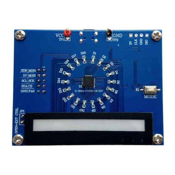
Figure 1: Photo of IS31FL3238
ORDERING INFORMATION
Part No.
IS31FL3238-QFLS4-EB
For pricing, delivery, and ordering information, please contacts ISSI's analog marketing team at
analog@issi.com
or (408) 969-6600.
Integrated Silicon Solution, Inc. – ams.issi.com
Rev. B, 12/28/2018
global
control
register.
-
QWLS4 Evaluation Board
Temperature Range
-40°C to +125°C (Industrial)
Table 1: Ordering Information
RECOMMENDED EQUIPMENT
5.0V, 2A power supply
ABSOLUTE MAXIMUM RATINGS
≤ 5.5V power supply
Caution: Do not exceed the conditions listed above, otherwise
the board will be damaged.
PROCEDURE
The IS31FL3238 evaluation board is fully assembled
and tested. Follow the steps listed below to verify
board operation.
Caution: Do not turn on the power supply until all connections
are completed.
1)
If using external DC power supply connect the
ground terminal of the power supply to the
evaluation board's GND pin and the positive
terminal to the VCC pin. The evaluation board can
also be powered via the Micro USB connector.
2)
Short JP1 to disable external control.
3)
Turn on the power supply/Plug in the Micro USB
and pay attention to the supply current. If the
current exceeds 1A, please check for circuit fault.
4)
Enter the desired mode of display by toggling the
MODE button (K1).
Package
QFN-28, Lead-free
1
Advertisement
Table of Contents

Related Manuals for ISSI IS31FL3238


Summary of Contents for ISSI IS31FL3238
- Page 1 Temperature Range Package IS31FL3238-QFLS4-EB -40°C to +125°C (Industrial) QFN-28, Lead-free Table 1: Ordering Information For pricing, delivery, and ordering information, please contacts ISSI’s analog marketing team at analog@issi.com or (408) 969-6600. Integrated Silicon Solution, Inc. – ams.issi.com Rev. B, 12/28/2018...
-
Page 2: Evaluation Board Operation
A-mixed color. (sketch) from the ISSI website http://ams.issi.com/US/product-analog-fxled-driver.shtml. RGB LEDs (RGB1-RGB6) are breathing effect B. Open JP1. Note: IS31FL3238 solely controls the FxLED function on the evaluation board. Connect the 5 pins from Arduino board to IS31FL3238 EVB: SOFTWARE SUPPORT Arduino 5V pin to IS31FL3238 EVB VCC. - Page 3 OUT13 OUT14 OUT14 OUT16 OUT16 OUT15 OUT15 BIT1 VBlue OUT16 OUT16 OUT17 OUT17 OUT17 100K OUT17 OUT18 TPAD OUT18 BIT2 OUT18 OUT18 IS31FL3238 100K APM4953 LED-RGB-SIDE Figure 3: IS31FL3238 Application Schematic Integrated Silicon Solution, Inc. – ams.issi.com Rev. B, 12/28/2018...
-
Page 4: Bill Of Materials
Capacitor CAP,10µF,16V,±20%,SMD Yageo CC0603MRX5R7BB106 Capacitor C4,C5 CAP, 1µF,16V,±10%,SMD Yageo CC0603KRX7R7BB105 Capacitor CAP,10nF,16V,±10%,SMD Yageo CC0603KPX7R7BB103 Capacitor C7, C8 CAP,33pF,50V,±5%,SMD Yageo CQ0603JRNPO9BN360 Button Button SMD Bill of Materials, refer to Figure 3 above. Integrated Silicon Solution, Inc. – ams.issi.com Rev. B, 12/28/2018... - Page 5 18-CHANNEL LED DRIVER EVALUATION BOARD GUIDE Figure 4: Board Component Placement Guide - Top Layer Figure 5: Board PCB Layout - Top Layer Integrated Silicon Solution, Inc. – ams.issi.com Rev. B, 12/28/2018...
- Page 6 18-CHANNEL LED DRIVER EVALUATION BOARD GUIDE Figure 6: Board Component Placement Guide - Bottom Layer Figure 7: Board PCB Layout - Bottom Layer Copyright © 2018 Integrated Silicon Solution, Inc. All rights reserved. ISSI reserves the right to make changes to this specification and its products at any time without notice. ISSI assumes no liability arising out of the application or use of any information, products or services described herein. Customers are advised to obtain the latest version of this device specification before relying on any published information and before placing orders for products. Integrated Silicon Solution, Inc. does not recommend the use of any of its products in life support applications where the failure or malfunction of the product can reasonably be expected to cause failure of the life support system or to significantly affect its safety or effectiveness. Products are not authorized for use in such applications unless Integrated Silicon Solution, Inc. receives written assurance to its satisfaction, that: a.) the risk of injury or damage has been minimized; b.) the user assume all such risks; and c.) potential liability of Integrated Silicon Solution, Inc is adequately protected under the circumstances Integrated Silicon Solution, Inc. – ams.issi.com Rev. B, 12/28/2018...
-
Page 7: Revision History
18-CHANNEL LED DRIVER EVALUATION BOARD GUIDE REVISION HISTORY Revision Detail Information Data Initial Release 2018.09.17 Update schematic and PCB layout 2018.12.28 Integrated Silicon Solution, Inc. – ams.issi.com Rev. B, 12/28/2018... - Page 8 18-CHANNEL LED DRIVER EVALUATION BOARD GUIDE APPENDIX Ⅰ: IS31FL3238 Arduino Test Code V01A #include<Wire.h> #include<avr/pgmspace.h> #define Addr_GND 0x68 //7 bit format is 0x3F byte PWM_Gamma64[64]= 0x00,0x01,0x02,0x03,0x04,0x05,0x06,0x07, 0x08,0x09,0x0b,0x0d,0x0f,0x11,0x13,0x16, 0x1a,0x1c,0x1d,0x1f,0x22,0x25,0x28,0x2e, 0x34,0x38,0x3c,0x40,0x44,0x48,0x4b,0x4f, 0x55,0x5a,0x5f,0x64,0x69,0x6d,0x72,0x77, 0x7d,0x80,0x88,0x8d,0x94,0x9a,0xa0,0xa7, 0xac,0xb0,0xb9,0xbf,0xc6,0xcb,0xcf,0xd6, 0xe1,0xe9,0xed,0xf1,0xf6,0xfa,0xfe,0xff void setup() { // put your setup code here, to run once: Wire.begin();...
- Page 9 18-CHANNEL LED DRIVER EVALUATION BOARD GUIDE IS_IIC_WriteByte(Addr_GND,i, PWM_Gamma64[j]);//write all PWM set 0x80 IS_IIC_WriteByte(Addr_GND,0x49,0x00);//update PWM & congtrol registers delay(10); //keep 0.5s Integrated Silicon Solution, Inc. – ams.issi.com Rev. B, 12/28/2018...
Need help?
Do you have a question about the IS31FL3238 and is the answer not in the manual?
Questions and answers