Table of Contents
Advertisement
Advertisement
Table of Contents

Subscribe to Our Youtube Channel
Related Manuals for B. Braun Infusomat fmS


Summary of Contents for B. Braun Infusomat fmS
- Page 1 0-10 Infusomat® fmS Service Manual Version 2.3 English...
- Page 2 This Service Manual is valid for Voltage 230 V: Ord. No. Infusomat® fmS, German......871 5424 Infusomat®...
-
Page 3: Table Of Contents
Table of Contents Important Preliminary Remarks Service Work Page 0 - 5 Technical Safety Checks Page 0 - 5 Current Versions Page 0 - 5 Revision Service Page 0 - 5 Quality Management Page 0 - 6 Checks and Repair Page 0 - 6 Notes on ESD... - Page 4 Table of Contents Controller Board Page 4 - 5 Rear Panel Page 4 - 6 Front Frame Page 4 - 11 Pump Unit Page 4 - 12 Pressure Sensor Page 4 - 14 Air Inline Sensor Page 4 - 17 Operating Unit Page 4 - 18...
-
Page 5: Service Work
You will be included in the revision service after: technical training by B. Braun Melsungen or a written order placed with the sales department of B. Braun (fee required). Responsibility of the Manufacturer The manufacturer, person who assembles, installs or imports the... -
Page 6: Quality Management
B. Braun unit. Quality Management B. Braun is certified in accordance with DIN EN ISO 9001 and ISO 13485. This certification also includes maintenance and serv- ice. The unit has the CE label. The CE label confirms that the device corresponds to the “Directive of the Council for Medical Products... -
Page 7: Spare Parts And Test Equipment
Service personnel are responsible for the calibration of their test equipment. Original test equipment can be calibrated at the works of B. Braun. Further information is available upon request. Setting Off Additional notes and warnings are set off as follows:... -
Page 8: List Of Abbreviations
Important Preliminary Remarks List of Abbreviations Abbreviations which are not generally known, but are used in this manual, are listed below. Computer Controlled Clear Digit Electrostatic Discharge Unit Alarm Function Microprocessor Control Microprocessor Liquid Crystal Display Original Infusomat Line Patient Controlled Analgesia Technical Safety Check TEMP... -
Page 9: Technical Training
Entry for Technical Training Application for a technical training course must be made via the responsible representative. Ordering of Spare Parts and Test Equipment Please contact your local B. Braun subsidary. International Technicians (Intercompany) Nadja Machal Fax: +49 5661 / 75 -47 89 e-mail: nadja.machal@bbraun.com... - Page 10 Contact Persons For your notes: 0 - 10 Infusomat® fmS 2.3 gb...
-
Page 11: Physical Construction
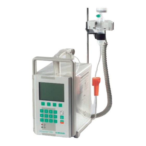
1 - 12 System Overview Physical Construction The Infusomat® fmS is a compact volumetric peristaltic infusion pump. Standard delivery rate range 0.1 to 999.9 ml/h The unit is operated via a membrane keyboard. It is equipped with an LCD-display (liquid crystal display) for the display of the deliv- ery rate and the operating support of the user. - Page 12 System Overview Infusion Lines The Infusomat® fmS can be operated with the Original Infuso- mat® Line (OIL) and the Infusomat® Space Line. The lines are dis- tinguished by the different silicone pump segments. They have to be inserted in a different way; in addition the TSC differs. WARNING OPERATING THE UNIT ALTERNATELY WITH THE ORIGINAL INFU- SOMAT®...
-
Page 13: Operation Flow Chart
System Overview Operation Flow Chart Switch On Service connector Standard operation Special functions ... plugged ... Dose calculation Bolus function Standby function Set delivery rate Volume preselection Time preselection Drug change CC Mode Switch-off pres- sure Rate calculation Drop control Piggyback Start infusion Battery capacity... -
Page 14: Function
System Overview Function Two independent software-controlled microprocessor systems control and monitor the hardware. On the basis of their functions, they are defined respectively as a control and a function proces- sor. Both systems work with independent clock frequencies and have access to different program and data memories. All safety- relevant functions are handled by both microprocessors and the results are counter checked (CF- and FC-latch). -
Page 15: Voltage Supply
System Overview Voltage Supply The voltage supply is generated either directly from mains, via the FM connector (14 V connection to the fluid manager system), or via the MFC-connector (11 to 16 V) and as an internal supply via the internal 7.2 V NiCD battery. The mains module is available in three versions: 230 V, 220 / 230 / 240 V and 100 / 110 / 120 V. -
Page 16: Signal Table
System Overview Fig.: 1 - 4 Signal Table Signal Meaning Signal Meaning Voltage supply electronic PKS2 Pump Head Sensor 2 5V-HT Overvoltage test PKSS Pump Head Sensor Control 5V-LT Undervoltage Test Staff Call Relay Control AK-I Battery Charge and Discharge Current PRS-F Staff Call Relay Function Channel AK-LAD... -
Page 17: Mains Operation
System Overview Signal Meaning Signal Meaning Electronic Occlusion Pressure TD-A0 Text Display Address 0 FMC-F FM Connection Function Channel TD-A1 Text Display Address 1 FMC-K FM Connection Control Channel TD-A2 Text Display Address 2 UEXT-N External 12V Supply (-) TD-A3 Text Display Address 3 UEXT-P External 12V Supply (+) -
Page 18: Battery Operation
System Overview In mains operation battery function is checked during the switch- on test. Therefor the charge and discharge current are measured and the charging of the battery is interrupted for the duration of measurement. Battery Operation The battery function is monitored by the following data: charge current, discharge current and time, and self-discharge time. -
Page 19: Computer Interface
The Infusomat® fmS is equipped with a computer interface. It can be connected to the optical interface or via the MFC service con- nector. To activate the computer operation please ask for a de- tailed description from B. Braun. Up to software version IFMC: DIANET Star From software version IFMe, IFME on: Dianet Infusomat®... -
Page 20: Braun Fluid Manager System (Fm System)
Braun fluid manager system (fm system) The Infusomat® fmS can be operated as a stand-alone unit or in- tegrated in an intensive care unit, e.g. the B. Braun fluid manager system (fm system). It is integrated by simply snapping the unit into the system. -
Page 21: Accessories
System Overview Accessories General Designation Ord. No. Mounting clip for drop chamber ”TK 2000” ..3477 3223 Mounting clip for drop chamber ”Intrafix air” ..3477 3215 Drop sensor, complete ......3450 578A Short pole clamp . - Page 22 System Overview For your notes: 1 - 12 Infusomat® fmS 2.3 gb...
-
Page 23: Software Update
All units used in one ward should have the same software status and basic setup to avoid operator mistakes. Note Software updates must be reported to B. Braun for registration. Observe the notes of the update program and the supplements! Infusomat® fmS 2.3 gb... -
Page 24: Approved Software Versions
Software Approved Software Versions IFMC02001 Basic software (Must not be used any more. Please contact the Technical Service of B. Braun). IFMC02002 Error elimination at Bolus special function at staff call on the fm system Optimized air sensor evaluation IFMC02003... - Page 25 Software IFMe02005 / IFME03005 Cyclical battery test Retaining or deleting last dose calculation when unit is switched off, can be set in the Service Program IFMe02006 / IFME03006 Optimized switch-off cycle of Service Program IFMe02007 / IFME03007 Reset the battery capacity from 0 mAh to 1 mAH in the event of a negative battery test result.
-
Page 26: Error Messages And Alarms
Software Error Messages and Alarms Alarms of the function processor 80c535 are displayed in the text box of the LCD-display. Alarms of the control processor 68HC11 7 segment display are displayed in the 7 segment display. The alarms help to trou- bleshoot unit malfunctions. - Page 27 Software Control Microprocessor 68hc11 FFxx is displayed in the 7 segment display with flashing dots. FFxx is the error code. 7 Segment Display Description FF01 dummy for test FF02 battery not present / missing battery current FF03 defective RAM memory FF04 defective program memory FF05...
-
Page 28: Software Default Values
Software Software Default Values Unit No.: _______________________ Menu Item Default Customer Setting Standard function User language depending on Art. No. _______________________ Alarm type single stage _______________________ Staff call static without OFF Alarm, without _______________________ switch-on pulse Ward identification ”Ward Identification” _______________________ Drug 0 blank... - Page 29 Software Menu Item Default Customer Setting Bolus key _______________________ Bolus rate 999.9 ml/h _______________________ Calibration data Air sensor calibration value 182 mV must not be changed Scale factor _______________________ Unit specific data DIANET type no. depending on unit _______________________ Unit No. depending on unit _______________________ Operating hours...
- Page 30 Software For your notes: 2 - 8 Infusomat® fmS 2.3 gb...
-
Page 31: Structure Of The Service Program
3 - 10 Service Program Structure of the Service Program Service connector plugged Switch On Short display: software version, user language Standard operation Special function (see operating (see operating flow diagram) flow diagram) Service Program activated Group: Group: Group: Group: Group: Unit data History data... -
Page 32: Additional Functions With
Service Program Additional Functions with Software Version and User Language Plugged Service Connector 1. Plug service connector on MFC socket at the rear of the unit. 2. Switch on unit and keep the ON/OFF button pressed (for max. 15 s). 3. -
Page 33: Start / Quit The Service Program
Service Program Start / Quit the Service Program Activate the Service Program 1. Plug service connector on MFC socket at the rear of the unit. - ** appears in the display. 2. Select ”Service Program” with the SM key. When the service program is activated the red alarm LED flashes. -
Page 34: History Data
Service Program Drug Name Function 110.0 Memory for maximum 10 drugs and 20 characters per name. 1. Display stored drug names with NEXT key. 2. Delete displayed entry with CLR. 3. Press YES to modify a drug name: Move cursor to character with NEXT. Select new character from line 3 with <<... -
Page 35: Test
Service Program 2. Return to initial function with END. Pump Head Cycles Function 220.0 Display of the pump head cycles (delivered volume). 1. OK activates the display. 2. Return to initial function with END. Operating Alarms Function 230.0 15 14 13 12 11 10 9 8 7 6 5 4 3 2 1 0 The last 20 operating alarms can be recalled. -
Page 36: Unit Modifications
Service Program Pressure Sensor Function 310.0 Test Equipment Calibration gauge 4 mm (see „Test Equipment and Special Tools“ ➪ p. 9 - 1) 1. Push in the bottom slide of the finger pump. 2. Activate function with OK button. 3. Open unit door. 4. - Page 37 Service Program The activation of the "10 minutes off” alarm is only permissible, if: the staff call is connected and the Infusomat® fmS has an attention label (label drawing no. M007100000F04). 1. OK activates the function. 2. Select alarm tone with NEXT. 3.
- Page 38 Service Program Menu Function 450.0 The availability of menus on the user interface can be set. Double rate entry Online rate entry Interval Bolus 1. OK activates the function. 2. Activate / deactivate the decimal function with NEXT. 3. Acknowledge with YES. 4.
-
Page 39: Calibration
Service Program Dianet Mode Display Function 480.0 When operated with DianetStar the respective DianetStar-mode (CA, CC, CD) with address 01, e.g. mode CA and address 01 is dis- played by: „###CA01###“. The duration of the display after the last data transmission can be set between 0 and 255 seconds. - Page 40 Service Program Air Inline Sensor Function 520.0 Alignment or check of the air inline sensor value (alarm threshold) (see „Air Inline Sensor“ ➪ p. 4 - 17). 1. OK activates the function. 2. Press OK again to activate the air inline sensor value. 3.
-
Page 41: Mains Fuses
6. Charge battery (16 h). Fig.: 4 - 1 Note Defective batteries must be orderly disposed of, e.g. send back to B. Braun Melsungen AG, Wareneingang. Check Perform switch-on test in battery operation and check the battery running time, if necessary. -
Page 42: Door Lock
Unit Elements Door Lock Designation Ord. No. Door lock complete with push button ... . . 3450 5601 Spring holder for door lock ..... . 3450 5440 Mounting for door lock . -
Page 43: Pump Cover
Unit Elements Pump Cover Designation Ord. No. Pump cover with lock ......3450 5717 Blind plug 7.1 mm (10 pcs.) ..... 3477 3207 Hinge pin for Torsion spring in lever / pump cover (5 pcs.) . -
Page 44: Housing And Handle
Unit Elements Housing and Handle Designation Ord. No. Housing labelling German ........3450 1843 French . -
Page 45: Controller Board
Unit Elements Controller Board Designation Ord. No. Distance sleeve ....... 3450 3366 Cable outlet motor Air inline sensor connector Buzzer . -
Page 46: Rear Panel
Unit Elements 6. Assembly is done in reverse order. Be careful with the optical components. Insert board in the lower guide parallel to the base plate. (Otherwise problems with the optical interface can occur.) Note If ”Calibration Defective” is displayed after having exchanged the controller board, check whether the correct board (risk of mix-up) was assembled. - Page 47 Unit Elements Signal Name Function Pin 1 Uext- Input of external supply voltage, connection of shield Pin 2 not assigned Pin 3 GND Reference level 0V Pin 4 Staff call Output open collector or standard 74HC level each with 220 -series resistance Pin 5 Ub Output supply voltage...
- Page 48 Unit Elements Exchange Rear Panel (see „Battery“ ➪ p. 4 - 1. Remove battery (see „Housing and Handle“ ➪ p. 4 - 2. Dismount cover 3. Pull off rear panel connectors and loosen both screws on the unit bottom. Rear panel M4x8 Fig.: 4 - 8 4 - 8...
- Page 49 Unit Elements Exchange MFC Connector Board Tools: Special socket spanner M18 1. Remove nuts at the fm recessed plug (red/blue). 2. Pull off connector to the mains power supply and drop sensor, Fig.: 4 - 3. Loosen MFC socket with special socket spanner M18. 4.
- Page 50 Unit Elements Exchange Mains Module Power supply 1. Loosen 3 screws and remove the power supply unit. Note The voltage selection for switchable power supplies is at the fuse element. Exchange Drop Sensor Socket 1. Loosen nut and exchange drop sensor socket. 2.
-
Page 51: Front Frame
Unit Elements Front Frame Designation Ord. No. Front frame without flow inhibitor and pressure spring . . . 3450 5822 Snap-in pin (rear side) Circular seal 571 mm / 45 mm ....3477 3126 Flow inhibitor with pressure spring . -
Page 52: Pump Unit
Unit Elements Pump Unit Designation Ord. No. Finger pump (without motor) including pump, ..3450 1738 pump cover, seal membrane and boards Finger pump (without motor and board) ... 3450 9038 incl. - Page 53 Unit Elements Air alarm: air bubbles in ml and air rate in ml/h respectively User language Special functions (ON/OFF) Menu Staff call type Note If data is not entered, ”Calibration data faulty” may be displayed after the unit is switched on again. 9.
-
Page 54: 4.10 Pressure Sensor
Unit Elements 4.10 Pressure Sensor Test Equipment Ord. No. Pressure calibration device ..... . 0770 5018 Calibration gauge 4 mm (for adjustment after ..0770 1489 exchange of the pump cover) Designation Ord. - Page 55 Unit Elements c) Push pressure sensor with pressure sensor board to the rear until stopper. d) Move lower slide of the finger pump rearwards. e) Note down pressure sensor value. Insert 4 mm calibration gauge. g) Push pressure sensor with pressure sensor board slightly forward.
- Page 56 Unit Elements Remove weight and holder and do not save data. Call in calibration of pressure stage (function 540) in the Service Program. k) Enter the calibration values via the keyboard and ac- knowledge with ”yes”. Quit Service Program and save data. m) Register the changed pressure values in the unit book.
-
Page 57: Air Inline Sensor
Unit Elements 4.11 Air Inline Sensor Designation Ord. No. Air inline sensor incl. connector ....3450 193A Exchange (see „Battery“ ➪ p. 4 - 1. -
Page 58: 4.12 Operating Unit
Unit Elements 4.12 Operating Unit Designation Ord. No. Membrane keyboard with support plate and seal ..3450 1797 Support plate LCD module ........3450 1819 Zero insertion force connector Frame incl. -
Page 59: 4.13 Barcode Label
Unit Elements 4.13 Barcode Label Designation Ord. No. Barcode label ....... . . 3450 9070 Exchange 1. - Page 60 Unit Elements For your notes: 4 - 20 Infusomat® fmS 2.3 gb...
-
Page 61: Visual Inspection
5 - 2 Checks after Repair Depending on the work carried out, perform the relevant check blocks (1., 2. and / or 3.). 1. Visual Inspection 2. Electrical Safety 3. Functional Inspection according to IEC / EN 60601-1 or VDE 0750 and VDE 0751 ❒... - Page 62 Checks after Repair 1. Visual Inspection 2. Electrical Safety 3. Functional Inspection according to IEC / EN 60601-1 or VDE 0750 and VDE 0751 Pressure limitation, mechanical (Reference values measured with electronic pressure sensor) ❒ With original Infusomat® line ❒ P ❒...
- Page 63 6 - 2 Maintenance It is recommended every 2 years. In addition to the technical safe- ty inspection, the following assemblies/components are to be checked: 1. Check rubber feet and if necessary exchange. 2. Check easy running of the pump cover, lock mechanism and door.
- Page 64 Maintenance For your notes: 6 - 2 Infusomat® fmS 2.3 gb...
-
Page 65: Functional Inspection
Checklist for Technical Safety Check – Every 24 Months Unit: Infusomat® fmS User Manufacturer: B. Braun Melsungen AG Observe the Service Manual and the instructions for use. All measured values are to be documented. Accessories used should be included in testing. Make exclusive use of calibrated measuring equip- ment. - Page 66 Technical Safety Check TSC Index d (Master – to be added to the documentation) Visual Inspection Electrical Safety Functional Inspection according to IEC / EN 60601-1 or VDE 0750 and VDE 0751 Pressure cut-off, electronic (Reference values measured with electronic pressure sensor) Delivery rate: 50 ml/h Volume: 250 ml Test without drop sensor...
- Page 67 Technical Safety Check TSC Index d (Master – to be added to the documentation) Visual Inspection Electrical Safety Functional Inspection according to IEC / EN 60601-1 or VDE 0750 and VDE 0751 Delivery accuracy Ambient temperature 20 ... 25 °C Delivery rate: 250 ml/h Measured volume: 25 ml ❒...
- Page 68 Technical Safety Check TSC Index d (Master – to be added to the documentation) Lines Used Accessories Used Calibrated for usage of: ❒ Original Infusomat line (OIL) ❒ MFC staff call line ❒ Original Infusomat Line (OIL) ❒ Infusomat® Space Line ❒...
- Page 69 8 - 8 Procedural Instructions on the TSC Visual Inspection 1. Check the Infusomat® fmS and accessories for cleanliness. 2. Check the Infusomat® fmS and accessories for completeness and check configuration. Pay special attention to the follow- ing parts: a) Check the special additional labels of the Infusomat® fmS adjusted for the Infusomat®...
- Page 70 Procedural Instructions on the TSC Electrical Safety The values to be measured are specified in the TSC (see „Techni- cal Safety Check TSC“ ➪ p. 7 - according to IEC / EN 60601-1 1). The measured values are to or VDE 0750 and VDE 0751 be recorded.
- Page 71 Procedural Instructions on the TSC Functional Inspection Switch on Unit 1. Switch on unit and check the following details: Self-test Audible alarm One short and afterwards two short tones Status displays LEDs (red, green) light up for a short moment LCD lighting Display on the LC display All symbols and display pixels flash for a short moment...
- Page 72 Procedural Instructions on the TSC Test Setup Perform test setup with the subassemblies listed below, please see also Fig.: 8 - An electronic manometer should be used for the measurement described hereafter. If a mechanic manometer is used instead values which are approx. 100 mbar lower are to be expected.
- Page 73 Procedural Instructions on the TSC Pressure Cut-Off, Electronic The MFC service connector must not be plugged. The drop sensor must not be connected. 1. Insert the line of the test setup in the device. 2. Enter a delivery rate according to the TSC. 3.
- Page 74 Procedural Instructions on the TSC 2. Document value. 3. Pull off the MFC service connector. WARNING SWITCH THE DEVICE OFF AFTER THE SAFETY CLAMP WAS CHECKED SO THAT THE ELECTRONIC PRESSURE CONTROL IS RE- ACTIVATED AFTER A RESTART. 4. Switch device off. Delivery Accuracy Requirements: Mount test setup as shown in...
- Page 75 Procedural Instructions on the TSC The accuracy of the delivery rate can be checked using a normal infusion line when the TSC is carried out. A test infusion line (OIL test infusion line with an Infusomat® fmS adjusted for the Original Infusomat® line, and a Space calibration line with an Infusomat®...
- Page 76 Procedural Instructions on the TSC 13. Compare value with the threshold value specifications of the TSC. Battery Check 1. Disconnect the device from the mains supply during opera- tion. 2. The symbol for the mains plug on the LC display goes off. An error message is not triggered and operation of the unit is continued.
- Page 77 9 - 2 Test Equipment and Special Tools For Repair / for TSC Order No. Test equipment case Infusomat fm (complete) ..0770 1527 with: Calibration gauge 4 mm (for adjustment after exchange of the pump cover) ......0770 1489 Pin punch 1.8 mm x 160 mm (for hinge pin/ disassembly of the pump cover) .
- Page 78 Test Equipment and Special Tools For your notes: 9 - 2 Infusomat® fmS 2.3 gb...
-
Page 79: Unit Elements
10 - 4 Spare Parts List 10 - Unit Elements Designation Order - No. Designation Order - No. Battery Rear Panel Battery incl. connector plug Rear panel with screws (M3) and seal ... . . 3450 1860 1.2 Ah / 7.2 V and holder . -
Page 80: Colours
Spare Parts List Designation Order - No. Designation Order - No. Pump Unit Frame with Seal Finger pump (without motor) including pump, ..3450 1738 Seal plate between frame and front panel pump cover, seal membrane and boards (exchange not recommended) . - Page 81 Spare Parts List Designation Order - No. Designation Order - No. Poleclamp Universal Clamp Pole clamp (universal clamp, rotating) ... . 3450 9054 Universal Clamp (Poleclamp) Fig.: 10 - 2 Universal Clamp Universal clamp, complete .
- Page 82 Spare Parts List For your notes: 10 - 4 Infusomat® fmS 2.3 gb...
- Page 83 11 - 2 Index 11 - Maintenance ........6 - 1 Accessories .
- Page 84 Index 11 - 2 Infusomat® fmS 2.3 gb...
-
Page 85: Current Information
Version 2.1 New TSI list New controller board New software Version 2.2 This version was approved by B. Braun on 19.04.2006. The most important changes of this version are listed below: New software New Service Program functions New spare parts Changed occlusion pressure data Version 2.3... - Page 86 Revision Documentation For your notes: A - 2 Infusomat® fmS 2.3 gb...
Need help?
Do you have a question about the Infusomat fmS and is the answer not in the manual?
Questions and answers