Table of Contents
Advertisement
Quick Links
Beginning Serial Number:
CP7531680
Boiler Manual
DO NOT USE BOILER DURING CONSTRUCTION
the requirements given on page 9. Failure to comply could result in severe personal injury, death or substantial property
damage.
This manual must only be used by a qualified heating installer/service technician.
read all instructions, including this manual, and any related supplements. Perform steps in the order
given. Failure to comply could result in severe personal injury, death or substantial property damage.
*
*
Blower cover on sizes CGi 25-5 only
Series 3
Gas-Fired Water Boilers
• Installation
• Startup
unless you provide dust-free air to the boiler area or follow
• Maintenance
• Parts
Before installing
Part Number 550-142-902/1016
,
Advertisement
Table of Contents

Related Manuals for Weil-McLain CP7531680


Summary of Contents for Weil-McLain CP7531680
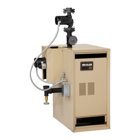
- Page 1 Beginning Serial Number: CP7531680 Series 3 Gas-Fired Water Boilers Boiler Manual • Installation • Maintenance • Startup • Parts Blower cover on sizes CGi 25-5 only DO NOT USE BOILER DURING CONSTRUCTION unless you provide dust-free air to the boiler area or follow the requirements given on page 9.
- Page 2 Boiler Manual GAS-FIRED WATER BOILER — SERIES 3 — How it works . . . ① Control module The control module responds to signals from the room thermostat, air pressure switch and boiler limit circuit to operate the boiler circulator, pilot burner, gas valve and inducer. When room thermostat calls for heat, the control module starts the system circulator and inducer.
- Page 3 Boiler Manual GAS-FIRED WATER BOILER — SERIES 3 — Gas-Fired Induced-Draft Water Boiler Part Number 550-142-902/1016...
-
Page 4: Table Of Contents
Boiler Manual GAS-FIRED WATER BOILER — SERIES 3 — Contents How it works ............ 2 Hazard definitions ..........4 Please read before proceeding ......5 Prepare boiler location ........6–11 Prepare boiler ..........12–13 Venting ............14-19 Water piping ..........20-29 Gas piping ............ -
Page 5: Please Read Before Proceeding
Boiler Manual GAS-FIRED WATER BOILER — SERIES 3 — Please read before proceeding Installer User Read all instructions before installing . Fol- This manual is for use only by your qualified heating • low all instructions in proper order to prevent installer/service technician. - Page 6 Boiler Manual GAS-FIRED WATER BOILER — SERIES 3 — Prepare boiler location — codes & checklist Installations must follow these codes: • Local, state, provincial, and national codes, laws, regulations and ordinances. • National Fuel Gas Code, ANSI Z223.1/NFPA 54 –– latest edition. •...
-
Page 7: Prepare Boiler Location
Boiler Manual GAS-FIRED WATER BOILER — SERIES 3 — Prepare boiler location — clearances Recommended SERVICE clearances Figure 1b Required MINIMUM clearances (Fig. 1a) 1. Provide clearances for cleaning and servicing the boiler and for access to controls and components. See Figure 1a for recommen- dations. -
Page 8: Prepare Boiler
Boiler Manual GAS-FIRED WATER BOILER — SERIES 3 — Prepare boiler location — vent system Failure to follow all instructions can result in flue gas spillage and carbon monoxide emissions, causing severe personal injury or death. Inspect existing chimney before installing boiler. Failure to clean or replace perforated pipe or tile lining will cause severe personal injury or death. - Page 9 Boiler Manual GAS-FIRED WATER BOILER — SERIES 3 — Prepare boiler location — air contamination Table 1 Please review the following information on potential Refer to for products and areas which may cause combustion air contamination problems. contaminated combustion air. To prevent potential of severe personal injury or death, check for products or areas listed below before installing boiler.
- Page 10 Boiler Manual GAS-FIRED WATER BOILER — SERIES 3 — Prepare boiler location — air openings Figure 2 Air openings to interior spaces Combustion air opening location and sizing requirements depend on the clearances around ✷ the boiler. Check the boiler placement compared to Figure 1a, page 7.
- Page 11 Boiler Manual GAS-FIRED WATER BOILER — SERIES 3 — Prepare boiler location — air openings Unusually tight construction FREE AREA of openings — the minimum areas given in this manual are free area (equals the area, Unusually tight construction means (per ANSI Z223.1/ length times width of opening, after deduction for NFPA 54) buildings in which: louver obstruction).
- Page 12 2,000-4,500 Canada CGi-25 2.30 mm CGi-3 and CGi-5 2.55 mm 1.60 mm 1.45 mm CGi-4, CGi-6 - CGi-8 2.70 mm 1.65 mm Note 1: For elevations above 2,000 feet, contact your local Weil-McLain sales office for details. Part Number 550-142-902/1016...
- Page 13 Boiler Manual GAS-FIRED WATER BOILER — SERIES 3 — Prepare boiler — pressure test Hydrostatic pressure test 5. Slowly reopen boiler drain valve until test pressure on the pressure/temperature gauge reaches no more Pressure test boiler before attaching water or gas piping than: (except as noted below) or electrical supply.
-
Page 14: Venting
Boiler Manual GAS-FIRED WATER BOILER — SERIES 3 — Venting — general information CGi venting methods — Chimney draft or Direct exhaust Chimney draft venting Direct exhaust — vertical or sidewall Direct exhaust venting uses inside combustion air with Chimney draft venting uses the natural draft provided no combustion air connector piping. - Page 15 Boiler Manual GAS-FIRED WATER BOILER — SERIES 3 — Venting — Direct exhaust — components Obtain vent system components Table 4 Maximum vent length 1. The following special gas vent systems comply with UL‑1738 and ULC‑S636 standards and are certified by CSA as the only Max.
- Page 16 Boiler Manual GAS-FIRED WATER BOILER — SERIES 3 — Venting — direct exhaust — vent starter 1. Select a vent pipe manufacturer and obtain all vent 3. Follow all applicable national, state, local or provin- components needed, based on boiler location and cial codes when venting the CGi boiler.
- Page 17 Boiler Manual GAS-FIRED WATER BOILER — SERIES 3 — Venting — direct exhaust — termination The vent termination must be located to meet all requirements below (also applies to vertical vent terminations). The minimum distance from adjacent public walkways, adjacent buildings, openable windows and building in the National Fuel Gas Code, ANSI Z223.1/NFPA 54 and/or the Natural Gas and Propane Installation Code, CAN/CSA B149.1.
- Page 18 Boiler Manual GAS-FIRED WATER BOILER — SERIES 3 — Venting — direct exhaust — installation 1. Do not mix types or manufacturers of vent materi- Figure 13 Direct exhaust vertical venting als. 2. Clean all joints before sealing. See vent manufac- turer’s instructions for cleaning and sealing joints.
- Page 19 Boiler Manual GAS-FIRED WATER BOILER — SERIES 3 — Venting — direct exhaust — installation (cont.) Using any termination other than one of those shown Figure 15 Sidewall termination could cause nuisance outages and loss of heat, resulting in substantial property damage. Part Number 550-142-902/1016...
-
Page 20: Water Piping
Boiler Manual GAS-FIRED WATER BOILER — SERIES 3 — Water piping — general information General piping information Circulator If installation is to comply with ASME or Canadian requirements, an ad- The circulator is shipped loose (wiring pre-attached to high temperature limit ditional maybe needed. - Page 21 Boiler Manual GAS-FIRED WATER BOILER — SERIES 3 — Water piping — single-zone system Undersized expansion tanks cause system water to be lost from relief valve and makeup water to be added through fill valve. Eventual section failure can result. Diaphragm-type or bladder- Closed-type expansion tank type expansion tank...
- Page 22 Boiler Manual GAS-FIRED WATER BOILER — SERIES 3 — Water piping — multiple zones Piping multiple zones Piping for radiant heating systems or converted gravity Follow instructions on pages 20 and 21 to install near- systems Piping for boiler or single‑zone piping. (Also refer to radiant heating systems or converted gravity sys- tems , below, if applicable.)
- Page 23 Boiler Manual GAS-FIRED WATER BOILER — SERIES 3 — Water piping — multiple zones (continued) Figure 18 Zoning with circulators Figure 19 Zoning with zone valves — return water 130°F or higher. — return water 130°F or higher. Boiler isolation (balancing) valves Automatic air vent (with diaphragm‑type expansion tank), or con- nect to tank fitting (closed-type expansion tank).
- Page 24 Boiler Manual GAS-FIRED WATER BOILER — SERIES 3 — Piping — low temperature systems Primary/secondary the water temperature being supplied to the radiant (preferred) tubing. bypass piping method required Gauge on all systems to assure the return Primary/secondary bypass piping is preferred because water temperature is accurately set for a minimum of the flow rate and temperature drop in the heating 130°F.
- Page 25 Boiler Manual GAS-FIRED WATER BOILER — SERIES 3 — Piping — low temperature systems (continued) Figure 20 Primary/secondary piping Figure 21 Primary/secondary piping Zoning with circulators Zoning with zone valves Boiler isolation (balancing) valves Relief valve Automatic air vent (with diaphragm‑type expansion tank), or Flow/check valve DO NOT connect to tank fitting (closed-type expansion tank).
- Page 26 Boiler Manual GAS-FIRED WATER BOILER — SERIES 3 — Piping — low temperature systems (continued) BOILER-bypass piping justed using cold (or room temperature) return water to the boiler. (When setting the valves without gauge method installed — using cold or room temperature water —...
- Page 27 Boiler Manual GAS-FIRED WATER BOILER — SERIES 3 — Piping — low temperature systems (continued) Figure 22 Boiler-bypass piping — Zoning with Figure 23 Boiler-bypass piping — Zoning with circulators — (Alternative to primary/ zone valves — (Alternative to primary/ secondary piping Figures 20 and 21) secondary piping Figures 20 and 21) Boiler isolation (balancing) valves...
- Page 28 Boiler Manual GAS-FIRED WATER BOILER — SERIES 3 — Piping — low temperature systems (continued) SYSTEM-bypass piping Do not apply system‑bypass piping if the reduced flow in the system could cause poor heat distribution. That method is, system-bypass piping reduces the flow in the system and increases the water temperature supplied to the This piping method is called a system-bypass...
- Page 29 Boiler Manual GAS-FIRED WATER BOILER — SERIES 3 — Piping — low temperature systems (continued) Figure 24 System-bypass piping — Zoning with zone valve or circulators, return water 130°F or higher — (Alternative to boiler- bypass piping Figures 22 and 23) 3 System or zone circulator 7 System temperature valves (see instructions to the left for adjusting valves)
-
Page 30: Gas Piping
Boiler Manual GAS-FIRED WATER BOILER — SERIES 3 — Gas piping Connecting gas supply piping to Natural Gas: boiler 1. Refer to Table 7 for pipe length and diameter. Base on rated boiler input (divide by 1,000 to obtain cubic feet per hour). Figure 26 1. -
Page 31: Field Wiring
Boiler Manual GAS-FIRED WATER BOILER — SERIES 3 — Field wiring thermostat to match power requirements of equipment con- turn off electrical power supply For your safety, nected to it. If connected directly to boiler, set for 0.1 amps at service entrance panel before making any plus gas valve current. -
Page 32: Start-Up
Boiler Manual GAS-FIRED WATER BOILER — SERIES 3 — Start-up — preparation Check for gas leaks Determine if water treatment is needed Before starting the boiler, and dur- Do not use petroleum-based cleaning or sealing ing initial operation, smell near the compounds in boiler system. - Page 33 Boiler Manual GAS-FIRED WATER BOILER — SERIES 3 — Start-up — preparation (continued) Fill the system with water Inspect system water piping inspect all air vents After filling the boiler and system with water, 1. Close manual and automatic and boiler drain cock. piping throughout the system for leaks.
- Page 34 Boiler Manual GAS-FIRED WATER BOILER — SERIES 3 — Start-up — operate boiler DO NOT proceed with boiler operation unless boiler and system have been filled with water and all instructions and procedures of previous manual sections have been completed. Failure to do so could result in severe personal injury, death or substantial property damage.
- Page 35 Boiler Manual GAS-FIRED WATER BOILER — SERIES 3 — Start-up — operate boiler (continued) Start the boiler Main burner flame ( • Follow the Operating instructions from Section to start Figure 29 the boiler. PROPER main burner flame characteristics Section 7c •...
-
Page 36: Check-Out Procedure - Checklist
Boiler Manual GAS-FIRED WATER BOILER — SERIES 3 — Check-out procedure — checklist ❏ Boiler and heat distribution units filled with water? ❏ For multiple zones, adjust flow so it is about the same in each zone. ❏ Automatic air vent, if used, open one full turn? ❏... -
Page 37: Department Of Energy Compliance
Boiler Manual GAS-FIRED WATER BOILER — SERIES 3 — Department of Energy – Compliance This boiler is equipped with a control system that automatically adjusts a time delay period to turn on the boiler during a call for heat. This is accomplished by circulating available hot water in the system while measuring water boiler water temperature changes. - Page 38 Boiler Manual GAS-FIRED WATER BOILER — SERIES 3 — Operation — sequence (continued) — The circulator continues to operate. Lower room thermostat setting to stop call for heat. Thermostat is satisfied — Pilot and main gas valves are closed — Inducer operates for 15‑second postpurge — Circulator is shut off. off cycle 9.
- Page 39 Boiler Manual GAS-FIRED WATER BOILER — SERIES 3 — Operation — wiring diagrams Figure 31 Schematic wiring diagram Part Number 550-142-902/1016...
- Page 40 Boiler Manual GAS-FIRED WATER BOILER — SERIES 3 — Operation — wiring diagrams (continued) Figure 32 Ladder wiring diagram Part Number 550-142-902/1016...
- Page 41 Boiler Manual GAS-FIRED WATER BOILER — SERIES 3 — Operating instructions CGi-25 thru -6 • Spark pilot • Natural or propane gas • Gas valve: Honeywell VR8204/VR8304 Part Number 550-142-902/1016...
- Page 42 Boiler Manual GAS-FIRED WATER BOILER — SERIES 3 — Operating instructions • Spark pilot • Natural or propane gas CGi-25 thru -6 • Gas valve: White-Rodgers 36E Part Number 550-142-902/1016...
- Page 43 Boiler Manual GAS-FIRED WATER BOILER — SERIES 3 — Operating instructions • Spark pilot • Natural or propane gas CGi-25 thru -8 • Gas valve: White-Rodgers 36C Part Number 550-142-902/1016...
-
Page 44: Service And Maintenance
Boiler Manual GAS-FIRED WATER BOILER — SERIES 3 — Service and maintenance — schedule VERIFY PROPER OPERATION AFTER SERVICING Table 8 Service and maintenance schedules Service technician Owner maintenance (see following pages for instructions) (see CGi User’s Information Manual for instructions) •... - Page 45 Boiler Manual GAS-FIRED WATER BOILER — SERIES 3 — Service and maintenance — annual start-up 2. Verify that boiler vent discharge is clean and free of obstructions inspected and started annu- The boiler should be Flue gas vent system ally only by a , at the beginning of the heating season, qualified service technician...
- Page 46 Boiler Manual GAS-FIRED WATER BOILER — SERIES 3 — Service & maintenance – annual start-up (cont.) ❏ Inspect . . . 4. Reinstall components, starting with the burner tray, then the pilot bracket assembly, burner baffle, and air inlet top and front panels. Burners and base 5.
- Page 47 Boiler Manual GAS-FIRED WATER BOILER — SERIES 3 — Service & maintenance – annual start-up (cont.) ❏ Check/test . . . Open-type — located above highest radiator or baseboard unit, usually in the attic or closet. Has a gauge glass and overflow pipe to a drain. Gas piping 1.
- Page 48 Boiler Manual GAS-FIRED WATER BOILER — SERIES 3 — Service & maintenance – annual start-up (cont.) ❏ Review with owner reinspected AT Safety relief valves should be LEAST ONCE EVERY THREE YEARS , by a User’s Information Manual 1. Review the with the owner.
- Page 49 Boiler Manual GAS-FIRED WATER BOILER — SERIES 3 — Troubleshooting — procedure Label all wires prior to dis- Check the following: connection when servicing 1. Wire connectors to control module are securely plugged in at module and controls. Wiring errors can originating control.
-
Page 50: Troubleshooting
— remove tees and reinstall hoses to air pressure switch. Table 10 Sensor resistance values Table 9 Pressure switch setpoint (for elevations above Sensor resistance values 2,000 ft., contact your local Weil-McLain Technical Service office for details.) Sensor ohms Sensor ohms Temp Temp Boiler model number Inches W.C. - Page 51 Boiler Manual GAS-FIRED WATER BOILER — SERIES 3 — Troubleshooting — components (continued) Control indicator lights — The information on this page and LOCKOUT modes pages 51 through 57 apply only to spark‑ignited pilot CGi boilers. See Charts 1 through 8 in this section for detailed troubleshooting These boilers are equipped with procedures.
- Page 52 Boiler Manual GAS-FIRED WATER BOILER — SERIES 3 — Troubleshooting — components (continued) Figure 38 Control module connections Part Number 550-142-902/1016...
- Page 53 Have system checked by a Replace transformer. licensed electrician. Retest and check for back Replace control module. feed of voltage from If problem persists, call your Boiler should now Retest. system wiring . local Weil-McLain sales operate normally. representative. Part Number 550-142-902/1016...
- Page 54 Boiler Manual GAS-FIRED WATER BOILER — SERIES 3 — Troubleshooting — control module lights (cont.) CHART 2 –– TSTAT CIRC & POWER light flashing –– Usually indicates 48 VAC on thermostat circuit (stray voltage) –– Electrical shock hazard — Wherever you see ▲ TURN OFF POWER ▲, follow the instructions. Failure to follow instructions could result in severe personal injury, death or substantial property damage.
- Page 55 Boiler Manual GAS-FIRED WATER BOILER — SERIES 3 — Troubleshooting — control module lights (cont.) CHART 3 –– PURGE & POWER light flashing –– Usually indicates pressure switch stuck closed or failed to make within 5 minutes –– Electrical shock hazard — Wherever you see ▲ TURN OFF POWER ▲, follow the instructions. Failure to follow instructions could result in severe personal injury, death or substantial property damage.
- Page 56 Boiler Manual GAS-FIRED WATER BOILER — SERIES 3 — Troubleshooting — control module lights (cont.) CHART 4 –– FLAME & POWER light flashing –– Usually indicates flame sensed when it shouldn’t be there –– 120 Electrical shock hazard — Wherever you see ▲ TURN OFF POWER ▲, follow the instructions. Failure to follow instructions could result in severe personal injury, death or substantial property damage.
- Page 57 Boiler Manual GAS-FIRED WATER BOILER — SERIES 3 — Troubleshooting — control module lights (cont.) CHART 5 –– PURGE light flashing and POWER light on steady –– Usually indicates pressure switch opened during run cycle –– –– May also be caused by wind gusts in excess of 31 mph for non-direct vent sidewall-vented boilers –– Electrical shock hazard —...
- Page 58 Boiler Manual GAS-FIRED WATER BOILER — SERIES 3 — Troubleshooting — control module lights (cont.) CHART 6 –– FLAME light flashing and Power light on steady Also –– Troubleshooting failure to establish main flame. Electrical shock hazard — Wherever you see ▲ TURN OFF POWER ▲, follow the instructions. Failure to follow instructions could result in severe personal injury, death or substantial property damage.
- Page 59 Boiler Manual GAS-FIRED WATER BOILER — SERIES 3 — Troubleshooting — control module lights (cont.) Troubleshooting Sensor Ground and POWER light Solid CHART 7 –– and/or “LCO” shown on display Electrical shock hazard — Wherever you see ▲ TURN OFF POWER ▲, follow the instructions. Failure to follow instructions could result in severe personal injury, death or substantial property damage.
- Page 60 • See Figure 30, page 38 10.0” w.c. on propane? continuity – for normal sequence of operation. Is switch closed? • Contact Weil-McLain • Check heat loss calculation Technical Service or versus boiler size. • Replace rollout switch. replace gas valve.
- Page 61 Boiler Manual GAS-FIRED WATER BOILER — SERIES 3 — Notes Part Number 550-142-902/1016...
-
Page 62: Replacement Parts
Results from using modified or other manufactured parts will not be covered by warranty and may damage boiler or impair operation. Weil-McLain Boilers and Controls Repair Parts Lists Weil‑McLain part numbers are found in The boiler contains ceramic fiber and fiberglass materials. - Page 63 Boiler Manual GAS-FIRED WATER BOILER — SERIES 3 — Replacement parts — section assembly Figure 39 Section assembly Item Description Weil-McLain Item Description Weil-McLain number part number number part number End section, left hand, 51124 311-103-851 562-248-684 Washer, M⁄zn” (1 per tie rod)
- Page 64 Boiler Manual GAS-FIRED WATER BOILER — SERIES 3 — Replacement parts — base Figure 40 Base assembly Weil-McLain Item Description part number Base assembly kit CGi-25 & CGi-3 381-354-337 (includes base panels items 1, 2, 3, 4, 5, 6 and...
- Page 65 Boiler Manual GAS-FIRED WATER BOILER — SERIES 3 — Replacement parts — base (continued) Part Number 550-142-902/1016...
- Page 66 Panel, right side, Panel, top front, Panel, top rear, with insulation with insulation with insulation with insulation 2 x 4 Propane Gas Natural Gas Boiler Boiler Weil-McLain part number Model Model (Available at CGi-25 381-355-851 381-355-895 381-355-699 381-355-403 381-355-539 CGi-25 local supply...
- Page 67 Boiler Manual GAS-FIRED WATER BOILER — SERIES 3 — Replacement parts — trim Figure 42 Trim assembly Item Description Manufacturer Manufacturer’s Weil-McLain number part number part number Pressure relief valve, ASME, 30 PSIG, ¾” male inlet Conbraco 10-407-05 511-546-920 Watts M330 Pressure relief valve, ASME, 30 PSIG, ¾”...
- Page 68 GAS-FIRED WATER BOILER — SERIES 3 — Replacement parts — controls Figure 43 Gas control assembly Item Description Boiler model Manufacturer Manufacturer’s Weil-McLain number part number part number Natural gas components Gas valve, ½” x ½” CGi-25 thru -6 Honeywell...
- Page 69 Boiler Manual GAS-FIRED WATER BOILER — SERIES 3 — Dimensions Figure 44 Dimensional drawing Boiler Supply Return “W” model tapping tapping connection size manifold size Jacket number width (inches NPT) (inches NPT) Note 3 Note 3 (inches NPT) (inches NPT) (inches) CGi-25 1 ¼...
- Page 70 Boiler Manual GAS-FIRED WATER BOILER — SERIES 3 — Ratings Table 11 Boiler ratings AHRI Certified Ratings Boiler Boiler Ratings model 0 - 2,000 feet 2,000 - 4,500 feet Heating Seasonal water Vent number Altitude Altitude Capacity Efficiency (water) content size Btuh Inches...
-
Page 71: Handling Ceramic Fiber And Fiberglass Materials
Boiler Manual GAS-FIRED WATER BOILER — SERIES 3 — Handling ceramic fiber and fiberglass materials REMOVAL OF COMBUSTION CHAMBER REMOVAL OF FIBERGLASS WOOL LINING OR BASE PANELS The combustion chamber lining or base INSTALLATION OF FIBERGLASS WOOL, insulation panels in this product con- COMBUSTION CHAMBER LINING OR tain ceramic fiber materials that have BASE PANELS:... - Page 72 Boiler Manual GAS-FIRED WATER BOILER — SERIES 3 — Part Number 550-142-902/1016...