Table of Contents
Advertisement
Quick Links
Advertisement
Table of Contents

Related Manuals for Magnum Industrial MI-16800


Summary of Contents for Magnum Industrial MI-16800
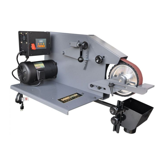
- Page 1 MODEL NO.: MI-16800 OPERATING MANUAL...
-
Page 2: Important Safety Instructions
Operating Instructions and Parts Manual 2 x 72-inch Square Wheel Belt Grinder IMPORTANT SAFETY INSTRUCTIONS - Misuse of this machine can cause serious injury. - For safety, machine must be set up, used and serviced properly. - Read, understand and follow instructions in the operator’s manual and all labels affixed to the machine. When setting up machine: - Always avoid using machine in damp or poorly lighted work areas. -
Page 3: Safety Requirements For Abrasive Grinding Machines
Maintain all machine tools with care. Follow all maintenance instructions for lubricating and the changing of accessories. No attempt shall be made to modify or have makeshift repairs done to the machine. This not only voids the warranty but also renders the machine unsafe. 10. - Page 4 Never use an abrasive which shows backing, nicks or cuts on the surface or edge or damage due to creasing or poor handling. 10. Always present the workpiece to the wheel while resting the workpiece firmly on the table. Failure to do so could result in damage to the workpiece or throwing of the workpiece off the wheel.
- Page 5 Specifications for Grinders Motor and Electricals Motor type Totally enclosed industrial Horsepower 1 HP Motor phase Single Motor voltage 115/230 V (prewired 115V) Cycle 60 Hz Listed FLA (full load amps) 11 / 5.5 A Motor speed 1,750 RPM Start capacitor 400MFD 125VAC Run capacitor 45 F 350VAC...
- Page 6 Dimensions Overall dimensions L x W x H 35-7/16 x 17 x 21-1/4 in. (900 x 433 x 540 mm) Shipping dimensions L x W x H 34-1/4 x 21-1/4 x 22-7/16 in. (870 x 540 x 570 mm) Weights Net weight 126 lb.
-
Page 7: Setup And Assembly
Hole spacing, All dimensions millimeters Figure 4-1 Adjustable handle 3/8x3/4” Read and understand all Flat washer 3/8” assembly instructions before attempting Platen assembly assembly. Failure to comply may cause serious Rail injury. Channel slide Note: Some illustrations in this manual may be Hand knobs 5/16x1 representative only, and not show your specific Socket hd cap screws 1/4x1/2... -
Page 8: Electrical Connections
Dust hood The dust hood can be positioned as needed below the contact wheel. Figure5-2: work rest and dust hood Electrical connections Electrical connections must be made by a qualified electrician in compliance with all relevant codes. This machine must be properly grounded to help prevent electrical shock and possible fatal injury. -
Page 9: Voltage Conversion
Before connecting to power source, be sure the Figure 6-1 switch is in off position. Voltage conversion Check with a The grinder is prewired for 115 volt input power, but qualified electrician or service personnel if the can be converted to 230 volt input, as follows. grounding instructions are not completely Single speed model understood, or if in doubt as to whether the tool... -
Page 10: Belt Tracking
Loosen knob and raise upper guard (see Figure Loosen knob and raise upper guard (see Figure 7-2). Open side panel by turning its knob and 7-2). Open side panel by turning its knob and lowering panel on its hinges. lowering panel on its hinges. Loosen clamp handle on head casting. - Page 11 Turn on grinder. Check belt tracking; belt Idler adjust / should remain centered on contact wheel. tracking Make further adjustments as needed according to step #3. If belt still does not track properly, increase belt tension and repeat steps 1 through 5. Belt tension Figure 7-3: Belt tracking Typical uses for the Square Wheel Belt Grinder...
-
Page 12: User Maintenance
User-maintenance Always disconnect power to machine before performing maintenance. Failure to comply may result in serious personal injury. Cleaning Shut off machine and disconnect before cleaning. Keep machine exterior clean and free of chips. Use a brush or vacuum to remove grinding dust and particles –... - Page 13 Troubleshooting Square Wheel Grinders Table 2 * WARNING: Some corrections may require a qualified electrician. Symptom Possible Cause Correction * Machine won’t start. No incoming power. Verify machine connections. Cord damaged. Replace cord. Building circuit breaker trips or fuse Verify that machine is on a circuit of correct size, blows.
-
Page 14: Replacement Parts
Replacement Parts... - Page 15 PARTS LIST FOR MI-16800 MI-16800-01 272-01 MI-16800-02 272-02 MI-16800-03 Door 272-03 x ” ” 2 i l i l l a ” 3 ” 2 ” 5 ” 2 c t i t i r...
- Page 16 PARTS LIST FOR MI-16800-33 Motor Assembly l l a l l a MI-16800-33-10 F001235 Phillips Pan Head Machine Screw #10-24 x 1/4 n i l MI-16800-33-15 F000233 Phillips Pan Head Machine Screw #10-24 x 1/2 MI-16800-33-16 F000231 Phillips Pan Head Machine Screw...
- Page 17 PARTS LIST FOR MI-16800-38 Control Switch Assembly c t i c t i MI-16800-38-10 VS-3810 c t i MI-16800-38-13 VS-3813 Control Panel w/ Digital Readout (includes MI-16800-38-16 F000231 Phillips Pan Head Machine Screw #10-24 x 3/8 MI-16800-38-17 F001235 Phillips Pan Head Machine Screw...
- Page 18 PARTS LIST FOR MI-16800-04 Idler Housing Casting Assembly e l l l l o PARTS LIST FOR MI-16800-05 Platen Assembly MI-16800-05-01 Platen l l a ” 3 ” 2 ” 2 ” 2...
- Page 19 PARTS LIST FOR MI-16800-06 Contact Wheel Assembly x ” ” 2 MI-16800-06-02 Shaft l l a PARTS LIST FOR MI-16800-40 Dust Hood Assembly MI-16800-40-01 4001 Rail MI-16800-40-02 4002 Channel MI-16800-40-03 4003 Scoop...
- Page 20 Electrical Connections Wiring diagram...
Need help?
Do you have a question about the MI-16800 and is the answer not in the manual?
Questions and answers