Table of Contents
Advertisement
Quick Links
Installation Instructions
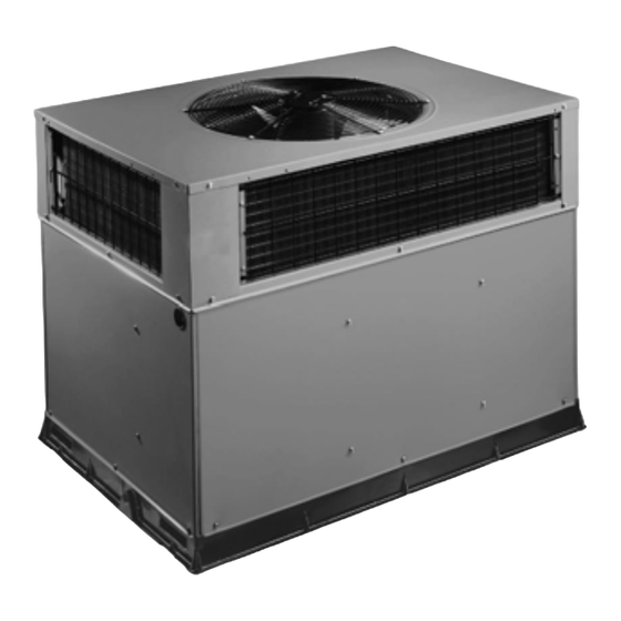
PACKAGED GAS/ELECTRIC UNIT
. . . . . . . . . . . . . . . . . . . . . . . . . . . . .
. . . . . . . . . . . . . . . . . . . . . . . . . . .
. . . . . . . . . . . . . . . . . . . . . . . .
. . . . . . . . . . . . . . . . . . . . . . . . . . . . .
. . . . . . . . . . . . . . . . . . . . . . . . .
. . . . . . . . . . . . . . . . . . . . . . .
Install Flue Hood
. . . . . . . . . . . . . . . . . . . . . . . .
. . . . . . . . . . . . . . . . . . . . . . . . . . .
. . . . . . . . . . . . . . . . . . . . . . . . . . . .
. . . . . . . . . . . . . . . . . . . . . . . . . . . . . . . . . .
Start--Up Heating & Make Adjustments
. . . . . . . . . . . . . . . . . . . . . . . . . . . . . . .
. . . . . . . . . . . . . . . . . . . . . . .
. . . . . . . . . . . . . . . . . . . . . . . . . . . . .
Start--Up Cooling & Make Adjustments
. . . . . . . . . . . . . . . . . . . . .
Airflow
. . . . . . . . . . . . . . . . . . . . . . . . . . . . . . . . . .
Printed in U.S.A.
PGN4 Series
TABLE OF CONTENTS
Page
. . . . . . . .
2
3
. . . . . . . . . . . . . . .
3
3
3
. . . . . . . . . . . . . . . . . . . .
3
4 -- 5
6
6 -- 7
. . . . . . . . . . . . . . . . . .
7
7 -- 8
8
. . . . . . . . . . . . . . . .
9 -- 10
. . . . . . . . . . .
10 -- 13
14
14
. . . . . . . . . . . . . . . . .
14
. .
14 -- 15
15
16
. . . . . . . . . . . . . .
17
17
. . . . . . . . . . . . . . . . . . .
17
. . . . . . .
18
18 -- 19
20
. . . . . . . . . . . . . . . . . . .
20
International Comfort Products, LLC
Indoor Blower and Motor
Outdoor & Indoor Coil, Condensate Drain Pan 22
AIRFLOW CHART
COOLING TROUBLESHOOTING GUIDE
HEATING TROUBLESHOOTING GUIDE
LED ERROR CODES GUIDE
CHECKLIST FORM
Lewisburg, TN. 37091
. . . . . . . . . . . . . . . . . . . . . . . . . . . . .
. . . . . . . . . . . . . . . . . . . . . . . . . . . . . . . . . .
. . . . . . . . . . . . . . . . . . . .
. . . . . . . . . . . . . . . . . . . .
. . . . . . . . . . . . . . . . . . . . . . . . . . . . . . .
. . . . . . . . . . . . . . . . . . . . . . . . . . . .
. . . . . . . . . . . . . . . . . . . . . . . . . . . . . .
. . . . . . . . . . . . . . . . . . . . . . . . .
. . . . . . . . . . . . . . .
. . . . . . . . . . . . . . . . . . . . . . . .
. . . . . . . . . . . . . . . . . . . . . . . . . . . . . . . . .
. . . . . . . . . . . . . . . . . . . . . . . . .
. . . . . . . . . . . . . . . . . . . . . . . .
. . . . . . . . . . . . . . . . . . . . . .
. . . . . . . . . . . . . . . . . .
. . . . . . . . . .
. . . . . . . . . . . . . . . . . . . . . . . . . .
462 01 2001 01
Page
21
21
21
22
. . . . . . .
22
22
22
22
.
23 -- 24
24
24
24
24
24 -- 25
26 -- 29
. . . . . . .
30
. . . . . . .
31
32
33
34
01- -28- -08
Advertisement
Table of Contents

Related Manuals for International comfort products PGN4 Series


Summary of Contents for International comfort products PGN4 Series
-
Page 1: Table Of Contents
........Sequence of Operation ....International Comfort Products, LLC Lewisburg, TN. 37091 462 01 2001 01 01- -28- -08 Printed in U.S.A. -
Page 2: Safe Installation Requirements
SAFE INSTALLATION REQUIREMENTS PACKAGED GAS / ELECTRIC UNIT FIGURE 1 Recognize safety information. This is the safety--alert symbol . When you see this symbol in instructions or manuals, be alert to the potential for personal injury. Understand the signal words DANGER, WARNING, CAUTION, and NOTE. -
Page 3: Receiving And Installation
RECEIVING AND INSTALLATION STEP 1 — Check Equipment Slab Mounting Details FIGURE 2 Identify Unit The unit model number and serial number are stamped on the unit information plate. Check this information against OPTIONAL OPTIONAL shipping papers. RETURN SUPPLY Inspect Shipment OPENING OPENING Inspect for shipping damage while unit is still on shipping... -
Page 4: Dimensions
FIGURE 3 MODEL SIZE 24- -36 DIMENSIONS UNIT CENTER OF GRAVITY HEIGHT IN. [MM] UNIT WEIGHT Model ELECTRICAL IN. [MM] Size CHARACTERISTICS “A” 208/230--1--60, 208/230--3--60 139.3 37 [940] 23.6 [599.4] 15.8 [401.3] 15.7 [398.8] 208/230--1--60, 208/230--3--60 144.7 37 [940] 23.6 [599.4] 15.8 [401.3] 15.7 [398.8] 208/230--1--60, 208/230--3--60... - Page 5 FIGURE 4 MODEL SIZE 42- -60 DIMENSIONS UNIT CENTER OF GRAVITY HEIGHT IN. [MM] UNIT WEIGHT Model ELECTRICAL IN. [MM] Size CHARACTERISTICS “A” 208/230--1--60, 208/230--3--60 197.3 46.98 [1193] 25.5 [647.7] 21.0 [533] 17.6 [447] 208/230--1--60, 208/230--3--60 205.5 46.98 [1193] 25.7 [652.8] 21.8 [553.7] 18.0 [457.2] 208/230--1--60, 208/230--3--60 218.2 50.98 [1295] 25.8 [655.3] 22.0 [558.8] 20.0 [508.0]...
-
Page 6: Provide Clearances
STEP 4 — Provide Clearances wear at hoist hooking points and load support areas. Brackets or straps showing any kind of wear in these areas The required minimum operating and service clearances must not be used and should be discarded. are shown in Figures 3 and 4. -
Page 7: Connect Condensate Drain
4. After unit is securely in place detach rigging straps. After the unit is placed on the roof curb or mounting pad, Remove corner posts screws, and rigging brackets remove the top crating. then reinstall screws. FIGURE 5 Unit Corner Weight (lbs) and Rigging Rigging Brackets are factory installed on 3---phase units only. -
Page 8: Install Gas Piping
For natural gas applications, the gas pressure at unit gas WARNING connection must not be less than 4.0 inches water column or greater than 13 inches water column while the unit is CARBON MONOXIDE POISONING HAZARD operating. For Propane applications, the gas pressure must not be less than 11.0 inches water column or greater than Failure to follow this warning could result in personal injury or death. -
Page 9: Install Duct Connections
NOTE: Pressure test the gas supply system after the gas Sediment Trap FIGURE 7 supply piping is connected to the gas valve. The supply piping must be disconnected from the gas valve during the testing of the piping systems when test pressure is in excess of 0.5 psig. -
Page 10: Install Electrical Connections
5. It is recommended that the base insulation around the non--standard filters must not exceed 0.08 inches water perimeter of the vertical return--air opening be secured column. to the base with aluminum tape. Applicable local codes 2. PGN424040 (2 ton cooling, 40,000 BTU/h heat) may use may require aluminum tape to prevent exposed 20x20x1 filter. - Page 11 See unit wiring label (Figure 11) and Figure 10 for reference Standard Connection when making high voltage connections. Proceed as follows Remove knockout hole located in the flue panel adjacent to to complete the high--voltage connections to the unit. the control access panel (see Figures 3 and 4). Remove the Single--phase units: rubber grommet from the installer’s packet (included with unit) and install grommet in the knockout opening.
- Page 12 FIGURE 11 208/230 - - 1 - - 60 WIRING DIAGRAM...
- Page 13 FIGURE 12 208/230 - - 3 - - 60 WIRING DIAGRAM...
-
Page 14: Pre- -Startup
PRE- -STARTUP Inspect for oil at all refrigerant tubing connections WARNING and on unit base. Detecting oil generally indicates a refrigerant leak. FIRE, EXPLOSION, ELECTRICAL SHOCK HAZARD Leak--test all refrigerant tubing connections using electronic leak detector, or liquid--soap solution. If Failure to follow this warning could result in personal a refrigerant leak is detected, see following Check injury or death. -
Page 15: Gas Input
Altitude Derate Multiplier for U.S.A. operation my occur when the burner orifices in the manifold Table 3 - - are misaligned. PERCENT OF ALTITUDE (ft) DE---RATE MULTIPLIER * DERATE Follow the lighting instructions on the heating section operation label (located inside the burner or blower access 0--- 2000 1.00 door) to start the heating section. - Page 16 NOTE: All other appliances that use the same meter must Burner Assembly FIGURE 13 be turned off when gas flow is measured at the meter. Proceed as follows: 1. Turn off gas supply to unit. 2. Remove pipe plug on manifold (see Figure 13) and connect manometer.
-
Page 17: Airflow And Temperature Rise
Check Burner Flame Heating Sequence of Operation With burner access panel removed, observe the unit (see Figures 11, 12, and unit wiring label.) heating operation. Watch the burner flames to see if they On a call for heating, terminal W of the thermostat is are light blue and soft in appearance, and that the flames energized, starting the induced--draft motor. -
Page 18: R--410A Charge
STEP 3 — Start- -up cooling and make adjustments NOTE: Allow system to operate a minimum of 15 minutes before checking or adjusting charge. Complete required procedures given Proceed as follows: Pre--Start--Up section before starting the unit. Do not jumper any safety devices when operating the unit. Do not 1. - Page 19 Table 6 - - Cooling Charging Chart...
-
Page 20: Sequence Of Operation
Indoor Airflow and Airflow Adjustments Interface Fan Board (IFB) FIGURE 16 CAUTION UNIT OPERATION HAZARD Failure to follow this caution may result in unit damage. For cooling operation, the recommended airflow is 350 to 450 cfm for each 12,000 BTU/h of rated cooling capacity. -
Page 21: Maintenance
MAINTENANCE To ensure continuing high performance and to minimize the 5. Ensure electric wires are not in contact with refrigerant tubing or sharp metal edges. possibility of premature equipment failure, periodic maintenance must be performed on this equipment. This 6. Check and inspect heating section before each heating unit should be inspected at least once each year by a season. -
Page 22: Flue Gas Passageways
Reassemble wheel into housing. Removal of Gas Train Reassemble motor into housing. Be sure To remove the gas train for servicing: setscrews are tightened on motor shaft flats and 1. Shut off main gas valve. not on round part of shaft. 2. -
Page 23: Outdoor Fan
Outdoor Fan Blower Housing and Flue Collector Box FIGURE 18 CAUTION UNIT OPERATION HAZARD Integrated Gas Unit Failure to follow this caution may result in damage to Controller unit components. (IGC) Keep the condenser fan free from all obstructions to Interface Fan ensure proper cooling operation. -
Page 24: Gas Input
electronic leak--detector, halide torch, or liquid--soap 1. Turn off all power to unit. solution. If a refrigerant leak is detected, refer to the 2. Disconnect leads on switch. Check for Refrigerant Leaks section. 3. Apply ohm meter leads across switch. You should have If no refrigerant leaks are found and low cooling continuity on a good switch. - Page 25 Servicing Systems on Roofs with Synthetic Materials 3. Perform required service. POE (polyolester) compressor lubricants are known to 4. Remove and dispose of any oil contaminated material cause long term damage to some synthetic roofing per local codes. materials. Liquid Line Filter Drier Exposure, even if immediately cleaned up, may cause This filter drier is specifically designed to operate with embrittlement (leading to cracking) to occur in one year...
- Page 26 Table 8—Dry Coil Air Delivery* - - Horizontal and Downflow Discharge (Deduct 10% for 208 Volts) External Static Pressure (Inches Water Column) Heating Rise Motor Wire Model Range Speed Color ---- ---- ---- ---- ---- Blue Heating Rise ( Heating Rise ( ---- ---- ----...
- Page 27 External Static Pressure (Inches Water Column) Heating Rise Motor Wire Heating Rise Motor Wire Model Model Range Speed Color Range Speed Color 1206 1151 1085 1033 Blue Heating Rise ( Heating Rise ( 1369 1317 1262 1208 1152 1095 1037 Heating Rise ( Med--Low Pink...
- Page 28 External Static Pressure (Inches Water Column) Heating Rise Motor Wire Heating Rise Motor Wire Model Model Range Speed Color Range Speed Color 1445 1389 1341 1281 1236 1189 1139 1072 1027 Blue Heating Rise ( Heating Rise ( 1678 1635 1602 1558 1513...
- Page 29 External Static Pressure (Inches Water Column) Heating Rise Motor Wire Heating Rise Motor Wire Model Model Range Speed Color Range Speed Color 1448 1362 1296 1226 1168 1108 1071 Blue Heating Rise ( Heating Rise ( 1722 1675 1614 1543 1499 1442 1408...
- Page 30 Table 11—Troubleshooting Guide - - Cooling SYMPTOM CAUSE REMEDY Power failure Call power company Fuse blown or circuit breaker tripped Replace fuse or reset circuit breaker Defective contactor, transformer, or high--pres- Replace component sure, loss--of--charge or low--pressure switch Compressor and condenser fan will not start.
- Page 31 Table 12—Troubleshooting Guide–Heating SYMPTOM CAUSE REMEDY Water in gas line Drain. Install drip leg. Check power supply fuses, wiring or No power to furnace circuit breaker. Check transformer. NOTE: Some transformers have No 20--v power supply to control circuit internal over--current protection that requires a cool--down period to reset.
- Page 32 Table 13—Troubleshooting Guide–LED Error Codes SYMPTOM CAUSE REMEDY Check 5--amp fuse son IGC*, power to unit, 24--v circuit breaker, and transformer. Units Hardware failure without a 24--v circuit breaker have an internal Loss of power to control module (IGC)*. (LED OFF) overload in the 24--v transformer.
-
Page 33: R--410A Quick Reference Guide
R- -410A QUICK REFERENCE GUIDE • R--410A refrigerant operates at 50% -- 70% higher pressures than R--22. Be sure that servicing equipment and replacement components are designed to operate with R--410A. • R--410A refrigerant cylinders are rose colored. • Recovery cylinder service pressure rating must be 400 psig, DOT 4BA400 or DOT BW400. •... - Page 34 START- -UP CHECKLIST (Remove and Store in Job File) 1. Preliminary Information Model Number: Serial Number: Date: Technician: 2. Pre--Start--Up ____ Verify that all packing materials have been removed from unit ____ Check all electrical connections and terminals for tightness ____ Check gas piping for leaks ____ Check that the indoor (evaporator) air filter is clean and in place ____ Verify that the unit installation is level...
Need help?
Do you have a question about the PGN4 Series and is the answer not in the manual?
Questions and answers