Table of Contents
Advertisement
Quick Links
Installation Instructions
PACKAGED AIR CONDITIONERS
. . . . . . . . . . . . . . . . . . . . . . . . . . . . .
. . . . . . . . . . . . . . . . . . . . . . . . . . . . .
. . . . . . . . . . . . . . . . . . . . . . . . . .
. . . . . . . . . . . . . . . . . . . . . . . . . . .
. . . . . . . . . . . . . . . . . . . . . . .
. . . . . . . . . . . . . . . . . . . . . . . . .
. . . . . . . . . . . . . . . . . . . . . . . . . . . . . . .
. . . . . . . . . . . . . . . . . . . . . . .
. . . . . . . . . . . . . . . . . . . . . . . . . . . .
. . . . . . . . . . . . . . . . . . . . . . . . . . . . . . . . . .
Printed in U.S.A.
PAN3 Series
Single Phase
TABLE OF CONTENTS
Page
. . . . . . . .
2
2
. . . . . . . . . . . . . . .
2
2
2
3
3
3 -- 4
5 -- 6
. . . . . . . . . . . . . . . . .
7
. . . . . . . . . . . . . . . . . . . . .
8
8
. . . . . . . . . . . . . . .
9 --10
11
11
. . . . . . . . . . . . . . . . . . .
11
International Comfort Products, LLC
Lewisburg, TN. 37091
. . . . . . . . . . . . . . . . . . . . . . . .
. . . . . . . . . . . . . . . . . . . . . . . . . . . . .
. . . . . . . . . . . . . . . . . . . . . . .
. . . . . . . . . . . . . . . . . . . . . . . . . .
. . . . . . . . . . . . . . . . . . . . . . . . . . . . .
. . . . . . . . . . . . . . . . . . . . . . . . . . . . . . . . . . . .
. . . . . . . . . . . . . . . . . . . . . .
. . . . . . . . . . . . . . . . . . . . . . . . . . . . . . . . .
. . . . . . . . . . . . . . . . . . . . . . . . . . . . . . . .
. . . . . . . . . . . . . . . . . . . . . . . .
. . . . . . . . . . . . . . . . . . . . . .
519 01 1701 01
11
12
. . . . .
13
. . . . . . . . . . .
13
. . . . . . . . . . . . . . . .
13
14
14
15
16
16
.
16
16
. . . . . . . . . . . . . . . . . .
17
17
. . . . . . . . . . . . . . . .
17
18
19
01- -28- -08
Advertisement
Table of Contents

Related Manuals for International comfort products PAN324


Summary of Contents for International comfort products PAN324
-
Page 1: Table Of Contents
....START--UP CHECKLIST ..... . International Comfort Products, LLC Lewisburg, TN. 37091 519 01 1701 01 01- -28- -08 Printed in U.S.A. -
Page 2: Safe Installation Requirements
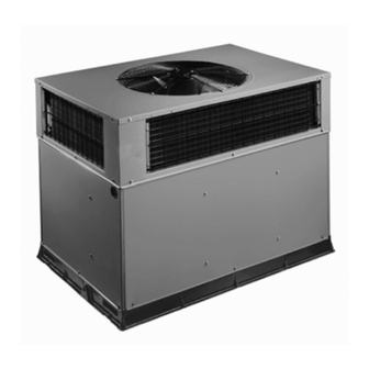
SAFE INSTALLATION REQUIREMENTS We require these instructions as a minimum for a safe installation. WARNING PAN3 AIR CONDITIONING UNIT FIGURE 1 ELECTRICAL SHOCK HAZARD Failure to follow this warning could result in personal injury or death. Before installing or servicing system, turn off power supply to the unit and install lockout tag. -
Page 3: Provide Clearances
2 in. beyond the casing on all 4 sides of the unit. Do not For horizontal applications, unit is provided with flanges on secure the unit to the slab except when required by local the horizontal openings. All ductwork should be secured to codes. -
Page 4: Rig And Place Unit
WARNING WARNING PROPERTY DAMAGE HAZARD PROPERTY DAMAGE HAZARD Failure to follow this warning could result in personal Failure to follow this warning could result in personal injury/death or property damage. injury/death or property damage. Rigging brackets for one unit use only. When Do not strip screws when re--securing the unit. - Page 5 FIGURE 3 PAN324- -36 DIMENSIONS REQUIRED CLEARANCE TO COMBUSTIBLE MATL. REQUIRED CLEARANCE FOR OPERATION AND SERVICING INCHES [mm] (R efer to M aximum O perating C learances ) INCHES [mm] EVAP. COIL ACCESS SIDE............36.00 [914.0] POWER ENTRY SIDE..............42.00 [1066.8] TOP OF UNIT...................14.00 [355.6] (EXCEPT FOR NEC REQUIREMENTS) DUCT SIDE OF UNIT.................2.00 [50.8]...
-
Page 6: Dimensions
FIGURE 4 PAN342- -60 DIMENSIONS REQUIRED CLEARANCE TO COMBUSTIBLE MATL. REQUIRED CLEARANCE FOR OPERATION AND SERVICING INCHES [mm] (R efer to M aximum O perating C learances ) EVAP. COIL ACCESS SIDE............36.00 [914.0] INCHES [mm] POWER ENTRY SIDE..............42.00 [1066.8] TOP OF UNIT...................14.00 [355.6] (EXCEPT FOR NEC REQUIREMENTS) DUCT SIDE OF UNIT.................2.00 [50.8] UNIT TOP ..................48.00 [1219.2]... -
Page 7: Filter Data And Corner Weights
Table Filter Data - - PAN324- -60 1— UNIT SIZE RETURN- -AIR FILTERS, IN. (MM)* 20x20x1 20x30x1 (610x762x25) 24x36x1 (610x914x25) (508X508X25) Throwaway Required filter sizes shown are based on the larger of the ARI (Air Conditioning and Refrigeration Institute) rated cooling airflow or the heating airflow velocity of 300 ft/minute for throwaway type. -
Page 8: Connect Condensate Drain
Step 6—Connect Condensate Drain sheet metal sleeve inside duct. Heat resistant duct connector (or sheet metal sleeve) must extend 24--in. from NOTE: When installing condensate drain connection be electric heater element. sure to comply with local codes and restrictions. 3. Size ductwork for cooling air quantity (cfm). The The PAN3 disposes of condensate water through a 3/4 in. -
Page 9: Install Electrical Connections
NOTE: The design and installation of the duct system must 6. Adequately insulate and weatherproof all ductwork located outdoors. Insulate ducts passing through be in accordance with the standards of the NFPA for unconditioned space, and use vapor barrier in installation of nonresidence--type air conditioning and accordance with latest issue of Sheet Metal and Air ventilating systems, NFPA 90A or residence--type, NFPA... - Page 10 The unit must have a separate electrical service with a NOTE:If auxiliary electric heat is installed, there may be field--supplied, waterproof disconnect switch mounted at, or additional low voltage control wires. within sight from the unit. Refer to the unit rating plate, NEC Ensure the leads are long enough to be routed into the and local codes for maximum fuse/circuit breaker size and low--voltage splice box (located below right side of control...
-
Page 11: Pre--Start--Up
PRE- -START- -UP Make sure that all tools and miscellaneous loose parts have been removed. WARNING Fan Blade Clearance FIGURE 10 FIRE, EXPLOSION, ELECTRICAL SHOCK HAZARD FAN GRILLE MOTOR Failure to follow this warning could result in personal injury or death. 1. -
Page 12: Wiring Diagrams
FIGURE 11 PAN324- -60 Wiring Diagram... -
Page 13: Checking And Adjusting Refrigerant Charge
CHECKING AND ADJUSTING REFRIGERANT CHARGE INDOOR AIRFLOW AND AIRFLOW ADJUSTMENTS The refrigerant system is fully charged with R--22 NOTE: For cooling operation, the recommended airflow is refrigerant and is tested and factory sealed. Allow system 350 to 450 cfm for each 12,000 Btuh of rated cooling to operate a minimum of 10 minutes before checking or capacity. -
Page 14: Cooling Charging Chart
breaks the circuit between thermostat terminal R to blower motor stops. The unit is in a standby condition, terminals Y and G. These open circuits deenergize waiting for the next call for cooling from the room contactor coil C and relay coil TDR. The condenser and thermostat. -
Page 15: Maintenance
Dry Coil Air Delivery* — Horizontal Discharge Table 6— (Deduct 10% for 208- -Volt Operation) External Static Pressure (in. wc) Motor Speed Unit Watts ---- ---- Watts PAN324 Medium 1195 1155 1100 1028 Watts High 1484 1421 1368 1279 1185... -
Page 16: Air Filter
2. Inspect indoor coil, drain pan, and condensate drain Lift wheel from housing. When handling and/or each cooling season for cleanliness. Clean when cleaning blower wheel, be sure not to disturb necessary. balance weights (clips) on blower wheel vanes. Remove caked--on dirt from wheel and housing 3. -
Page 17: Electrical Controls And Wiring
5. When replacing fan blade, position blade so that the If oil is detected or if low performance is suspected, leak test hub is 1/8 in. (3mm) away from the motor end (1/8 in. all refrigerant tubing using an electronic leak detector, or (3mm) of motor shaft will be visible) (See Fig. - Page 18 Table 7—Troubleshooting Chart SYMPTOM CAUSE REMEDY Power failure Call power company Fuse blown or circuit breaker tripped Replace fuse or reset circuit breaker Defective contactor, transformer, control relay, or high--pressure, loss--of--charge or low--pressure Compressor and outdoor fan will not Replace component start switch Insufficient line voltage...
-
Page 19: Start-Up Checklist
START-UP CHECKLIST (Remove and Store in Job File) I. Preliminary Information MODEL NO.:_________________________________ SERIAL NO.:__________________________________ DATE:_______________________________________ TECHNICIAN:_________________________________ II. PRE-START-UP (Insert checkmark in box as each item is completed) ( ) VERIFY THAT ALL PACKING MATERIALS HAVE BEEN REMOVED FROM UNIT ( ) REMOVE ALL SHIPPING HOLD DOWN BOLTS AND BRACKETS PER INSTALLATION INSTRUCTIONS ( ) CHECK ALL ELECTRICAL CONNECTIONS AND TERMINALS FOR TIGHTNESS ( ) CHECK THAT INDOOR (EVAPORATOR) AIR FILTER IS CLEAN AND IN PLACE...
Need help?
Do you have a question about the PAN324 and is the answer not in the manual?
Questions and answers