
Related Manuals for Fujitsu AGYG09KVCB


Summary of Contents for Fujitsu AGYG09KVCB
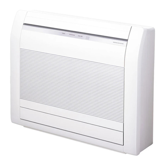
- Page 1 AIR CONDITIONER Floor type SERVICE MANUAL INDOOR AGYG09KVCB AGYG12KVCB AGYG14KVCB OUTDOOR AOYG09KVCBN AOYG12KVCBN AOYG14KVCBN SR_AG002EF_03 2020.11.25...
- Page 2 • Product specifications and design are subject to change without notice for future improvement. • For further details, please check with our authorized dealer. Trademarks ™ FGLair is trademark of Fujitsu General Limited in the United States, other countries or both. ™ Google Play is trademark of Google Inc. ®...
- Page 3 CONTENTS 1. GENERAL INFORMATION 2. TECHNICAL DATA AND PARTS LIST 3. TROUBLESHOOTING 4. CONTROL AND FUNCTIONS 5. FILED WORKING...
- Page 5 1. GENERAL INFORMATION 2020.10.05 SR_CH01_AG002EF_01...
- Page 6 CONTENTS 1. GENERAL INFORMATION 1. Specifications....................01-1 1-1. Indoor unit ........................01-1 1-2. Outdoor unit........................01-3 2. Dimensions....................01-4 2-1. Indoor unit ........................01-4 2-2. Outdoor unit........................01-6...
- Page 7 1. Specifications 1-1. Indoor unit Floor type Type Inverter heat pump Model name AGYG09KVCB AGYG12KVCB AGYG14KVCB Power supply 230 V ~ 50 Hz Available voltage range 198—264 V 2.50 3.50 4.20 Rated Btu/h 8,500 11,900 14,300 Cooling 0.9—4.3 0.9—4.3 0.9—5.2 Min.—Max.
- Page 8 Model name AGYG09KVCB AGYG12KVCB AGYG14KVCB Cooling A+++ A+++ Energy efficiency class Heating (Average) Cooling 2.5 (35 °C) 3.5 (35 °C) 4.2 (35 °C) Pdesign Heating (Average) 3.0 (-10 °C) 3.6 (-10 °C) 4.2 (-10 °C) SEER Cooling 8.60 8.50 8.10...
- Page 9 1-2. Outdoor unit Type Inverter heat pump Model name AOYG09KVCBN AOYG12KVCBN AOYG14KVCBN Power supply 230 V ~ 50 Hz Available voltage range 198—264 V Starting current Cooling 1,550 1,830 2,210 Airflow rate Heating 1,690 2,100 2,100 Type × Q'ty Propeller × 1 Motor output Cooling Sound pressure level *1...
- Page 10 2. Dimensions 2-1. Indoor unit ¢ Models: AGYG09KVCB, AGYG12KVCB, and AGYG14KVCB Unit: mm Side view Front view Installation space 100 or more 80 or more 80 or more 50 or more 150 or below from the floor - (01-4) - 2-1.
- Page 11 PROHIBITED Grating WARNING • The appliance shall be installed, operated and stored in a room with a floor area larger than X Minimum room area Amount of refrigerant charge M (kg) X (m M ≤ 1.22 1.22 < M ≤ 1.23 12.99 1.23 <...
- Page 12 2-2. Outdoor unit ¢ Models: AOYG09KVCBN, AOYG12KVCBN, and AOYG14KVCBN Unit: mm 4-M10 hole Pitch of bolts for installation Top view Side view Front view Side view Airflow Drain port Ø42 Bottom view Side view (Valve part) - (01-6) - 2-2. Outdoor unit 2.
- Page 13 2. TECHNICAL DATA AND PARTS LIST 2020.11.25 SR_CH02_AG002EF_02...
- Page 14 CONTENTS 2. TECHNICAL DATA AND PARTS LIST 1. Precautions....................02-1 2. Indoor unit parts list..................02-2 2-1. Models: AGYG09KVCB, AGYG12KVCB, and AGYG14KVCB........02-2 3. Outdoor unit parts list.................02-8 3-1. Models: AOYG09KVCBN, AOYG12KVCBN, and AOYG14KVCBN .......02-8 4. Accessories ....................02-12 4-1. Indoor unit ........................02-12 4-2. Outdoor unit........................02-13 5.
- Page 15 • Service parts information and design are subject to change without notice for product improve- ment. • For the latest information of the service parts, refer to our Service Portal. https://fujitsu-general.force.com/portal/ • Precise figure of the service parts listed in this manual may differ from the actual service parts. - (02-1) -...
- Page 16 2. Indoor unit parts list 2-1. Models: AGYG09KVCB, AGYG12KVCB, and AGYG14KVCB ¢ Exterior parts and chassis - (02-2) - 2-1. Models: AGYG09KVCB, AGYG12KVCB, and AGYG14KVCB 2. Indoor unit parts list...
- Page 17 Terminal cover — — Front panel — — Terminal bracket (COM) — — Control box shield — — Control box cover — — Control box — - (02-3) - 2-1. Models: AGYG09KVCB, AGYG12KVCB, and AGYG14KVCB 2. Indoor unit parts list...
- Page 18 ¢ Casing - (02-4) - 2-1. Models: AGYG09KVCB, AGYG12KVCB, and AGYG14KVCB 2. Indoor unit parts list...
- Page 19 (P1001 on Indicator PCB—P1000 on Indicator PCB) 9900384043 Step motor (Up/Down) ♦ — Casing — — Casing reinforcement — — Display cover — — Display case — — Switch cover — - (02-5) - 2-1. Models: AGYG09KVCB, AGYG12KVCB, and AGYG14KVCB 2. Indoor unit parts list...
- Page 20 ¢ Drain pan - (02-6) - 2-1. Models: AGYG09KVCB, AGYG12KVCB, and AGYG14KVCB 2. Indoor unit parts list...
- Page 21 Step motor (Damper lock L) ♦ 9900424015 Micro switch (Limit) ♦ 9900384050 Step motor (Damper) ♦ — Drain pan U — — Drain pan Z — - (02-7) - 2-1. Models: AGYG09KVCB, AGYG12KVCB, and AGYG14KVCB 2. Indoor unit parts list...
- Page 22 3. Outdoor unit parts list 3-1. Models: AOYG09KVCBN, AOYG12KVCBN, and AOYG14KVCBN ¢ Exterior parts and Chassis - (02-8) - 3-1. Models: AOYG09KVCBN, AOYG12KVCBN, and AOYG14KVCBN 3. Outdoor unit parts list...
- Page 23 Item no. Part no. Part name Service part 9322556066 Top panel assy ♦ 9900850012 Thermistor (Outdoor temp.) ♦ 9377854025 Protective net ♦ 9322327000 Thermistor holder ♦ 9322552099 Cabinet right assy ♦ 9322570024 Switch cover assy ♦ 9323540033 Heater holder A ♦...
- Page 24 ¢ Compressor - (02-10) - 3-1. Models: AOYG09KVCBN, AOYG12KVCBN, and AOYG14KVCBN 3. Outdoor unit parts list...
- Page 25 Item no. Part no. Part name Service part 9322431004 Compressor assy (09 model) ♦ 9810523006 Compressor assy (12, 14 models) ♦ 9322445018 4-way valve assy (09 model) ♦ 9383129063 4-way valve assy (12, 14 models) ♦ 9970194023 Solenoid ♦ 9322435002 Muffler (09 model) ♦...
- Page 26 4. Accessories 4-1. Indoor unit ¢ Models: AGYG09KVCB, AGYG12KVCB, and AGYG14KVCB Part name Exterior Q’ty Part name Exterior Q’ty Operating manual (CD- Operating manual ROM) Installation manual Cloth tape Wall hook bracket Tapping screws (large) Remote controller Tapping screws (small)
- Page 27 4-2. Outdoor unit ¢ Models: AOYG09KVCBN, AOYG12KVCBN, and AOYG14KVCBN Part name Exterior Q’ty Part name Exterior Q’ty Installation manual - (02-13) - 4-2. Outdoor unit 4. Accessories...
- Page 28 5. Optional parts 5-1. Indoor unit ¢ Controllers Exterior Part name Model name Summary Easy finger touch operation with LCD Wired remote panel. Backlit LCD enables easy UTY-RNRYZ* controller operation in a dark room. Wire type: Non-polar 2-wire High visibility and easy operation. Room temperature can be accurately Wired remote controlled using the built-in thermo...
- Page 29 ¢ Others Exterior Part name Model name Summary Required when external device is External connected. UTY-XWZXZ5 connect kit Communication Use to connect Non-polar 2-core wired UTY-TWRXZ3 remote controller. Remotely manage an air conditioning system using mobile devices such as Wireless LAN UTY-TFSXZ1 smartphones and tablets.
- Page 30 6. Refrigerant system diagrams 6-1. Model: AOYG09KVCBN Heat exchanger 3-Way ( INDOOR ) valve 2-Way valve Muffler Muffler 4-Way valve Strainer Expansion valve Heat exchanger Strainer ( OUTDOOR ) Cooling Heating : Thermistor (Discharge Temp.) : Thermistor (Outdoor Temp.) : Thermistor (Heat Exchanger Out Temp.) : Thermistor (Room Temp.) : Thermistor (Pipe Temp.) - (02-16) -...
- Page 31 6-2. Models: AOYG12KVCBN and AOYG14KVCBN Heat exchanger 3-Way ( INDOOR ) valve Pressure switch 2-Way valve Muffler Muffler 4-Way valve Strainer Expansion valve Heat exchanger Strainer ( OUTDOOR ) Cooling Heating : Thermistor (Discharge Temp.) : Thermistor (Outdoor Temp.) : Thermistor (Heat Exchanger Out Temp.) : Thermistor (Room Temp.) : Thermistor (Pipe Temp.) - (02-17) -...
- Page 32 7. Wiring diagrams 7-1. Indoor unit ¢ Models: AGYG09KVCB, AGYG12KVCB, and AGYG14KVCB - (02-18) - 7-1. Indoor unit 7. Wiring diagrams...
- Page 33 7-2. Outdoor unit ¢ Model: AOYG09KVCBN ¢ Models: AOYG12KVCBN and AOYG14KVCBN - (02-19) - 7-2. Outdoor unit 7. Wiring diagrams...
- Page 34 8. PC board diagrams 8-1. Models: AGYG09KVCB, AGYG12KVCB, and AGYG14KVCB CONTROL UNIT 09 model : EZ-0206HSE INDICATOR PCB 12 model : EZ-0207HSE K20AE-2000HSE-D0 EMI FILTER 14 model : EZ-0208HSE GRFC-8 2 TURNS P1002 JB20-09HG UL1430 AWG22 BLACK WHITE 3.15A POWER SOURCE...
- Page 35 8-2. Models: AOYG09KVCBN, AOYG12KVCBN, and AOYG14KVCBN INVERTER ASSEMBLY 09 model : EZ-020LHUE 12, 14 models : EZ020WHUE EMI FILTER KRFC-13 EMI FILTER EMI FILTER 2 TURNS KRFC-13 KRFC-13 INDOOR UNIR 2 TURNS 1 TURNE UL3271 AWG16 COMPRESSOR W400 UL1015 AWG20 UL3271 AWG16 W103 Winding Resistance...
- Page 36 - (02-22) - 8-2. Models: AOYG09KVCBN, AOYG12KVCBN, and AOYG14KVCBN 8. PC board diagrams...
- Page 37 3. TROUBLESHOOTING 2020.11.11 SR_CH03_AG002EF_01...
- Page 38 CONTENTS 3. TROUBLESHOOTING 1. Error code ....................03-1 1-1. Error code table (Indoor unit and wired remote controller)..........03-1 2. Troubleshooting with error code ...............03-2 2-1. E: 11. Serial communication error (Serial reverse transfer error) (Outdoor unit).....03-2 2-2. E: 11. Serial communication error (Serial forward transfer error) (Indoor unit) ....03-4 2-3.
- Page 39 CONTENTS (continued) 5-1. Indoor unit ........................03-44 5-2. Outdoor unit........................03-45...
- Page 41 1. Error code 1-1. Error code table (Indoor unit and wired remote controller) The operation, timer, and economy indicators operate according to the error contents. For confirmation of the error contents, refer the flashing pattern as follows. Indoor unit display Wired remote Error contents...
- Page 42 2. Troubleshooting with error code 2-1. E: 11. Serial communication error (Serial reverse transfer error) (Outdoor unit) Operation indicator 1 time flash Timer indicator 1 time flash Indicator Indoor unit Economy indicator Continuous flash Error code E: 11 Main PCB When the indoor unit cannot receive the serial signal from outdoor unit more than 2 minutes after power on, Detective actuator...
- Page 43 Check point 4. Check serial signal (Reverse transfer signal) Check serial signal (Reverse transfer signal) GREEN WHITE BLACK WHITE BLACK • Check if indicated value swings between AC 70 V and AC 130 V at the outdoor unit terminal 1 —3.
- Page 44 2-2. E: 11. Serial communication error (Serial forward transfer error) (Indoor unit) Operation indicator 1 time flash Timer indicator 1 time flash Indicator Indoor unit Economy indicator Continuous flash Error code E: 11 Main PCB Indoor unit When the outdoor unit cannot properly receive the serial Detective actuator Fan motor signal from indoor unit for 10 seconds or more.
- Page 45 Check point 4. Check serial signal (Forward transfer signal) Check serial signal (Forward transfer signal) GREEN WHITE BLACK WHITE BLACK • Check if indicated value swings between AC 30 V and AC 130 V at outdoor unit terminal 2—3. • If it is abnormal, replace main PCB.
- Page 46 2-3. E: 12. Wired remote controller communication error (Indoor unit) Operation indicator 1 time flash Timer indicator 2 time flash Indicator Indoor unit Economy indicator Continuous flash Error code E: 12 Indoor unit Main PCB When the indoor unit cannot receive the signal from Detective actuator Wired remote controller more than 1 minute during Wired remote control...
- Page 47 2-4. E: 32. Indoor unit main PCB error (Indoor unit) Operation indicator 3 time flash Timer indicator 2 time flash Indicator Indoor unit Economy indicator Continuous flash Error code E: 32 When power is on and there is some below case. Detective actuator Indoor unit main PCB...
- Page 48 2-5. E: 35. MANUAL AUTO button error (Indoor unit) Operation indicator 3 time flash Timer indicator 5 time flash Indicator Indoor unit Economy indicator Continuous flash Error code E: 35 Indoor unit controller PCB When the MANUAL AUTO button becomes on for Detective actuator Indicator PCB consecutive 60 or more seconds.
- Page 49 2-6. E: 41. Room temperature sensor error (Indoor unit) Operation indicator 4 time flash Timer indicator 1 time flash Indicator Indoor unit Economy indicator Continuous flash Error code E: 41 Indoor unit main PCB Room temperature thermistor is open or short is Detective actuator detected always.
- Page 50 2-7. E: 42. Indoor unit heat exchanger sensor error (Indoor unit) Operation indicator 4 time flash Timer indicator 2 time flash Indicator Indoor unit Economy indicator Continuous flash Error code E: 42 Indoor unit main PCB When heat exchanger temperature thermistor open or Detective actuator Heat exchanger temperature short circuit is detected.
- Page 51 2-8. E: 45. Refrigerant leakage sensor error (Indoor unit) Operation indicator 4 time flash Timer indicator 5 time flash Indicator Indoor unit Economy indicator Continuous flash Error code E: 45 When refrigerant leakage sensor open, short circuit, or Detective actuator Refrigerant leakage sensor abnormal voltage of drive circuits detected.
- Page 52 2-9. E: 45. Refrigerant leakage sensor deterioration (Indoor unit) Operation indicator 4 time flash Timer indicator 5 time flash Indicator Indoor unit Economy indicator Continuous flash Error code E: 45 When refrigerant leakage sensor open, short circuit, or Detective actuator Refrigerant leakage sensor abnormal voltage of drive circuits detected.
- Page 53 2-10. E: 51. Indoor unit fan motor error (Indoor unit) Operation indicator 5 time flash Timer indicator 1 time flash Indicator Indoor unit Economy indicator Continuous flash Error code E: 51 main PCB When the condition that actual frequency of indoor fan is Detective actuator Indoor unit below 1/3 of target frequency is continued more than 56...
- Page 54 2-11. E: 57. Damper (Open/Close) detection limit switch error Operation indicator 5 time flash Timer indicator 7 time flash Indicator Indoor unit Economy indicator Continuous flash Error code E: 57 Indoor unit main PCB • When limit switch were not able to detect the close though the damper close.(Upper air flow) Limit switch Detective actuator...
- Page 55 2-12. E: 57. Damper error (Damper(Open/Close) simultaneous detection limit switch error) (Indoor unit) Operation indicator 5 time flash Timer indicator 7 time flash Indicator Indoor unit Economy indicator Continuous flash Error code E: 57 Indoor unit main PCB When the limit switch detects open and close at the Detective actuator simultaneous.
- Page 56 2-13. E: 62. Outdoor unit main PCB error (Outdoor unit) Operation indicator 6 time flash Timer indicator 2 time flash Indicator Indoor unit Economy indicator Continuous flash Error code E: 62 Access to EEPROM failed due to some cause after Detective actuator Outdoor unit Main PCB...
- Page 57 2-14. E: 71. Discharge thermistor error (Outdoor unit) Operation indicator 7 time flash Timer indicator 1 time flash Indicator Indoor unit Economy indicator Continuous flash Error code E: 71 Outdoor unit main PCB When discharge pipe temperature thermistor open or Detective actuator short circuit is detected at power on or while running the Discharge pipe temperature...
- Page 58 2-15. E: 73. Outdoor unit heat exchanger thermistor error (Outdoor unit) Operation indicator 7 time flash Timer indicator 3 time flash Indicator Indoor unit Economy indicator Continuous flash Error code E: 73 Outdoor unit main PCB When heat exchanger temperature thermistor open or Detective actuator short circuit is detected at power on or while running the Heat exchanger temperature...
- Page 59 2-16. E: 74. Outdoor temperature thermistor error (Outdoor unit) Operation indicator 7 time flash Timer indicator 4 time flash Indicator Indoor unit Economy indicator Continuous flash Error code E: 74 Outdoor unit main PCB When outdoor temperature thermistor open or short Detective actuator circuit is detected at power on or while running the Outdoor temperature thermistor...
- Page 60 2-17. E: 84. Current sensor error (Outdoor unit) Operation indicator 8 time flash Timer indicator 4 time flash Indicator Indoor unit Economy indicator Continuous flash Error code E: 84 When input current sensor has detected 0 A, while inverter compressor is operating at higher than 56 rps, Detective actuator Outdoor unit main PCB...
- Page 61 2-18. E: 94. Trip detection (Outdoor unit) Operation indicator 9 time flash Timer indicator 4 time flash Indicator Indoor unit Economy indicator Continuous flash Error code E: 94 Main PCB Protection stop by over-current generation after inverter compressor start processing completed generated consecutively 10 times.
- Page 62 2-19. E: 95. Compressor motor control error (Outdoor unit) Operation indicator 9 time flash Timer indicator 5 time flash Indicator Indoor unit Economy indicator Continuous flash Error code E: 95 Main PCB 1. When running the compressor, if the detected rotor location is out of phase with actual rotor location more than 90°, the compressor stops.
- Page 63 2-20. E: 97. Outdoor unit fan motor error (Outdoor unit) Operation indicator 9 time flash Timer indicator 7 time flash Indicator Indoor unit Economy indicator Continuous flash Error code E: 97 Main PCB 1. When outdoor fan rotation speed is less than 100 rpm in 20 seconds after fan motor starts, fan motor stops.
- Page 64 2-21. E: 99. 4-way valve error (Outdoor unit) Operation indicator 9 time flash Timer indicator 9 time flash Indicator Indoor unit Economy indicator Continuous flash Error code E: 99 Indoor unit main PCB When the indoor heat exchanger temperature is compared with the room temperature, and either Heat exchanger temperature following condition is detected continuously two times,...
- Page 65 Check point 4. Check the solenoid coil and 4-way valve NOTE: Refer solenoid coil and 4-way valve in "Service parts information" on page 03-36. • Solenoid coil Remove CN30 (for 09/12 model) and CN500 (for 14 model) from PCB and check the resistance value of coil.
- Page 66 2-22. E: A1. Discharge temperature error (Outdoor unit) Operation indicator 10 time flash Timer indicator 1 time flash Indicator Indoor unit Economy indicator Continuous flash Error code E: A1 Outdoor unit main PCB Protection stop by discharge temperature ≥ 110 °C Detective actuator during compressor operation generated 2 times within Discharge temperature thermistor...
- Page 67 Check point 5. Check the refrigerant amount Check the refrigerant leakage. ↓ Check point 6. Replace main PCB If check point 1 to 5 do not improve the symptom, replace the main PCB. ↓ - (03-27) - 2-22. E: A1. Discharge temperature error (Outdoor unit) 2.
- Page 68 2-23. E: A8. Refrigerant leakage sensor error (Indoor unit) Operation indicator 10 time flash Timer indicator 8 time flash Indicator Indoor unit Economy indicator Continuous flash Error code E: A8 Detective actuator Refrigerant leakage sensor Forecast of cause Refrigerant leakage Check point 1.
- Page 69 3. Troubleshooting without error code 3-1. Indoor unit—No power Power supply failure Forecast of cause External cause Electrical components defective Check point 1. Check installation condition • Isn’t the breaker down? • Check loose or removed connection cable. -> If abnormal condition is found, correct it by referring to the installation manual or the “DESIGN & TECHNICAL MANUAL”.
- Page 70 3-2. Outdoor unit—No power Power supply failure Forecast of cause External cause Electrical components defective Check point 1. Check installation condition • Is the circuit breaker on or off? • Check loose or removed connection cable. → If abnormal condition is found, correct it by referring to the installation manual or the “DESIGN & TECHNICAL MANUAL”.
- Page 71 3-3. No operation (Power is on) Setting/ Connection failure Forecast of cause External cause Electrical components defective Check point 1. Check indoor and outdoor installation condition • Indoor unit: – Check incorrect wiring between indoor unit and remote controller. – Check if there is an open cable connection.
- Page 72 3-4. No cooling/No heating Indoor unit error Outdoor unit error Forecast of cause Effect by surrounding environment Connection pipe/Connection wire failure Refrigeration cycle failure Check point 1. Check Indoor unit • Does Indoor unit fan run in the HIGH mode? •...
- Page 73 NOTES: • Strainer normally does not have temperature difference between inlet and outlet as shown be- low. Pipe (In) Pipe (Out) • If there is a difference like shown below, there is a possibility of inside clogged. In this case, re- place the strainer.
- Page 74 3-5. Abnormal noise Abnormal installation (indoor unit/outdoor unit) Forecast of cause Fan failure (indoor unit/outdoor unit) Compressor failure (outdoor) Diagnosis method when abnormal noise is occurred Abnormal noise is coming from Outdoor Abnormal noise is coming from Indoor unit. unit. (Check and correct followings) (Check and correct followings) ↓...
- Page 75 3-6. Water leaking Erroneous installation Forecast of cause Drain hose failure Diagnosis method when water is spitting Diagnosis method when water leak occurs • Is main unit installed in stable condi- tion? Is the filter clogged? • Is main unit broken or deformed at the time of transportation or maintenance? ↓...
- Page 76 4. Service parts information 4-1. Compressor Diagnosis method of compressor (If outdoor unit LED displays error, refer to troubleshooting) Does not start up Stops soon after starting up Abnormal noise ↓ ↓ ↓ Check if vibration noise by Is there open or loose con- Is there open or loose con- loose bolt or contact noise of nection cable?
- Page 77 4-2. Inverter compressor ¢ Model: AOYG09KVCBN Check point 1. Check connection • Check terminal connection of compressor (loose or incorrect wiring) C (W) S(V) (BLACK) (WHITE) Main PCB R(U) (RED) • Check terminal connection of main PCB (loose or incorrect wiring) Main PCB W400(U) W401(V) W402(W)
- Page 78 ¢ Model: AOYG12KVCBN Check point 1. Check connection • Check terminal connection of compressor (loose or incorrect wiring) C (W) S(V) (BLACK) (WHITE) Main PCB R(U) (RED) • Check terminal connection of main PCB (loose or incorrect wiring) Main PCB W400(U) W401(V) W402(W) BLACK...
- Page 79 ¢ Model: AOYG14KVCBN Check point 1. Check connection • Check terminal connection of compressor (loose or incorrect wiring) T(W) S(V) (BLACK) (WHITE) Main PCB R(U) (RED) • Check terminal connection of main PCB (loose or incorrect wiring) Main PCB W400(U) W401(V) W402(W) BLACK WHITE...
- Page 80 4-3. Outdoor unit Electronic Expansion Valve (EEV) ¢ Models: AOYG09KVCBN, AOYG12KVCBN, and AOYG14KVCBN Check point 1. Check connections Check connection of connector. (Loose connector or open cable) NOTE: For details of wiring diagram, refer to "Wiring diagrams" in Chapter 2. TECHNICAL DATA AND PARTS LIST on page 02-18.
- Page 81 Check point 6. Check strainer • Strainer normally does not have temperature difference between inlet and outlet as shown be- low. Pipe (In) Pipe (Out) • If there is a difference like shown below, there is a possibility of inside clogged. In this case, replace the strainer.
- Page 82 4-4. Indoor unit fan motor ¢ Models: AGYG09KVCB, AGYG12KVCB, and AGYG14KVCB Check point 1. Check rotation of fan Rotate the fan by hand when operation is off. (Check if fan is caught, dropped off or locked motor) → If fan or bearing is abnormal, replace it.
- Page 83 4-5. Outdoor unit fan motor ¢ Models: AOYG09KVCBN, AOYG12KVCBN, and AOYG14KVCBN Check point 1. Check rotation of fan Rotate the fan by hand when operation is off. (Check if fan is caught, dropped off or locked motor) → If fan or bearing is abnormal, replace it. Check point 2.
- Page 84 5. Thermistor resistance values 5-1. Indoor unit ¢ Room temperature thermistor Temperature (°C) Resistance (kΩ) Voltage (V) -10.0 58.25 0.73 -5.0 44.03 0.93 33.62 1.15 25.93 1.39 10.0 20.18 1.66 15.0 15.84 1.94 20.0 12.54 2.22 25.0 10.00 2.50 30.0 8.04 2.77 35.0...
- Page 85 5-2. Outdoor unit ¢ Discharge temperature thermistor Temperature (°C) Resistance (kΩ) Voltage (V) -30.0 1,000.13 0.06 -25.0 720.28 0.09 -20.0 525.51 0.12 -15.0 388.12 0.16 -10.0 289.97 0.21 -5.0 219.01 0.28 167.12 0.36 128.77 0.46 10.0 100.14 0.57 15.0 78.56 0.71 20.0 62.14...
- Page 86 ¢ Heat exchanger temperature thermistor Temperature (°C) Resistance (kΩ) Voltage (V) -30.0 95.58 0.24 -25.0 68.90 0.32 -20.0 50.31 0.43 -15.0 37.19 0.57 -10.0 27.81 0.73 -5.0 21.02 0.92 16.05 1.14 12.38 1.39 10.0 9.63 1.65 15.0 7.56 1.93 20.0 5.98 2.21 25.0...
- Page 87 4. CONTROL AND FUNCTIONS 2020.11.11 SR_CH04_AG002EF_01...
-
Page 88: Table Of Contents
CONTENTS 4. CONTROL AND FUNCTIONS 1. Compressor frequency control..............04-1 1-1. Cooling operation ......................04-1 1-2. Heating operation ......................04-3 1-3. Dry operation ........................04-4 1-4. Compressor frequency at normal start-up ..............04-5 1-5. Compressor frequency limitation by outdoor temperature ..........04-6 2. Auto changeover operation................04-7 3. -
Page 89: Compressor Frequency Control
• Compressor frequency range Model name Minimum frequency Maximum frequency AGYG09KVCB 8 rps 94 rps AGYG12KVCB 10 rps 102 rps AGYG14KVCB •... - Page 90 Unit: rps Outdoor Indoor unit fan mode Model name temperature HIGH QUIET zone A zone B zone C zone AGYG09KVCB D zone E zone F zone A zone B zone C zone AGYG12KVCB D zone E zone F zone A zone...
-
Page 91: Heating Operation
• Compressor frequency range Model name Minimum frequency Maximum frequency AGYG09KVCB AGYG12KVCB AGYG14KVCB • Limit of maximum speed based on outdoor temperature In heating operation, maximum frequency is defined by outdoor temperature and fan mode. -
Page 92: Dry Operation
Zone is defined by set temperature and room temperature. • Compressor frequency range Unit: rps Model name Outdoor temperature zone Operating frequency X zone AGYG09KVCB J zone Y zone X zone AGYG12KVCB J zone Y zone X zone... -
Page 93: Compressor Frequency At Normal Start-Up
1-4. Compressor frequency at normal start-up ¢ Model: AOYG09KVCBN Compressor frequency soon after starting is controlled as below. Frequency V Frequency IV Frequency III Frequency II Frequency I Time 1 Time 2 Time 3 Time 4 Time 5 Frequency (rps) Time (sec) ¢... -
Page 94: Compressor Frequency Limitation By Outdoor Temperature
1-5. Compressor frequency limitation by outdoor temperature The minimum compressor frequency is limited by outdoor temperature as below. • Cooling/Dry mode F zone 38°C E zone 19°C D zone 10°C C zone 0°C B zone -10°C A zone Limitation of compressor Model name Outdoor temperature zone frequency... -
Page 95: Auto Changeover Operation
2. Auto changeover operation When the air conditioner is set to AUTO mode by remote controller, operation starts in the optimum mode from among heating, cooling, dry and monitoring modes. During operation, the optimum mode is automatically switched in accordance with temperature changes. The temperature can be set be- tween 18°C and 30°C in 1.0°C steps. - Page 96 Operation flow chart Start Ts: Setting temperarure Monitor mode Room temp. > Ts+2°C? Room temp. < Ts-2°C? Middle zone Auto change over is second or more? Operation mode before the monitor mode is cooling mode? Operation mode of Heating operation Cooling operation outdoor unit: Cooling? Thermostat remains...
-
Page 97: Fan Control
3. Fan control Tr: Room temperature Ts: Setting temperature 3-1. Indoor fan control ¢ Fan speed Indoor fan speed is defined as below. • Model: AGYG09KVCB Speed (rpm) Fan mode Operation mode Upper & Lower air flow (Upper/Lower) Upper air flow mode... - Page 98 • Model: AGYG12KVCB Speed (rpm) Fan mode Operation mode Upper & Lower air flow (Upper/Lower) Upper air flow mode mode POWERFUL 1,440/1,230 1,440/ — HIGH 1,330/1,120 1,370/ — MED+ 1,040/880 1,080/ — 1,040/880 1,080/ — Heating LOW- 840/700 870/ — QUIET 660/560 680/ —...
- Page 99 ¢ Fan operation Airflow can be switched in 5 steps such as AUTO, QUIET, LOW, MED, HIGH while indoor unit fan only runs. When fan mode is set at AUTO, it operates on MED fan speed. ¢ Cooling operation Switch the airflow AUTO, and indoor fan motor will run according to room temperature, as below. On the other hand, if switched in HIGH—QUIET, indoor motor will run at a constant airflow of COOL operation modes QUIET, LOW, MED, HIGH as shown in “Fan speed”...
- Page 100 ¢ Cool air prevention control (heating mode) The maximum value of the indoor fan speed is set as shown below, based on the detected tempera- ture by the indoor heat exchanger sensor on heating mode. • Normal operation Indoor heat exchanger temperature rises Indoor heat exchanger HIGH...
- Page 101 • Powerful operation Indoor heat exchanger temperature rises Indoor heat exchanger POWERFUL temperature drops 42°C 34°C HIGH 39°C 31°C 37°C 29°C Cool air prevention 30°C 24°C S-LOW 7 minutes later: Indoor heat exchanger temperature rises Indoor heat exchanger POWERFUL temperature drops 42°C 34°C HIGH...
-
Page 102: Outdoor Fan Control
3-2. Outdoor fan control ¢ Outdoor fan motor This outdoor unit has a DC fan motor. (Control method is different between AC and DC motors.) ¢ Fan speed Model: AOYG09KVCBN Fan speed is defined by outdoor temperature and compressor frequency. •... - Page 103 Model: AOYG12KVCBN Fan speed is defined by outdoor temperature and compressor frequency. • Outside air temperature zone selection Outside air Outside air temperature rises temperature drops Y zone 21°C 19°C Z zone 12°C 10°C F zone 2°C 0°C G zone Unit: rpm Cooling Cooling or dry at low outdoor temp.
- Page 104 Model: AOYG14KVCBN Fan speed is defined by outdoor temperature and compressor frequency. • Outside air temperature zone selection Outside air Outside air temperature rises temperature drops Y zone 21°C 19°C Z zone 12°C 10°C F zone 2°C 0°C G zone Unit: rpm Cooling Cooling or dry at low outdoor temp.
-
Page 105: Louver Control
4. Louver control 4-1. Vertical airflow direction louver control Each time the button is pressed, the air direction range will change as below: Side view • Remote controller display is not changed. • Vertical airflow direction is set automatically as shown, in accordance with the type of operation selected. -
Page 106: Timer Operation Control
5. Timer operation control 5-1. Wireless remote control On/Off timer Program timer Sleep timer Weekly timer ○ ○ ○ ○ ¢ On/Off timer • Off timer: When the clock reaches the set timer, the air conditioner will be turned off. Operation mode Stop mode Set time of timer... - Page 107 ¢ Sleep timer If the sleep timer is set, the room temperature is monitored and the operation is stopped auto- matically. If the operation mode or the set temperature is change after the sleep timer is set, the operation is continued according to the changed setting of the sleep timer from that time on. •...
-
Page 108: Wired Remote Control
5-2. Wired remote control Temperature set On/Off timer Program timer Sleep timer Weekly timer back timer ○ ○ ○ ○ ○ ¢ On/Off timer • Off timer: When the clock reaches the set timer, the air conditioner will be turned off. Operation mode Stop mode Set time of timer... - Page 109 ¢ Sleep timer If the sleep timer is set, the room temperature is monitored and the operation is stopped auto- matically. If the operation mode or the set temperature is change after the sleep timer is set, the operation is continued according to the changed setting of the sleep timer from that time on. •...
- Page 110 ¢ Temperature set back timer • The SET BACK timer only changes the set temperature for 7 days, it cannot be used to start or stop air conditioner operation. • The SET BACK timer can be set to operate up to two times per day but only one temperature setting can be used.
-
Page 111: Defrost Operation Control
6. Defrost operation control Tn: Outdoor unit heat exchanger temperature Ta: Outdoor temperature Tn10: Temperature at 10 minutes after compressor start Tnb: Temperature before 5 minutes Triggering condition • The defrost operation starts when outdoor unit heat exchanger temperature sensor detects the temperature lower than the values shown below. -
Page 112: Defrost Operation In Heating Operation Stopped
6-1. Defrost operation in heating operation stopped If the outdoor unit is frosted when stopping the heating operation, it stops after performing the auto- matic defrosting operation. In this time, if the indoor unit operation lamp flashes slowly (6 sec on/2 sec off), the outdoor unit al- low the heat exchanger to defrost, and then stop. -
Page 113: Various Control
7. Various control 7-1. Auto restart When the power was interrupted by a power failure etc. during operation, the operation contents at that time are memorized and when the power is recovered, operation is automatically started with the memorized operation contents. Operation contents memorized when the power is interrupted Operation mode Setting temperature... -
Page 114: Forced Cooling Operation
7-3. Forced cooling operation The outdoor unit may not operate depending on the room temperature. When FORCED COOLING OPERATION button is pressed more than 10 seconds, forced cooling operation starts as shown in the table below. Operation mode Cooling Fan mode HIGH Timer mode Continuous (no timer setting available) -
Page 115: Powerful Operation
7-6. POWERFUL operation The POWERFUL operation starts by pressing POWERFUL button on the remote controller. The indoor unit and outdoor unit operate at maximum power as shown in the table below. Compressor frequency Maximum Fan mode POWERFUL Cooling Vertical airflow direction louver setting Heating Release condition:... -
Page 116: Electronic Expansion Valve Control
7-9. Electronic expansion valve control The most proper opening of the electronic expansion valve is calculated and controlled under the present operating condition based on the table below. Operation mode Pulse range Cooling/dry mode Between 52 and 480 pulses Heating mode NOTE: At the time of supplying the power to the outdoor unit, the initialization of the electronic ex- pansion valve is operated (528 pulses are input to the closing direction). -
Page 117: Various Protections
8. Various protections 8-1. Discharge gas temperature over-rise prevention control The discharge gas temperature sensor (discharge thermistor: outdoor unit side) detects the dis- charge gas temperature. • When the discharge temperature becomes higher than the trigger condition, the compressor fre- quency is decreased as the table below, and it continues to decrease until the discharge tempera- ture becomes lower than the trigger condition. -
Page 118: Current Release Control
8-3. Current release control The compressor frequency is controlled so that the outdoor unit input current does not exceeds cur- rent limit value set according to the outdoor temperature. The compressor frequency returns according to the operation mode, when the current becomes low- er than the release value. -
Page 119: High Pressure Protection
8-5. High pressure protection Pressure switch: Off (Open: Higher than 4.2 MPa) Trigger condition Compressor stop Pressure switch: On (Close: Lower than 3.2 MPa) Release condition (3 minutes after compressor stop) Compressor restart 8-6. Low outdoor temperature protection When the outdoor temperature sensor detects lower than the trigger condition below, the compres- sor is stopped. - Page 120 - (04-32) - 8-7. High temperature and high pressure release control 8. Various protections...
- Page 121 5. FILED WORKING 2020.11.11 SR_CH05_AG002EF_01...
- Page 122 CONTENTS 5. FILED WORKING 1. Function settings ..................05-1 1-1. Function settings by using remote controller ..............05-1 1-2. Custom code setting for wireless remote controller ............05-7...
- Page 123 1. Function settings To adjust the functions of this product according to the installation environment, various types of function settings are available. NOTE: Incorrect settings can cause a product malfunction. 1-1. Function settings by using remote controller Some function settings can be changed on the remote controller. After confirming the setting proce- dure and the content of each function setting, select appropriate functions for your installation envi- ronment.
- Page 124 ¢ Contents of function setting Each function setting listed in this section is adjustable in accordance with the installation environ- ment. NOTE: Setting will not be changed if invalid numbers or setting values are selected. Function setting list Function no. Functions Remote controller address setting Filter sign...
- Page 125 2) Filter sign Select appropriate intervals for displaying the filter sign on the indoor unit according to the estimated amount of dust in the air of the room. If the indication is not required, select "No indication" (03). Function number Setting value Setting description Factory setting...
- Page 126 5) Room temperature control for wired remote controller sensor Depending on the installed environment, correction of the wire remote temperature sensor may be required. Select the appropriate control setting according to the installed environment. To change this setting, set Function 42 to Both “01”. Ensure that the Thermo Sensor icon is displayed on the remote controller screen.
- Page 127 8) Cold air prevention This setting is to disable the cold air prevention function during heating operation. When disabled, the fan setting will always follow the setting on the remote controller. (Excluding defrost mode) Function number Setting value Setting description Factory setting Enable ♦...
- Page 128 12) Switching functions for external output terminal Functions of the external output terminal can be switched. For details, refer to “External input and output”. Function number Setting value Setting description Factory setting Operation status ♦ 01—08 (Setting prohibited) Error status Indoor unit fan operation status External heater - (05-6) -...
- Page 129 1-2. Custom code setting for wireless remote controller To interconnect the air conditioner and the wireless remote controller, assignment of the custom code for the wireless remote controller is required. NOTE: Air conditioner cannot receive a signal if the air conditioner has not been set for the custom code.
Need help?
Do you have a question about the AGYG09KVCB and is the answer not in the manual?
Questions and answers
Why does lower airflow closes?