Queclink GL300W Manual
External battery kit gsm/gprs/wcdma/gnss tracker
Hide thumbs
Also See for GL300W:
- User manual (13 pages) ,
- Quick start (2 pages) ,
- User manual (22 pages)

Related Manuals for Queclink GL300W


Summary of Contents for Queclink GL300W
- Page 1 GL300W External Battery Kit User Manual GSM/GPRS/WCDMA/GNSS Tracker GL300WEBKUM001 Revision: 1.00...
- Page 2 GL300WEBKUM001 General Notes Queclink offers this information as a service to its customers, to support application and engineering efforts that use the products designed by Queclink. The information provided is based upon requirements specifically provided to Queclink by the customers. Queclink has not undertaken any independent search for additional relevant information, including any information that may be in the customer’s possession.
-
Page 3: Table Of Contents
4.1. Battery Specification ......................17 4.2. How to Charge the Battery ....................17 5. Pelican 1020 BOX ......................... 18 6. System Connection With GL300W ....................19 6.1. Connection Overview ......................19 6.2. Air Protocol Interface Relate to PCU ................. 20 6.2.1. - Page 4 GL300W External Battery Kit User Manual Table Index TABLE 1: REFERENCE ..........................6 TABLE 2: TERMS AND ABBREVIATIONS ..................... 6 TABLE 3: PART LIST ............................ 8 TABLE 4: VBAT IN INTERFACE REFERENCE ....................10 TABLE 5: DIGITAL INPUT INTERFACE REFERENCE ..................11 TABLE 6: PWR OUTPUT INTERFACE REFERENCE ..................
- Page 5 GL300W External Battery Kit User Manual Figure Index FIGURE 1: APPEARANCE OF GL300W EBK ....................7 FIGURE 2: PCU INTERFACE ........................9 FIGURE 3: VBAT IN INTERFACE ........................ 10 FIGURE 4: DIGITAL INPUT INTERFACE ..................... 11 FIGURE 5: DIGITAL INPUT 1 CONNECT TO REED SWITCH ............... 12 FIGURE 6: DIGITAL INPUT 1 CONNECT TO TOGGLE SWITCH ..............
-
Page 6: Revision History
GL300W External Battery Kit User Manual 0. Revision history Revision Date Author Description of change 1.00 2010-12-10 Evan.Tu Initial GL300WEBKUM001... -
Page 7: Introduction
GL300W External Battery Kit User Manual 1. Introduction GL300W External Battery Kit is a set of accessories include an external battery, a power control unit and a pelican waterproof casing. It will greatly improve the working time of GL300W and also let the GL300W can be used for some special application like container tracking. -
Page 8: Product Overview
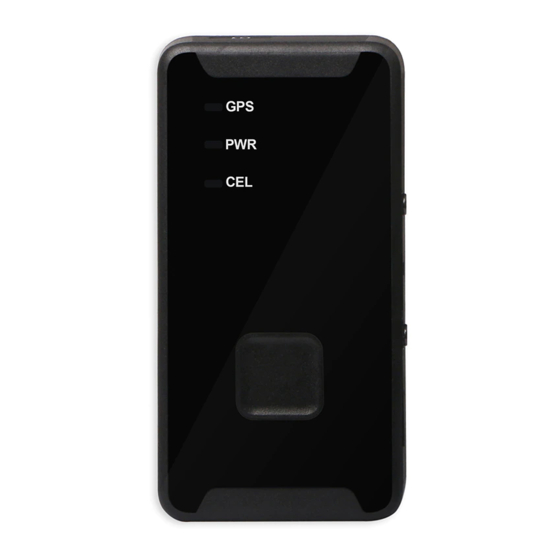
GL300W External Battery Kit User Manual 2. Product Overview 2.1. Appearance Figure 1: Appearance of GL300W EBK GL300WEBKUM001... -
Page 9: Parts List
All the components except the AC-DC charger will be put into the Pelican 1020 Waterproof Box. Frame for GL300W and The frame is used to fix the PCU and GL300W. AC-DC Charger AC-DC Charger is used to charger the external External Battery battery. -
Page 10: Pcu (Power Control Unit)
3. PCU (Power Control Unit) 3.1. Overview There are two connectors on the GL300W EBK: One is 4-pin connector for VBAT IN interface; the other is 8-pin connector for Digital Input and PWR Output interface. The PCU has an onboard motion sensor which can detect the motion/rest status of the PCU. -
Page 11: Interfaces
GL300W External Battery Kit User Manual 3.2. Interfaces 3.2.1. VBAT IN Interface The external battery should be connected to 4-pin connector which used as VABT IN interface of PCU. The pin description is shown in Table 4. Figure 3: VBAT IN Interface... -
Page 12: Digital Input Interface
GL300W External Battery Kit User Manual 3.2.2. Digital Input Interface Digital Input interface includes 2 digital inputs which can be used to monitor the external digital signal. They can be connected to toggle switch, tact switch or reed switch. There are four pins on the left side of the 8-pin connector. - Page 13 GL300W External Battery Kit User Manual The logical status of digital input 1 will effect on the power output of PCU. Please refer to chapter 3.6 for detail. The reference connection of digital input 1 is shown in following figure.
- Page 14 GL300W External Battery Kit User Manual The default logical status of digital input 2 is ‘0’ and it will be reversed when the electrical level of digital input 2 changes two times. The logical status of digital input 2 will effect on the power output of PCU. Please refer to chapter 3.6 for detail.
-
Page 15: Pwr Output Interface
The power output is included in the PWR Output interface. It also includes the UART interface for the communication between GL300W and PCU. There are four pins on the right side of the 8-pin connector. The pin description is shown in Table 6. -
Page 16: Sw101
GL300W External Battery Kit User Manual Figure 10: Toggle Switches 3.3.1. SW101 SW101 is used to enable/disable the onboard motion sensor. 3.3.2. SW102 SW102 is used to configure the auto power up function. If it is set to ‘L’, the power output will be enabled for at least 5 minutes every day even when the PCU is in rest. -
Page 17: Indication Led
Only when the logical status of digital input 1 and 2 are all 0, the power output can be disabled. PCU will send the report on every logical status change to the backend server via GL300W. Please refer to chapter 6.2 for detail. -
Page 18: External Battery
4. External Battery 4.1. Battery Specification The GL300W EBK includes a large capacity battery which can provide long standby time. The size of the battery is about 38mm * 80mm * 71mm. There are two connectors on the battery, one is for power output, and another is used for charging. -
Page 19: Pelican 1020 Box
GL300W External Battery Kit User Manual 5. Pelican 1020 BOX The GL300W EBK is included in a Pelican 1020 waterproof casing. It is designed following the IP67 standard which can provide protection for internal components. The dimension of this box is 16cm * 12cm * 6cm. -
Page 20: System Connection With Gl300W
GL300W External Battery Kit User Manual 6. System Connection With GL300W 6.1. Connection Overview The connection between external battery, PCU and GL300W is shown in following figure. Figure 13: Connection Overview GL300WEBKUM001 -19-... -
Page 21: Air Protocol Interface Relate To Pcu
6.2. Air Protocol Interface Relate to PCU 6.2.1. GTLSW If the PCU detects that the logical status of digit input 1 changes, it will send +RESP:GTLSW message to the backend server through GL300W. Table 9: +RESP:GTLSW Message Format Example: +RESP:GTLSW,1A0100,135790246811220,,0,1,0,4.3,92,70.0,121.354335,31.222073,200902140... -
Page 22: Gttsw
GL300W External Battery Kit User Manual 6.2.2. GTTSW The +RESP:GTTSW is used to indicate the logical status change of digital input 2. Table 10: +RESP:GTTSW Message Format Example: +RESP:GTTSW,1A0100,135790246811220,,1,0,0,4.3,92,70.0,121.354335,31.222073,200902140 13254,0460,0000,18d8,6141,00,20100214093254,11F0$ Parameter Length(byte) Range/format Default Protocol version XX0000 – XXFFFF, X∈{'A'-'Z','0'-'9'}... -
Page 23: Gtrst
GL300W External Battery Kit User Manual Table 11: +RESP:GTOMS Message Format Example: +RESP:GTOMS,1A0100,135790246811220,,1,0,0,4.3,92,70.0,121.354335,31.222073,20090214 013254,0460,0000,18d8,6141,00,20100214093254,11F0$ Parameter Length(byte) Range/format Default Protocol version XX0000 – XXFFFF, X∈{'A'-'Z','0'-'9'} Unique ID IMEI Device name Type State 0|1|3 GPS accuracy Speed <=5 0.0 – 999.9km/h Azimuth <=3... - Page 24 GL300W External Battery Kit User Manual Example: +RESP:GTRST,1A0100,135790246811220,,,,20100214093254,11F0$ Parameter Length (byte) Range/Format Default Protocol version XX0000 – XXFFFF, X∈{'A'-'Z','0'-'9'} Unique ID IMEI Device name Reserved Reserved Send time YYYYMMDDHHMMSS Count number 0000 – FFFF Tail character GL300WEBKUM001 -23-...
-
Page 25: Configuration Q&A
GL300W External Battery Kit User Manual 7. Configuration Q&A Question1: I am using the PCU. How can I configure the system to report when motion and stop reporting when rest? Answer: Please set the SW103 to ‘H’ and set the SW101 to ‘L’. The configuration on SW102 and SW104 is depending on your requirement.
Need help?
Do you have a question about the GL300W and is the answer not in the manual?
Questions and answers