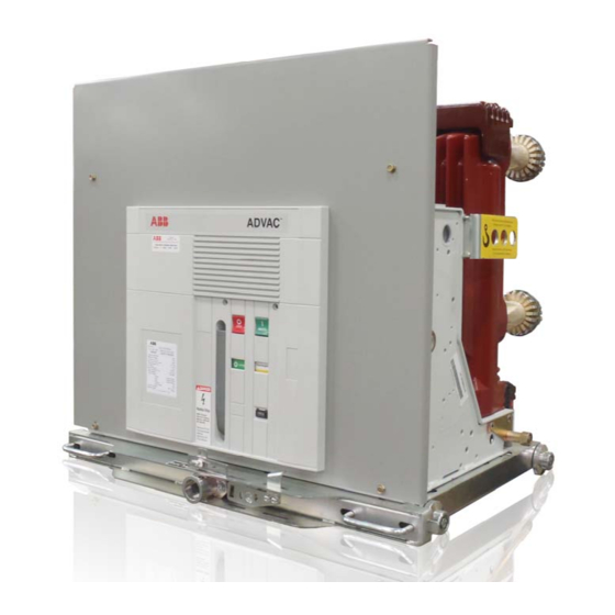
ABB ADVAC Installation And Operation Manual
Medium voltage vacuum circuit breaker
Hide thumbs
Also See for ADVAC:
- Installation & maintenance instructions manual (34 pages) ,
- Manual (23 pages) ,
- Installation & maintenance instructions manual (30 pages)

Related Manuals for ABB ADVAC


Summary of Contents for ABB ADVAC
- Page 1 ADVAC™ Medium Voltage Vacuum Circuit Breaker Installation and Operation Manual 1VAL050503-MB Rev B Replaces (1VAL057485-MB Rev. C) Oct 2013...
- Page 2 1VAL050503-MB Rev B Replaces (1VAL057485-MB Rev. C) Oct 2013...
-
Page 3: Table Of Contents
ABLE OF ONTENTS FORWARD ................................. 3 INTRODUCTION & SAFE PRACTICES ........................4 RECEIVING, HANDLING, & STORAGE ........................5 ACCESSORIES ................................6 Lifting Hook ..............................6 Racking Handle ............................7 INSERTION AND REMOVAL ............................ 7 Racking ..............................8-11 MECHANISM AND OPERATION ..........................12 Description of El Mechanism Twin and Single .................... -
Page 4: Forward
, ADVANCE , or abbreviated versions of ABB and OEM switchgear. It also contains plug-in primary and secondary disconnects with three physical ANSI operating positions within the cell: Disconnect, Test, and Connected. In the disconnected position there are no electrical connections. In the test position only, the secondary control wiring is connected via a patented disconnect mechanism which allows for remote testing of the breaker operations. -
Page 5: Introduction & Safe Practices
NTRODUCTION The purpose of this manual is to provide instructions for unpacking, storage, installation, operation and maintenance for the ADVAC™ vacuum circuit breakers. This manual should be carefully read and used as a guide during installation, initial operation, and maintenance. -
Page 6: Receiving, Handling, & Storage
If damage or indication of rough handling is evident, file a damage claim at once with the carrier and promptly notify the nearest District Office. ABB is not responsible for damage of goods after delivery to the carrier. -
Page 7: Accessories
ACCESSORIES IFTING The lifting hook is specifically designed for general lifting and lowering of the Vacuum circuit breaker, from shipping pallets or for lifting onto and off of work tables. The lifting hook is not designed to be used for insertion or removal of the circuit breaker from the switchgear compartment, instead, the use of an appropriate lift truck is required or serious dam- age to the breaker may occur. -
Page 8: Insertion And Removal
NOTE ABB has specific accessories to be used with ABB breakers. ALWAYS compare the breaker ratings nameplate with the switchgear ratings nameplate. Verify breaker secondary control voltage ratings are in agreement with the switchgear control voltage ratings. - Page 9 INSERTION AND REMOVAL CAUTION Use of any other racking device not approved by ABB will void the warranty!! Approved device shown NSERTION (Refer to [Figure 1] for compartment detail, [Appendix A] for breaker detail) 1. Open switchgear breaker compartment door [H] to its fully opened position.
-
Page 10: Racking
INSERTION AND REMOVAL ACKING ADVAC™ circuit breakers are designed with three positive racking positions. The Disconnect position allows only manual operation of the breaker without control power and with the shutters closed. The Test Position allows manual and electrical operation of the breaker with control power supplied through the secondary contacts with the shutters closed. - Page 11 INSERTION AND REMOVAL → D ISCONNECT 1. Perform visual inspection of the circuit breaker. a. Verify breaker is OPEN (push open button or initiate external electric trip if CLOSED). b. Verify switchgear breaker door is closed and secured. 2. Begin racking procedure using approved racking crank. a.
-
Page 12: Mechanism And Operation
MECHANISM AND OPERATION The EL operating mechanism of the Advac circuit breakers (in all versions) is fitted with a mechanical anti-pumping device which prevents re-closing due to either electrical or mechanical commands. Should both the closing command and any one of the opening commands (local or re- mote) be active at the same time, there would be a continuous succession of opening and closing operations. - Page 13 MECHANISM AND OPERATION Figure 2 Mechanism and Controls Open/Closed Auxiliary contacts Opening Pushbutton Closing Pushbutton Breaker Open/Closed Indicator NOT IN PICTUIRE OPENING Closing Spring Charge Indicator COIL (MO2) Closing Coil (MC) Opening Coil (MO) Spring charged Switch S1 (33Lsb) NOT IN PICTUIRE Under Voltage...
-
Page 14: Description Of El Operation
MECHANISM AND OPERATION Description of EL Operation The EL mechanism can be charged manually using the spring charging lever or electrically by the spring charging gear motor. While activat- ing one of the above mentioned methods, the cams (2) on the rotating operating shaft (1) move the closing lever assembly (3) to charge the closing spring. - Page 15 MECHANISM AND OPERATION Description of EL Operation Activating the closing push button rotates the closing shaft and releases the closing hook (1). The stored energy of the closing spring is transferred to the closing lever assembly (2) which pushes the long levers of the cam/ toggle assembly connected by a pin (3).
- Page 16 MECHANISM AND OPERATION Description of EL Operation The charging motor (if present) automati- cally rotates the operating mechanism. The closing spring is now charged again and ready for the next closing operation. Activating the opening push button rotates the opening shaft and releases the opening hook (1).
-
Page 17: Interlocks
MECHANISM AND OPERATION NTER OCKS The ADVAC™ breaker contains a number of interlocks. A description of each interlock follows as encountered during racking of the breaker into the breaker compartment. DANGER MODIFICATION TO INTERLOCKS CAN RESULT IN HAZARDOUS CONDITIONS TO PERSONNEL AND EQUIPMENT. -
Page 18: Manual Operation
MECHANISM AND OPERATION ANUAL PERATION The breaker can be operated manually or electrically. Refer to Basic Breaker Layout [Appendix A] for locations of indicators. Inspect initial state of the breaker to determine the operations available from Table 2. a. Closing Spring Charged/Discharged Indicator (6) b. -
Page 19: Electrical Operation
Optional test jumpers and test cabinets to connect control power to a withdrawn circuit breaker are available (contact the local ABB sales office for details). 1. Inspect initial state of the breaker to determine the operations available from Table 2 on previous page. -
Page 20: Control Scheme
ONTROL CHEME ADVAC™ circuit breakers are available with two control packages. The standard package (see Appendix D) includes charge (MS), close (MC), and open (MO) functions, and 4a and 4b auxiliary contacts for customer use. The optional package (see Appendix D) adds to the standard package 5a and 4b auxiliary contacts for customer use as well as an optional second open/trip coil (MO2) and/or under voltage (MU) open/trip device if required. - Page 21 MECHANISM AND OPERATION Control voltage available to charging motor Closing Spring Charged Close Signal Start of Closing Operation Close operation complete Closing spring discharged Opening spring charged Compression Springs charged Closing Spring Charged Start of Opening Operation Open operation complete Opening springs discharged Compression Springs discharged Charging Motor...
-
Page 22: Maintenance
MAINTENANCE AINTENANCE ADVAC™ circuit breakers are designed for a minimum amount of maintenance. Circuit breakers in a clean, non- corrosive environment require only annual inspection. Dusty or corrosive environments require inspection more often at the discretion of the user. Inspection is required following each interrupted fault. - Page 23 The maintenance operations must only be carried out by trained personnel and who follow all the safety regulations. Furthermore, it is advisable to call on ABB personnel, at least in cases for checking the performances in service and for repairs. Cut the power supply off and put the apparatus under safe conditions during the maintenance operations.
- Page 24 MAINTENANCE Stored energy operating mechanism Carry out the functional test of the operating mechanism after 5,000operations (2,000 operations for 3000 A circuit- breakers) or during ordinary maintenance operations Before doing the test, open the circuit-breaker and carry out the following operations In the case of with-drawable circuit-breakers, take the circuit breaker to the isolated area for test In the case of fixed circuit-breakers: cut off the power supply to the medium voltage circuit and follow proper lock-out tag out procedures as specified by the facility.
- Page 25 Should maintenance be carried out by the customer’s personnel, responsibility for the interventions remains with the customer. The replacement of parts not included in the “List of spare parts” must only be carried out by ABB personnel. In particular: – complete pole with bushings/connections –...
- Page 26 Charge Motor As- Closing spring sembly Note: Replacement of the EL Actuator (trip box) can only be carried out by ABB personnel or by specially skilled trained personnel, particularly for the necessary adjustments. 1VAL050503-MB Rev B Replaces (1VAL057485-MB Rev. C) Oct 2013...
-
Page 27: Truck
MAINTENANCE RUCK The truck requires visual inspection of hardware, lubrication and operations during routine maintenance. With the breaker outside the cell, verify all visible hardware tightness, including handles (9) and wheels (7). Wheels should rotate freely by hand movement. Replace or tighten any missing or loose hardware. With the breaker outside the cell, rotate the racking screw as though racking the breaker to the connect position. -
Page 28: Control Wiring
Lubrication on the primary contacts should be inspected during routine maintenance. Use NO-OX-ID special grade-A grease for the lubrication of primary contacts (ABB No. 713222A, 1 Pt. can). 1VAL050503-MB Rev B Replaces (1VAL057485-MB Rev. C) Oct 2013... - Page 29 MAINTENANCE CAUTION Applying abnormally high voltage across a pair of open contacts in vacuum may produce X-radiation. The radiation may increase with the increase in voltage and/or decrease in contact spacing. It is recommended that all operating personnel stand at least one meter away and in front of the circuit breaker during testing.
-
Page 30: Appendices
APPENDICES APPENDIX A BASIC BREAKER LAYOUT All ADVAC breakers have the same basic layout regardless of rating or pole configuration. Description FRONT PLATE ASSEMBLY CLOSE PUSH BUTTON OPEN PUSH BUTTON CLOSE/OPEN INDICATOR CHARGING HANDLE CHARGED/DISCHARGED INDICATOR RACKING SCREW COLLAR POSITION RELEASE LEVER... -
Page 31: Appendix B: Basic Breaker Dimensions And Weights
APPENDIX B BASIC BREAKER DIMENSIONS AND WEIGHTS All ADVAC breakers of this style have the same basic dimensions (i.e. pole spacing, mounting locations) regardless of pole configuration. Hole patterns do change dependent upon the amperage capacity of the breaker. 1VAL050503-MB Rev B Replaces (1VAL057485-MB Rev. C) Oct 2013... - Page 32 APPENDIX B BASIC BREAKER DIMENSIONS AND WEIGHTS All ADVAC breakers of this style have the same basic dimensions (i.e. pole spacing, mounting locations) regardless of pole configuration. Hole patterns do change dependent upon the amperage capacity of the breaker. 1VAL050503-MB Rev B Replaces (1VAL057485-MB Rev. C) Oct 2013...
- Page 33 APPENDIX B BASIC BREAKER DIMENSIONS AND WEIGHTS All ADVAC breakers of this style have the same basic dimensions (i.e. pole spacing, mounting locations) regardless of pole configuration. Hole patterns do change dependent upon the amperage capacity of the breaker. 1VAL050503-MB Rev B Replaces (1VAL057485-MB Rev. C) Oct 2013...
- Page 34 APPENDIX B BASIC BREAKER DIMENSIONS AND WEIGHTS All ADVAC breakers of this style have the same basic dimensions (i.e. pole spacing, mounting locations) regardless of pole configuration. Hole patterns do change dependent upon the amperage capacity of the breaker. 1VAL050503-MB Rev B Replaces (1VAL057485-MB Rev. C) Oct 2013...
- Page 35 APPENDIX B BASIC BREAKER DIMENSIONS AND WEIGHTS All ADVAC breakers of this style have the same basic dimensions (i.e. pole spacing, mounting locations) regardless of pole configuration. Hole patterns do change dependent upon the amperage capacity of the breaker. 1VAL050503-MB Rev B Replaces (1VAL057485-MB Rev. C) Oct 2013...
- Page 36 APPENDIX B BASIC BREAKER DIMENSIONS AND WEIGHTS All ADVAC breakers of this style have the same basic dimensions (i.e. pole spacing, mounting locations) regardless of pole configuration. Hole patterns do change dependent upon the amperage capacity of the breaker. 1VAL050503-MB Rev B Replaces (1VAL057485-MB Rev. C) Oct 2013...
- Page 37 APPENDIX B BASIC BREAKER DIMENSIONS AND WEIGHTS All ADVAC breakers of this style have the same basic dimensions (i.e. pole spacing, mounting locations) regardless of pole configuration. Hole patterns do change dependent upon the amperage capacity of the breaker. 1VAL050503-MB Rev B Replaces (1VAL057485-MB Rev. C) Oct 2013...
- Page 38 APPENDIX B BASIC BREAKER DIMENSIONS AND WEIGHTS All ADVAC breakers of this style have the same basic dimensions (i.e. pole spacing, mounting locations) regardless of pole configuration. Hole patterns do change dependent upon the amperage capacity of the breaker. TYPE...
- Page 39 APPENDIX B BASIC BREAKER DIMENSIONS AND WEIGHTS All ADVAC breakers of this style have the same basic dimensions (i.e. pole spacing, mounting locations) regardless of pole configuration. Hole patterns do change dependent upon the amperage capacity of the breaker. TYPE...
-
Page 40: Appendix D: Wiring Diagrams
APPENDICES APPENDIX D TYPICAL SCHEMATIC & WIRING DIAGRAMS TANDARD IRING The schematic shows the basic wiring scheme for a breaker with single secondary wiring. This wiring includes four “a” and three “b” auxiliary contacts. The point-to-point diagram shows the physical connections and wire numbers used in the wiring harness. - Page 41 APPENDICES APPENDIX D TYPICAL SCHEMATIC & WIRING DIAGRAMS TANDARD IRING The schematic shows the basic wiring scheme for a breaker with single secondary wiring. This wiring includes four “a” and three “b” auxiliary contacts. The point-to-point diagram shows the physical connections and wire numbers used in the wiring harness.
- Page 42 APPENDICES APPENDIX D TYPICAL SCHEMATIC & WIRING DIAGRAMS ECONDARY IRING The schematic shows the basic wiring scheme for a breaker with optional wiring. This wiring includes nine “a” and seven“b” auxiliary contacts. The point-to-point diagram shows the physical connections and wire numbers used in the wiring harness.
- Page 43 APPENDICES APPENDIX D TYPICAL SCHEMATIC & WIRING DIAGRAMS MECH The schematic shows the basic wiring scheme for the twin EL breaker with optional wiring. This wiring includes nine “a” and seven “b” auxiliary contacts. The point-to-point diagram shows the physical connections and wire numbers used in the wiring harness.
- Page 44 APPENDICES APPENDIX D TYPICAL SCHEMATIC & WIRING DIAGRAMS ECONDARY IRING The schematic shows the basic wiring scheme for a breaker with optional wiring. This wiring includes nine “a” and seven “b” auxiliary contacts. The point-to-point diagram shows the physical connections and wire numbers used in the wiring harness.
-
Page 45: Appendix E: Charging Motor And Coil Data
APPENDIX E APPENDIX E Charging motor and Coil data 1VAL050503-MB Rev B Replaces (1VAL057485-MB Rev. C) Oct 2013... - Page 46 APPENDIX E APPENDIX E Charging motor and Coil data 1VAL050503-MB Rev B Replaces (1VAL057485-MB Rev. C) Oct 2013...
- Page 47 APPENDIX E APPENDIX E Auxiliary contact data 1VAL050503-MB Rev B Replaces (1VAL057485-MB Rev. C) Oct 2013...
- Page 48 APPENDIX G 1VAL050503-MB Rev B Replaces (1VAL057485-MB Rev. C) Oct 2013...
-
Page 49: Product Quality And Enviromental Protection
Product Quality and Environmental Protection ABB products are manufactured to meet or exceed the standards of compliance for quality and environmental manage- ment systems in accordance with ISO 9001 and ISO 14 001. All of these items can be supplied with a certificate of quali- ty upon request. - Page 50 1VAL050503-MB Rev B Replaces (1VAL057485-MB Rev. C) Oct 2013...
- Page 51 Customer service +1 800 929 7947 ext. 5 © Copyright 2011 ABB Inc. All rights reserved. +1 407 732 2000 ext. 2510 E-Mail: customer.service.group@us.abb.com www.abb.com/mediumvoltage 1VAL050503-MB Rev B Replaces (1VAL057485-MB Rev. C) Oct 2013...
Need help?
Do you have a question about the ADVAC and is the answer not in the manual?
Questions and answers