Table of Contents
Advertisement
Quick Links
Advertisement
Table of Contents

Related Manuals for Columbus Instruments CLAMS


Summary of Contents for Columbus Instruments CLAMS
- Page 1 CLAMS Hardware Manual June 1, 2022 1012-0001 v1.01 950 North Hague Avenue Phone: (614) 276-0861 Columbus, Ohio 43204-2121 USA Fax: (614) 276-0529 Sales: sales@colinst.com Toll Free: 1-800-669-5011 Service: service@colinst.com http://www.colinst.com...
-
Page 3: Table Of Contents
CLAMS Hardware Manual 1012-0001 v1.01 Table of Contents 1 – Introduction ............................... 5 1.1 Overview ............................... 5 1.2 Electrical Components ..........................5 1.2.1 AC Power ..............................5 1.2.2 DC Coaxial Connection ........................... 5 1.2.3 Ethernet Cable Connection ........................6 1.3 Air and Water Connections ........................... 6 1.3.1 Nut and Ferrule Fittings ......................... - Page 4 CLAMS Hardware Manual 1012-0001 v1.01 3.5.1 Paramagnetic Oxygen Sensor Specifications ..................34 3.6 Chemical Oxygen Sensor Setup ........................36 3.6.1 Placing the Components ........................36 3.6.2 Connecting the Components........................ 38 3.7 Zirconia Oxygen Sensor Setup ........................45 3.7.1 Placing the Components ........................45 3.7.2 Connecting the Components........................
-
Page 5: Introduction
32 subjects. All the data collection components of CLAMS connect by the way of the “CI-Bus” technology system. The CI-Bus easily integrates all the data from all devices for collection by the host computer. Configuration options within each system allow around-the-clock, automated, non-invasive collection of physiological and behavioral parameters such as activity, food and water consumption, metabolic performance, temperature, etc. -
Page 6: Ethernet Cable Connection
The Ethernet cable connection is used for CI-Bus communication and other electrical connections between various components of the CLAMS system. It is an 8-pin, 8-conductor, plug to plug cable commonly referred as: RJ-45, CAT5, CAT5e, network cables, etc. They are found between all the CI-Bus devices and the Optical Activity sensors. -
Page 7: Nut And Ferrule Fittings
CLAMS Hardware Manual 1012-0001 v1.01 1.3.1 Nut and Ferrule Fittings A nut and ferrule are used to make an air-tight or water-tight connection. These connections are commonly found between calorimetry and drinking components of the system and cages. • To make a new nut and ferrule connection: trim the end of the plastic tube with a sharp implement (tube cutter preferred) leaving the end as square as possible. -
Page 8: Quick-Connect Fittings With Lock
CLAMS Hardware Manual 1012-0001 v1.01 • To remove the tube from the connector, press and hold the locking collar against the body of the fitting. • Now pull the tube free from the fitting. 1.3.3 Quick-Connect Fittings with Lock Quick-connect fittings with lock are used to make air-tight connections to sources which require intermittent use. -
Page 9: Computer Setup
Serial Bus (USB) port. 2.2 CI-Bus Hub/Switch Mini The CI-Bus Hub is used to create the interface between the host computer and the CLAMS/Oxymax system. It connects via a USB port which creates a virtual COM port accessible by the Oxymax software. All... - Page 10 CLAMS Hardware Manual 1012-0001 v1.01 communications from the Oxymax software are passed through the CI-Bus Hub to four (4) terminated CI-Bus ports. By “daisy-chain” fashion, ethernet cables are used to connect devices to the CI-Bus. The following details the indicators and ports found on the CI-Bus Hub: •...
-
Page 11: Connecting The Ci-Bus Hub
CLAMS Hardware Manual 1012-0001 v1.01 2.3 Connecting the CI-Bus Hub As the CI-Bus Hub is a USB connected device, it is placed locally near the host computer. You will also need the following:... -
Page 12: Oxymax
CLAMS Hardware Manual 1012-0001 v1.01 1 x USB A-B cable Using the USB A-B cable, insert the A plug into a free USB port on the host computer. Insert the B plug into the USB port on the CI-Bus Hub. When properly connected, the power indicator should light. - Page 13 CLAMS Hardware Manual 1012-0001 v1.01 Negative ventilation provides many advantages: • Small leaks around the openings in the cage lid have a minimal effect upon respiratory gas concentrations because the intended fresh air is drawn from the immediate atmosphere around the cage.
-
Page 14: Universal Flow Controller
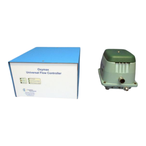
CLAMS Hardware Manual 1012-0001 v1.01 3.1.2 Universal Flow Controller The Universal Flow Controller (UFC) provides ventilation for eight cages and one reference cage. It also selects one of the air supply lines (channels) for gas sampling. The UFC requires an external ventilation pump, matched in size for the required ventilation rate of all channels. - Page 15 CLAMS Hardware Manual 1012-0001 v1.01 Universal Flow Controller Indicators and Ports • Power – A green light which indicates connection to a source of DC power. • Data In - A yellow light which indicates the host computer is transmitting data.
-
Page 16: Ventilation Pump
CLAMS Hardware Manual 1012-0001 v1.01 • CH [1:8] & Ref – The ports for connection of the particle-filtered and restricted 1/4" air supply lines from each cage in the system plus the reference cage. • Test Out – The output port for gas sampling. -
Page 17: Connecting Components
CLAMS Hardware Manual 1012-0001 v1.01 • Vacuum Port - The vacuum source, provided by a push-fit fitting situated in the middle of the left side of the pump. • Pressure Port - The exhaust port, provided by a 3/4" NPT MIP situated on bottom corner of the left side of the pump. - Page 18 CLAMS Hardware Manual 1012-0001 v1.01 You will also need the following: 2 x AC outlets from a common-switched source 1 x suitable 12V coaxial DC power supply with AC power cord 1 x ethernet cable 1 x filter assembly for the ventilation pump ...
- Page 19 CLAMS Hardware Manual 1012-0001 v1.01 For each group of cages with UFC and ventilation pump: • Using an appropriate length of 1/4" green air line, connect each port (Ch[1:8] and Ref) to its associated cage’s air supply 1/4" union (at the end of the cage restrictor assembly).
- Page 20 CLAMS Hardware Manual 1012-0001 v1.01 For proper operation, all channel and reference ports require a particle filter and system specific flow restrictor. • Using an appropriate length of 1/2" natural air line, connect the vacuum port of the Ventilation Pump to the “Gas Supply”...
-
Page 21: Gas Sensor Chain Setup
CLAMS Hardware Manual 1012-0001 v1.01 • Using the 12V power supply, connect the DC coaxial plug into the “12V ⎓ 3A” coaxial power jack of the UFC. • Using an AC power cord, connect the 12V power supply to a switched AC power source. -
Page 22: Universal Gas Conditioner
CLAMS Hardware Manual 1012-0001 v1.01 schematic of the two most common components of the gas sensor chain: the Universal Gas Conditioner (UGC) and the Chemical Oxygen (O2) sensor. 3.2.2 Universal Gas Conditioner The Universal Gas Conditioner (UGC) combines the functions of prior sub-systems and components into one comprehensive unit. - Page 23 CLAMS Hardware Manual 1012-0001 v1.01 1. Power – A green light which indicates connection to a source of DC power. 2. Data In - A yellow light which indicates the host computer is transmitting data. 3. Data Out – A blue light which indicates the UGC is transmitting data.
- Page 24 CLAMS Hardware Manual 1012-0001 v1.01 1. Sample – The input port for an ammonia-trapped and particle-filtered sample from a Universal Flow Controller’s selected “Test Out” port. 2. Reference – The input port for a particle-filtered sample from the room air reference (typically the same source provided to the cages).
-
Page 25: Filter Columns
CLAMS Hardware Manual 1012-0001 v1.01 14. Rx – An indicator (typically yellow) on the bottom right corner which indicates the UGC is transmitting data. 15. 12VDC ⎓ 2A – DC coaxial jack for connection to a suitable power supply. 16. Analog Input – A 25-pin female D-SUB connector for future expansion and connection to various sensors. -
Page 26: Ammonia Traps
CLAMS Hardware Manual 1012-0001 v1.01 Zirconia Oxygen Sensors are employed, one column of soda lime is provided and should be replaced (in the same manner as Drierite) every five years for uninterrupted service. Filter Media Replacement Both Drierite and Soda Lime are hazardous substances. They can release nuisance dust in handling or during use. -
Page 27: Particle Filters
CLAMS Hardware Manual 1012-0001 v1.01 are placed in series ahead of a particle filter in the sample line and all together are called the “Sample Line Filter Assembly”. Ammonia Trap Replacement Observe the second (middle) ammonia trap in the assembly. When a color change (from blue to ‘wet’ dark blue/aqua green) is noted, then the first ammonia trap is completely exhausted. -
Page 28: Chemical Oxygen Sensor
CLAMS Hardware Manual 1012-0001 v1.01 3.3 Chemical Oxygen Sensor The Chemical Oxygen Sensor is used to measure the concentration of oxygen present in the gas sample as a percentage. Sensing is performed by an electrochemical cell. Sample air diffuses through a membrane on the end of the cell which drives a chemical reaction, which generates a voltage. - Page 29 CLAMS Hardware Manual 1012-0001 v1.01 FLASH: The sample temperature is moving toward it’s respective operating setpoint. ON: The sample temperature is steady and reports valid measurements. 5. Sensor Fault – A red light which indicates the status of the sample heater circuitry.
-
Page 30: Chemical Oxygen Sensor Replacement
CLAMS Hardware Manual 1012-0001 v1.01 3.3.2 Chemical Oxygen Sensor Replacement When necessary, use the following procedure to replace the chemical oxygen sensor. • Access the sensor compartment by pressing the blue dot labeled “Press Here to Open” on the front panel of the cabinet. -
Page 31: Zirconia Oxygen Sensor
The sensing element is consumable, which should be replaced every four years to provide uninterrupted service. It has a high rate of data throughput which can produce accurate results every twenty seconds per cage. This sensor is commonly employed in large, multi-channel CLAMS and Oxymax systems. - Page 32 CLAMS Hardware Manual 1012-0001 v1.01 1. Power – A green light which indicates connection to a source of DC power. 2. Data In – A yellow light which indicates the host computer is transmitting data. 3. Data Out – A blue light which indicates the Oxygen Sensor is transmitting data.
- Page 33 CLAMS Hardware Manual 1012-0001 v1.01 1. Sample Supply – The input port for connection from the UGC’s Sample Supply port. 2. Sample Return – The output port for connection to the next gas sensor or to the UGC’s “Sample Return” port.
-
Page 34: Paramagnetic Oxygen Sensor
CLAMS Hardware Manual 1012-0001 v1.01 3.5 Paramagnetic Oxygen Sensor The Paramagnetic Oxygen Sensor is used to measure the concentration of oxygen present in the gas sample as a percentage. Sensing is performed by a glass dumbbell assembly suspended in a magnetic field which twists when exposed to oxygen. - Page 35 CLAMS Hardware Manual 1012-0001 v1.01 1. Power – A green light which indicates connection to a source of DC power. 2. Data In – A yellow light which indicates the host computer is transmitting data. 3. Data Out – A blue light which indicates the Oxygen Sensor is transmitting data.
-
Page 36: Chemical Oxygen Sensor Setup
The components are best placed as follows from the right (the side edge of the working surface) to the left: Filter Columns, Universal Gas Conditioner, and the Chemical Oxygen Sensor. Each CLAMS/Oxymax system ships with a detailed schematic drawing detailing the expected connections for that system. Typically, the color of each port indicates the typical color of tubing for connection. - Page 37 CLAMS Hardware Manual 1012-0001 v1.01 You will also need the following: 1 x 12VDC power supply with AC power cord for the Universal Gas Conditioner 1 x 24VDC power supply with AC power cord for the Chemical Oxygen Sensor ...
-
Page 38: Connecting The Components
CLAMS Hardware Manual 1012-0001 v1.01 3.6.2 Connecting the Components Assembling the Dehumidifier • Locate the Dehumidifier Supply Filter Assembly. It consists of a Parker/Balston filter with a 1/4” union connector over each end and a short section of 1/4” blue air line connected to the down-stream port. - Page 39 CLAMS Hardware Manual 1012-0001 v1.01 • Connect the 1/4” blue air line of the Dehumidifier Supply Filter Assembly to the “Dehumidifier Supply” port of the UGC. • Using an appropriate length of the 1/4” blue air line, connect the filter end to the bottom port of the Drierite column.
- Page 40 CLAMS Hardware Manual 1012-0001 v1.01 Assembling the Reference Source • Locate the Reference Filter Assembly. It consists of a Parker/Balston particle filter with a black 1/4” to 1/8” reducing union and a short length of 1/8” blue tubing. • Fully insert the free end of the 1/8” blue tube into the Input “Reference” port of the UGC.
- Page 41 CLAMS Hardware Manual 1012-0001 v1.01 • Position the assembly near the UGC and use an appropriate length of 1/8” red air line to connect the down-stream port of the filter (the end with the particle filter) to the “Sample” port of the UGC.
- Page 42 CLAMS Hardware Manual 1012-0001 v1.01 • Using an appropriate length of the 1/4” natural air line, connect the filter end to the bottom port of the Soda Lime column. The top port is open to room air. Assembling the Span Gas Source •...
- Page 43 CLAMS Hardware Manual 1012-0001 v1.01 Assembling the Exhaust Ports • Locate the Exhaust Port Filter Assembly. It consists of a 1/4” tee fitting already connected with short lengths of red and blue air line and a Parker/Balston particle filter. •...
- Page 44 CLAMS Hardware Manual 1012-0001 v1.01 Sensor Sample Tubing Connections • Using an appropriate length of 1/8” red air line, connect the output “Sample Supply” port of the UGC to the input “Sample Supply” port of the Oxygen Sensor. • Using an appropriate length of 1/8 red air line, connect the output “Sample Return”...
-
Page 45: Zirconia Oxygen Sensor Setup
The components are best placed as follows from the right (the side edge of the working surface) to the left: Filter Columns, Universal Gas Conditioner, and the Zirconia Oxygen Sensor. Each CLAMS/Oxymax system ships with a detailed schematic drawing detailing the expected connections for that system. Typically, the color of each port indicates the typical color of tubing for connection. - Page 46 CLAMS Hardware Manual 1012-0001 v1.01 You will also need the following: 1 x 12VDC power supply with AC power cord for the Universal Gas Conditioner 1 x 24VDC power supply with AC power cord for the Zirconia Oxygen Sensor ...
-
Page 47: Connecting The Components
CLAMS Hardware Manual 1012-0001 v1.01 3.7.2 Connecting the Components Assembling the Dehumidifier • Locate the Dehumidifier Supply Filter Assembly. It consists of a Parker/Balston filter with a 1/4" union connector over each end and a short section of 1/4" blue air line connected to the down-... - Page 48 CLAMS Hardware Manual 1012-0001 v1.01 • Connect the 1/4" blue air line of the Dehumidifier Supply Filter Assembly to the “Dehumidifier Supply” port of the UGC. • Using an appropriate length of 1/4" blue air line, connect the filter end to the bottom port of the Drierite column.
- Page 49 CLAMS Hardware Manual 1012-0001 v1.01 Assembling the Reference Source • Using an appropriate length of 1/8” blue air line, connect the source of reference gas (typically from a tee fitting placed in the air supply line of the Reference Cage) to the Input “Reference” port of the UGC.
- Page 50 CLAMS Hardware Manual 1012-0001 v1.01 Assembling the Zero Gas Source • Locate the Zero Gas Filter Assembly. It consists of a Parker/Balston filter with a 1/4" union connector over each end and a short section of 1/4" natural air line connected to the down-stream port.
- Page 51 CLAMS Hardware Manual 1012-0001 v1.01 • Connect the free end of the air line to the “Span Gas” port of the UGC. • Form the length of the air line into a coil and store in a non-obtrusive location. Assembling the Exhaust Ports •...
- Page 52 CLAMS Hardware Manual 1012-0001 v1.01 Sensor Sample Tubing Connections • Using an appropriate length of 1/8” red air line, connect the output “Sample Supply” port of the UGC to the input “Sample Supply” port of the Oxygen Sensor. • Using an appropriate length of 1/8” red air line, connect the output “Sample Return” port of the Oxygen Sensor to the input “Sample Return”...
- Page 53 CLAMS Hardware Manual 1012-0001 v1.01 • Using an appropriate length of 1/8” blue air line, connect the output “Reference Return” port of the Oxygen Sensor to the “Sample Return” port of the UGC. Electrical Power Connections Using the 24V power supply, connect the DC coaxial plug into the “24V ⎓ 2.7A” coaxial power jack of •...
-
Page 54: Paramagnetic Oxygen Sensor Setup
The components are best placed as follows from the right (the side edge of the working surface) to the left: Filter Columns, Universal Gas Conditioner, and the Paramagnetic Oxygen Sensor. Each CLAMS/Oxymax system ships with a detailed schematic drawing detailing the expected connections for that system. Typically, the color of each port indicates the typical color of tubing for connection. - Page 55 CLAMS Hardware Manual 1012-0001 v1.01 You will also need the following: 1 x 12VDC power supply with AC power cord for the Universal Gas Conditioner 1 x 24VDC power supply with AC power cord for the Paramagnetic Oxygen Sensor ...
-
Page 56: Connecting The Components
CLAMS Hardware Manual 1012-0001 v1.01 3.8.2 Connecting the Components Assembling the Dehumidifier • Locate the Dehumidifier Supply Filter Assembly. It consists of a Parker/Balston filter with a 1/4" union connector over each end and a short section of 1/4" blue air line connected to the down-stream port. - Page 57 CLAMS Hardware Manual 1012-0001 v1.01 • Connect the 1/4" blue air line of the Dehumidifier Supply Filter Assembly to the “Dehumidifier Supply” port of the UGC. • Using an appropriate length of 1/4" blue air line, connect the filter end to the bottom port of the Drierite column.
- Page 58 CLAMS Hardware Manual 1012-0001 v1.01 Assembling the Reference Source • Locate the Reference Filter Assembly. It consists of a Parker/Balston particle filter with a black 1/4" to 1/8” reducing union and a short length of 1/8” blue tubing. • Fully insert the free end of the 1/8" blue tube into the Input “Reference” port of the UGC.
- Page 59 CLAMS Hardware Manual 1012-0001 v1.01 • Position the assembly near the UGC and use an appropriate length of 1/8” red air line to connect the down-stream port of the filter (the end with the particle filter) to the “Sample” port of the UGC.
- Page 60 CLAMS Hardware Manual 1012-0001 v1.01 • Form the length of the air line into a coil and store in a non-obtrusive location. Assembling the Span Gas Source • Locate the Span Gas Supply Assembly. It consists of 6 meters (20 feet) or more of yellow 1/4" air line joining with a male quick-connect fitting plug and a yellow ruby restrictor.
- Page 61 CLAMS Hardware Manual 1012-0001 v1.01 • Fully insert the free end of the 1/4" blue tube into the “Reference Exhaust” port of the UGC. • Then fully insert the free end of the 1/4" red tube into the “Sample Exhaust” port of the UGC. The filter should now be positioned horizontally, projecting away from the UGC.
- Page 62 CLAMS Hardware Manual 1012-0001 v1.01 • Using an appropriate length of 1/8” red air line, connect the output “Sample Return” port of the Oxygen Sensor to the input “Sample Return” port of the UGC. Electrical Power Connections Using the 24V power supply, connect the DC coaxial plug into the “24V ⎓ 2.7A” coaxial power jack of •...
-
Page 63: Feeding
2 Mass Scale The mass scale is usually integrated into the CLAMS shelf. The user needs to only switch on the scale after power has been applied to the shelf. The following details the ports and buttons found on the mass scale. The... -
Page 64: Connecting The Mass Scale
4. Menu – Not used. 1. RS232 – A serial port used for communication that connects to the serial port of the CLAMS shelf. 2. Power Supply – A coaxial DC power jack used to supply power to the scale. - Page 65 1 x coaxial DC plug-plug cable 0.4m in length The following photo shows the relative position of the mass scales (two are on the left) and the CLAMS interface board (one on the rights) that will connect from underneath the CLAMS shelf. The connecting cables must pass through a structural support with obround cutouts (Left of center).
-
Page 66: Load Cells
CLAMS Hardware Manual 1012-0001 v1.01 • Using the coaxial DC cable, connect the labeled “12 VDC” port “Scale 12 VDC” of the CLAMS interface board to the “Power Supply” port of the mass scale. Again, be sure to pass the cable through the obround cutout as shown. -
Page 67: Feeder Assembly
CLAMS Hardware Manual 1012-0001 v1.01 Do not tamper with load cell food tray holder or anchor assemblies. Under no circumstances should the bolt and locknut be adjusted. This risks irreparable damage to the load cell. If load cell and feeder assemblies require adjustment, contact Columbus Instruments. -
Page 68: Assembling The Feeder
CLAMS Hardware Manual 1012-0001 v1.01 Also, two tools are provided: A wrench for removing the hopper from the food bowl A rod for assembling the components of the feeder assembly and for loading the food into the hopper The hopper is designed to deliver powdered food. - Page 69 CLAMS Hardware Manual 1012-0001 v1.01 • Fully insert the hopper with push plate into the hole at the end of the rod until the rod and metal tube of the push plate touch as shown. • While keeping the rod fully inserted into the hopper, bring the two halves of the feeder assembly together compressing the spring.
-
Page 70: Filling The Feeder With Food
CLAMS Hardware Manual 1012-0001 v1.01 Shows mouse (left) and rat (right) feeder 4.4.2 Filling the Feeder with Food The mouse and rat feeders can hold approximately 76 and 146 cubic centimeters of powdered food, respectively. You will need the rod used for assembly and it is recommended to use a paper cup for pouring the powdered food into the hopper. -
Page 71: Disassembling The Feeder Assembly
CLAMS Hardware Manual 1012-0001 v1.01 • Pour the powdered food through the screen and into the hopper until full. • Now remove the rod and tap the feeder on the table. The spring and push plate will raise the food up to the screen and fill any free space. -
Page 72: Cleaning
The compressed spring will forcefully push the hopper free from the bowl. To avoid damage, do not drop the hopper while opening. 5 – Cleaning Columbus Instruments employs several materials in the fabrication of CLAMS cages: Polycarbonate Plastic Acrylic Plastic Polyvinylchloride Plastic (PVC) Some materials tolerate aggressive cleaning agents and methods while others require special handling. - Page 73 CLAMS Hardware Manual 1012-0001 v1.01 ✓ DO machine wash ✓ DO employ a dilute (10%) bleach solution ✓ DO expose to temperatures less than 80°C ✓ DO employ mild acetic acid DO NOT employ ammonia or alcohol DO NOT expose to temperatures above 80°C ...
- Page 74 CLAMS Hardware Manual 1012-0001 v1.01 The components shown below is manufactured from Mixed Materials: ✓ DO clean (especially tip) prior to experiment ✓ DO hand wash with soapy water ✓ DO employ a dilute (10%) bleach solution ✓ DO expose to temperatures less than 45°C ✓...
Need help?
Do you have a question about the CLAMS and is the answer not in the manual?
Questions and answers