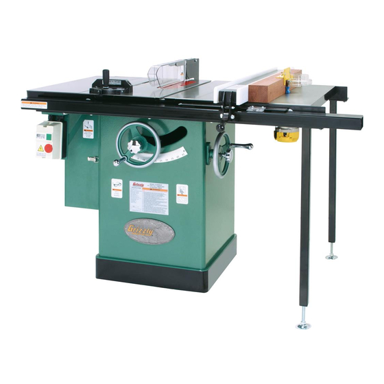
Grizzly G1023SLW Instruction Sheet
Router guard kit
Hide thumbs
Also See for G1023SLW:
- Owner's manual (72 pages) ,
- Parts manual (10 pages) ,
- Owner's manual (72 pages)
Advertisement
Quick Links
Download this manual
See also:
Owner's Manual
A router guard kit is included with your machine to
reduce the risk of accidental cutter contact during
operation. The router guard is also designed to be
connected to a dust collector to help collect dust
and chips during operation.
The router guard is intended to be used with a
shop-made fence and must be used when mak-
ing cuts that leave part of the router bit exposed
to the operator.
Inventory & Assembly
The inventory is shown in Figure 1 and the parts
breakdown and assembly lines are shown in
Figure 2.
REF PART #
DESCRIPTION
1
PS25
PHLP HD SCR 8-32 X 5/8
2
PWN02
WING NUT 1/4-20
3
PHTEK11
WOOD SCREW #8 X 3/4
4
P1023SLW620-4
HORIZONTAL BRACKET
5
P1023SLW620-5
VERTICAL BRACKET
6
PCB18
CARRIAGE BOLT 1/4-20 X 1/2 2
7
P1023SLW620-7
GUARD
8
PW08
FLAT WASHER #8
9
P1023SLW620-9
LOCK WASHER #8
10
PN14
HEX NUT 8-32
11
P1023SLW620-11 PHLP HD SCR 10-24 X 2-1/2
12
PW06
FLAT WASHER 1/4
Overtightening the fasteners that secure the
plastic guard to the bracket may crack or
break the plastic guard, rendering it unsafe
for use.
If you need help with the router guard, call our
Tech Support at: (570) 546-9663.
WARNING: NO PORTION OF THIS DOCUMENT MAY BE REPRODUCED IN ANY SHAPE
OR FORM WITHOUT THE WRITTEN APPROVAL OF GRIZZLY INDUSTRIAL, INC.
QTY
2
2
2
1
1
1
6
2
2
4
2
COPYRIGHT © APRIL, 2006 BY GRIZZLY INDUSTRIAL, INC.
#TR8217 PRINTED IN TAIWAN
ROUTER GUARD KIT
FOR G1023SLW
INSTRUCTION SHEET
Router guard inventory.
Figure 1.
�
�
�
�
�
Parts breakdown.
Figure 2.
�
��
�
�
�
�
��
�
��
Advertisement

Summary of Contents for Grizzly G1023SLW
- Page 1 Tech Support at: (570) 546-9663. COPYRIGHT © APRIL, 2006 BY GRIZZLY INDUSTRIAL, INC. WARNING: NO PORTION OF THIS DOCUMENT MAY BE REPRODUCED IN ANY SHAPE OR FORM WITHOUT THE WRITTEN APPROVAL OF GRIZZLY INDUSTRIAL, INC. ROUTER GUARD KIT FOR G1023SLW INSTRUCTION SHEET Figure 1.
-
Page 2: Fence Setup
� ��� Figure 3. Support board dimensions. Move the table saw fence next to the opening on the router table extension wing and mark the center point of the table hole opening on the right-hand side of the table saw fence face (Figure 4). - Page 3 Unclamp the support board and fence face, and drill holes through the support board where marked with a ⁄ Countersink the holes in the face of the sup- port board approximately drill bit, as shown in Figure 7. �������� ���� ����...
- Page 4 15. Mount the table saw fence to the left of the router bit and move the fence so the support board is next to the router bit.
- Page 5 17. Clamp, predrill with a countersinking bit, and attach the fence pieces with at least two wood screws per side, as shown in Figure 15. (Only use wood screws that are long enough to thread into the support board, but not too long that they enter the plastic fence face.) Note: If you followed Step 13, be sure to...


Need help?
Do you have a question about the G1023SLW and is the answer not in the manual?
Questions and answers