Table of Contents
Advertisement
Advertisement
Table of Contents

Related Manuals for Humboldt HM-5030


Summary of Contents for Humboldt HM-5030
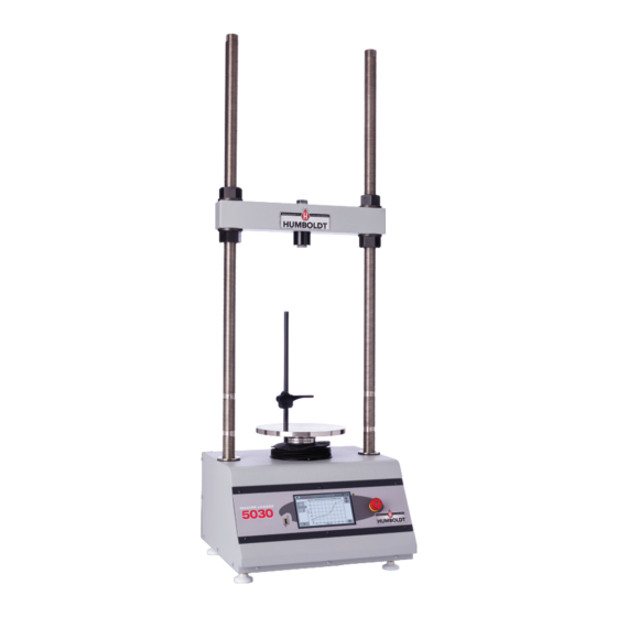
- Page 1 HM-5030 product manual 08.16 Master Loader Load Frame...
-
Page 2: Table Of Contents
Contents Introduction Touch-Screen Controller provides: Humboldt's NEXT software provides: Load Frame Specifications Controller Specifications General Warnings Safety Warnings Electrical Warnings Manufacturer's Rights and Responsibilities Software Copyright Important Notice Updated Products Fitness for Application Unpacking Quick Start Guide Startup Scenarios Electrical Connections... - Page 3 New Test 1. Select Test Type 2. Template 3. Next Test Inputs 1. Select Test Inputs 2. Next/Back Motor 1. Select Motor Conditions 2. Select Motor Parameters 3. Return Home 4. Next/Back Loggings 1. Select Logger Conditions 2. Next/Back Interval Loggings 1.
- Page 4 Time Delay 1.Stop Value Percent Drop 1. Stop Input 2. Stop Value Operator Stop Graph 1. Select Graph Options 2. Next/Back Start 1. Select Trigger Condition Trigger Immediately 1. Trigger Immediately Greater Than 1. Trigger Input 2. Trigger Value 3. Current Value 4.
- Page 5 Calibration 1. Input 2. Units 3. Value 4. Counts 5. Calibrate 6. Restore Factory Calibration 7. Delete Calibration 8. Export Calibration to USB 9. Import Calibration from USB Sensor Details 1. Input Type 2. Capacity 3. Full Scale Output 4. Next Limits 1.
- Page 6 1. DHCP 2. IP Information 3. Local Status 4. Internet Status Information 1.Firmware Version 2.Factory Screen Update 1. Update from USB 2. Check for Update 3. Update Details 4. Multi File Update Contact System Reset Software Humboldt Download Software Support...
-
Page 7: Introduction
TSR and SCB asphalt tests as well. Its heavy-duty design and precise stepper-motor control provide a stable platform for years of reliable ser- vice allowing the HM-5030 to perform any tests required up to its load capacity of 11000 lbf (50kN). -
Page 8: Humboldt's Next Software Provides
It also provides the ability to control and monitor multiple machines from a single computer. Humboldt's NEXT software provides: • Machine control, and data acquisition via networked computer • Provides the ability to use Next Software's, advanced test-specific modules •... -
Page 9: Controller Specifications
Controller Specifications Specifications for the touch-screen controller, instrumentation and data acquisition used with Humboldt Elite series load frames 7" (178mm) VGA (480 x 800) Display Resistive-touch screen Real-time test data Graphic and tabulation Processor Dual 32-bit ARM 64MB Memory, non-volatile... -
Page 10: General Warnings
HUMBOLDT MFG. CO. It is licensed for use by the original purchaser of this equipment for a period of 99 years. Transfer of the license can be obtained by a request, in writing, from HUMBOLDT MFG. -
Page 11: Important Notice
Important Notice The information contained herein is supplied without representation or warranty of any kind. Humboldt Mfg. Co. therefore assumes no respon- sibility and shall have no liability, consequential or otherwise, of any kind arising from the use of the described equipment contained in this manual. -
Page 12: Quick Start Guide
Refer to the Installation and Setup Section to make sure if your instrumentation is compatible with the HM-5030. You will need to calibrate your instrumen- tation, please refer to configuration and calibration instructions. You can then proceed to the Section for... -
Page 13: Electrical Connections
The Power Switch is located above the electrical cord inlet in the back panel on the rear of the machine. The Fuse Compartment is located be- tween the electrical cord inlet and the Power Switch. The HM-5030 uses a 10 amp fuse. To begin operation, press the Power Switch. -
Page 14: Instrument Inputs
Configuration and Calibration sections of this manual. If you are using third-party cables for load cells/transducers connections, make sure they are wired to be compatible with the HM-5030. Plugs to connect third-party instrumentation to the Humboldt HM-5030 are avail- able;... -
Page 15: Typical Setups
Typical Setups Unconfined CBR/LBR Compression Consolidated Unconsolidated Drained and Undrained Undrained Semi-Circular Marshall Bending... -
Page 16: Operation
Operation Home Screen This is the screen that appears once your machine is powered on. 1. Options Press this button to select “New Test,” “Current Tests,” “Previous Tests,” and "System Settings" options. 2. Time This displays the current time, which can be changed under "Date/ Time Settings"... -
Page 17: Calibration Indicator
8. Calibration Indicator This indicates if the input is uncalibrated or displays the calibrated instrumentation type. 9. Testing Indicator This indicates whether or not a test is currently in progress. 10. Channel This displays the name of the calibrated channel. Four inputs are available for this machine. -
Page 18: Motor Travel Limit Indicator
3. Motor Travel Limit Indicator If a red box appears, you have reached the maximum motor travel limit. The box will otherwise appear green to indicate whether the up or down arrow has been selected for motor movement. 4. Speed This displays the motor speed in inches per minute. -
Page 19: Test Inputs
Test Inputs 1. Select Test Inputs Check the inputs that you would like to use for testing. If a box is gray, it cannot be checked because the channel is either uncalibrat- ed or being used by another test. 2. Next/Back Proceed to the "Motor"... -
Page 20: Return Home
per minute. This screen includes arrows to move between decimal places. Click the button when finished.???? [image "MotorSpeedCheck" here] 3. Return Home Check this box if you would like the motor to return to its start- ing position after the test is complete. If not, the motor will remain where it is when the test is complete. -
Page 21: Interval Loggings
Interval Loggings 1. Logging Input Use the drop-down menu to select your desired input channel. 2. Logging Direction Use the drop-down menu to select if you would like the logging direction to be up or down. 3. Logging Value Touch this box to activate the screen that allows a logging value to be set. -
Page 22: Logging Value
3. Logging Value Touch this box to open the "Logging Interval Table." Values can be set (in lbf) by touching the the "Value" boxes. Press "Reset" to set all values to zero or "Select" to set these values and continue. Linear Time Interval 1. -
Page 23: Stop
Stop 1. Select Stop Condition Choose how you would like the test to stop. Options include: "Greater Than," "Distance (Up)," "Percent Strain," "Less Than," "Distance (Down)," Percent Stress Drop," "Time Delay," "Percent Drop," and "Operator Stop." 2. Next/Back Proceed to the "Graph" screen or go back to the previous screen. Greater Than 1. -
Page 24: Distance (Up)
Distance (Up) 1. Stop Input Choose the input channel that you would like to be involved with stop parameters. 2. Stop Value Set the sensor travel distance up from the start of the test. Percent Strain 1. Stop Input Choose the input channel that you would like to be involved with stop parameters. -
Page 25: Less Than
Less Than 1. Stop Input Choose the input channel that you would like to be involved with stop parameters. 2. Stop Value Set the minimum value you would like the test to reach before it stops. Distance (Down) 1. Stop Input Choose the input channel that you would like to be involved with stop parameters. -
Page 26: Percent Stress Drop
Percent Stress Drop 1. Stop Input Choose the input channel that you would like to be involved with stop parameters. 2. Stop Value Enter the percent drop in stress. The percent stress drop is calculat- ed in real time; the test will stop when the calculated percent stress drop is less than the percentage entered. -
Page 27: Percent Drop
Percent Drop 1. Stop Input Choose the input channel that you would like to be involved with stop parameters. 2. Stop Value Enter the percent drop. This can be used with any input; the test will stop when the selected input value drops by the percent drop you have entered. -
Page 28: Graph
Graph 1. Select Graph Options Choose X and Y axis values for testing. Graphing is optional. 2. Next/Back Proceed to the "Start" screen or go back to the previous screen. Start 1. Select Trigger Condition Choose when you would like the test to start recording data. The options include: "Trigger Immediately,"... -
Page 29: Trigger Immediately
Trigger Immediately 1. Trigger Immediately Choose this option if you would like the test to start recording data without delay. Greater Than 1. Trigger Input Select which input channel you would like to use. 2. Trigger Value Enter the minimum value at which you would the test to start record- ing data. -
Page 30: Time Delay
Time Delay 1. Trigger Value Enter the value in seconds after which you would like the test to start recording data. Less Than 1. Trigger Input Select which input channel you would like to use. 2. Trigger Value Enter the maximum value at which you would the test to start re- cording data. -
Page 31: Current Tests
Current Tests This screen is accessed through selection of the “Current Tests” button or through progression of the “Test Setup Wizard.” If no test is currently running, nothing will be shown. 1. Test Name The test name that you entered will be displayed here. 2. -
Page 32: Previous Tests
Graph View Live Readouts View Previous Tests Once the test stops or is manually stopped, the screen will move to the “Previous Tests” screen. This screen can also be accessed by selecting the “Previous Tests” button. -
Page 33: Choose Test
Tabulation view and graph view are available for previous tests. 1. Choose Test Press this button to view a list of previous tests. Details are ex- plained below. 2. Switch Views Press this button to switch between a tabulation and graph view of your data. -
Page 34: Select
3. Select Press “Select” to view the test. System Settings This is a display of the "System Settings" screen. Calibration [Image "Calibration" here] 1. Input This is a summary of the calibration of connected channels. A red box indicates current use in testing; a green box indicates no current use in testing. -
Page 35: Units
2. Units The display units of calibration instrument can be customized. Avail- able options include [kN, lbf, and N] for load and [cm, in, and mm] for penetration. 3. Value This displays the current calibration value. If it is not calibrated, the value will read “N/A.”... -
Page 36: Sensor Details
Sensor Details This screen is accessed through selection of the “Calibration” button, then “Calibrate.” 1. Input Type For a CBR test, the types will always be load and displacement. For other tests, available options include displacement, pressure, and volume. 2. Capacity This refers to the maximum sensor capacity. -
Page 37: Limits
Limits This screen is accessed through selection of the “Calibration” button, then after progression through the “Sensor Details” screen. 1. Calibration Limit The calibration limit cannot exceed sensor capacity unless limits are turned off. The number of significant digits (digits after the decimal) is how many digits will be available in calibrated readings. -
Page 38: Back Or Next
4. Back or Next Use the left arrow to return to the previous screen, “Sensor Details.” Use the right arrow to continue to the “Multi Point" screen. Multi Point This screen is accessed through selection of the “Calibration” but- ton, then after progression through the “Sensor Details” and “Limits” screens. -
Page 39: Set Point/Clear Point
selected, your machine will automatically fill the applied column in increments corresponding to your set calibration limit. The custom setting allows entry for any number of calibration points between 1-10 in addition to a 0 point. 6. Set Point/Clear Point Press this button to reset or manually set applied counts. -
Page 40: Name
10 Point Custom Name This screen is accessed through selection of the “Calibration” button and after progression through the “Sensor Details,” “Limits,” and “Multi Point” screens. -
Page 41: Input Name
1. Input Name Enter a name for your input. There is a maximum of 25 characters. 2. Default Name If no name is entered in the space above, a default name will be se- lected for your input. This default name corresponds to your unique logger identification number and will appear in the brackets. -
Page 42: Display
Display This screen is accessed through selection of the “Display” button. 1. Brightness Slide the gray bar to the left or right to adjust brightness. 2. Dim Display The backlight of the display will automatically dim to save power. Click the yellow box to change the number of minutes before the display goes dim. -
Page 43: Logger Id
1. Logger ID Each logger who is connected to the network needs a unique identi- fication number. This number can be between 1-245. 2. Sound Enable or disable audio feedback for logger events. 3. Automatically Update System This option allows the machine to automatically search for firmware updates when actively connected to the Internet. -
Page 44: Specimen Height
1. Specimen Height Set the specimen height that will be used for any and all testing calculations. 2. Specimen Diameter Set the specimen diameter that will be used for any and all testing calculations. 3. Fast Testing Enable this option to automatically rerun the last test. A new name will be provided based on the previous test name. -
Page 45: Test Storage Limit
1. Test Storage Limit Set the number of previously run tests to be available on the “Previ- ous Tests” screen. This number can be between 10-50. 2. Recycled Tests This refers to previously run tests that are not displayed in the “Pre- vious Tests”... -
Page 46: Information
“Information” button. 1. Firmware Version This is a summary of your machine’s connection status and software versions. If you contact Humboldt customer support for assistance, they may ask for this information. 2. Factory Screen This is for Humboldt use only. -
Page 47: Update From Usb
This screen is accessed through selection of the "System Settings" button, then the “Contact” button. If you require assistance, please email Humboldt Support at support@ humboldtmfg.com or Humboldt Service at service@humboldtmfg.com. Please include your name, telephone number, and a detailed description... -
Page 48: System Reset
Software Humboldt offers comprehensive data reporting software. The software can be used to control the HM-5030, run tests, and collect data in real time. The software also offers detailed reports and interactive graphs. It can be used with the Humboldt Next testing software but will require purchasing the HM-5001SW software module. - Page 52 Humboldt Mfg. Co. catalog on Terms and Conditions of Sale. The purchaser is responsible for the transportation charges. Humboldt Mfg. Co. shall not be responsible...
Need help?
Do you have a question about the HM-5030 and is the answer not in the manual?
Questions and answers