Table of Contents
Advertisement
Quick Links
Advertisement
Table of Contents

Related Manuals for Humboldt HM-5470.3F ConMatic IPC


Summary of Contents for Humboldt HM-5470.3F ConMatic IPC
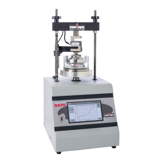
- Page 1 HM-5470.3F product manual 03.18 HM-5470 ConMatic IPC...
-
Page 3: Table Of Contents
CONTENTS Quick Start Guide System Information Unpacking Firmware Version Installation and Equipment Setup IP Information Electrical Connections Local Status Power Switch Internet Status Air Connection Memory Instrumentation Connections and Setup Factory Screen HM-5760 Rear Instrumentation Panel Export Log File Network Initial Set Up —... -
Page 4: Quick Start Guide
Unpacking Initial inspection should include checking for physical dam- age during shipping and obvious external damage to the product. Package contents are defined by your packing list. Each Loader is configured according to customer specifications. In your inspection, make certain that the contents of your shipment match the documentation provided by your pack- ing list. -
Page 5: Air Connection
Air Connection A constant supply of clean, dry air is required for operation. The air connection is located in the rear of the base cabinet, see photo below. The air connection is 1/4” (6mm) OD. Insert tubing (sup- plied) into the quick-connect until it bottoms out, and make sure the connections are tight. -
Page 6: Initial Machine Set-Up
Below are photos of an instrumentation input and the in- strumentation plug. Install the plugs into the inputs by lining up the guide at the bottom of the plug with the slot at the bottom of the input. Instrumentation Input Instrumentation Plug Once you have installed the instrumentation into the correct inputs, your rear panel should look like this:... - Page 7 DO NOT RECALIBRATE! When your HM-5470 is first turned on, the screen below will appear. From this screen, to confirm your machine instrumentation has been calibrated, navigate to the Calibration section by clicking the Menu icon in the top left corner of the screen (1). When you click on this button, you will see a drop-down menu appear, see below.
-
Page 8: Initial Set-Up - Calibration
Initial Set Up — Calibration Click on the Calibration tab in the top left corner (2). You will see the following screen. Calibration Input Screen The Calibration Input Screen (above) is used to monitor and calibrate instrumentation and assign them to specific chan- nels of the HM-5470. -
Page 9: Units
Calibration Input Screen, cont. Each channel has a “Limits On” check box (1). Use the Limits On to keep the machine from exceeding the sensor limits of the instrumentation. By selecting this option, before the test can exceed the limits of the sensors, all tests will stop run- ning and the motor will stop to avoid damaging connected instrumentation. -
Page 10: Export Calibration Via Usb
For the HM-5470, Vertical load = 2,000 lb and vertical displacement = 1.000”) Export Calibration via USB (4) Press this button to select calibrations to export via USB. It is a good practice to export all your calibrations to a thumb drive. -
Page 11: Date
Date (1) Set the month, day, year, and date display format. Time (2) Set the hours, minutes, seconds, and am/pm. Clock Style (3) Select a clock view, either a 24-hour or 12-hour clock, as well as the option to show seconds or not. Clock (4) The current time is displayed and is located on every control- ler screen. -
Page 12: Brightness
Brightness (1) Slide the gray bar to the left or right to adjust brightness. Dim Display (2) The backlight of the display will automatically dim to save power. Click the yellow box to change the number of min- utes before the display goes dim. After the time has elapsed, touch the display to deactivate dimming. -
Page 13: Preferences - General Tab
Click on the Preferences tab (1). You will see the following screen. Preferences – General Tab The Preferences panel is comprised of four (4) tabs and defaults to the General tab, see above. Logger ID (1) Each machine that is connected to your network requires a unique Logger ID. -
Page 14: Ambient Temperature
Ambient Temperature (1) This field displays the current ambient temperature and allows you to select desired units (Fahrenheit or Celsius) for temperature recording. Stress Control Unit (2) Click on the desired units you want to use for motor control. Preferences – Specimen Parameters Tab This screen is accessed by clicking on the Specimen Parame- ters Tab under System Preferences. -
Page 15: Specimen Height
Specimen Height (1) This field allows you to set the specimen height that will be used for all testing calculations. Specimen Diameter (2) This field allows you to set the specimen diameter that will be used for all testing calculations. Preferences –... -
Page 16: Initial Set Up - Network
Initial Set Up — Network To set up Network settings, return to the System Settings screen and click on the Network panel. (1) A password is required to access the Network Settings. That password is: 27604. -
Page 17: Network Settings Screen
Network Settings Screen The screen above is the Network Settings screen, it provides information on your IP information and network status. DHCP (1) Check this box to enable/disable the Dynamic Host Configu- ration Protocol (DHCP). If enabled, your machine will pick up IP information from your router. -
Page 18: System Information
System Information Below is a view of the System Information screen. It provides a current status of the machine. Firmware Version (1) The current version of the machine firmware is shown here. If you contact product support, you will need to supply this information. IP Information (2) This information will be filled in automatically if DHCP is checked, otherwise you will have to manually supply this in-... -
Page 19: Internet Status
This will provide us with the necessary in- formation to assist you and you will be added to the next position in the support cue. You can also email Humboldt Support at support@hum- boldtmfg.com or Humboldt Service at service@humboldtm- fg.com. Please include contact information and a detailed... -
Page 20: Initial Set Up - Update
Initial Set Up — Update Clicking on this panel provides information on checking for Updates, performing updates and an update history for the machine. (1) -
Page 21: Update From Usb
Once on this page, click on the Elite Series Firmware tab. You will see a list of Humboldt Elite Series machines. Click on the HM-5470 Current Version link and the firmware update will begin to download to your computer. Once the down- load is complete. -
Page 22: Check For Update
The update process will begin. This may take several min- utes. Your HM-5470 may reboot several times during the update, do not turn off or reset machine during this process. - Page 23 This manual covers the setup and operation of the HM-5470 ConMatic IPC, Automated Consolidation Machine in Stand- alone Mode only. For information on operating your load frame with Humboldt’s NEXT Software and Consolidation Module on a computer, please refer to the Humboldt NEXT software manual.
-
Page 26: Installation And Equipment Setup
Installation and Equipment Setup Electrical Connections The HM-5470 is equipped with an internal digital switching power supply, which allows it to be used with most power configurations throughout the world. The unit is supplied with an IEC electrical cord with a standard 110V plug. The HM-5470 arrives ready for operation. -
Page 27: Air Connection Accessories
95psi. Air Connection It is highly recommended that you use some type of refrigerant or desiccant dryer and regulator in your machine setup. Humboldt offers the following items for this purpose. Refrigeration Dryer, 115V 60Hz 1ph HM-4221 Compressed air quality is often overlooked in many labs. -
Page 28: Air Connection Accessories
Also, you will need a source of compressed air. Humboldt offers the following air compressors. Compressor, 120V 50/60Hz HM-4220 Compressor, 220V 50/60Hz HM-4220.4F When operating under full load this exceptionally quiet compressor offers a tremendously low noise level of 40 db/A. -
Page 29: Instrumentation Connections And Setup
Instrumentation Connections and Setup HM-5470 Rear Instrumentation Panel Above is a photo of the rear instrumentation panel of the HM-5470. Network (1) Ethernet input for connecting machine to a local area network and/or the internet. USB Power (2) The USB Power port is used for powering a wireless access appli- ance for those who want to use a wireless LAN setup. -
Page 30: Test Deck Setup
Once you have installed the instrumentation into the correct inputs, your rear panel should look like this: Test Deck Setup Below is a how your HM-5470 should be set up for operation. When you receive your unit, your instrumentation should already be mount- ed in place. -
Page 31: Consolidation Cell Placement
Consolidaton Cells Fixed Ring Consolidation Cell Floating Ring Consolidation Cell ASTM: D2435, D4546, AASHTO: T216, ASTM: D2435, D4546, AASHTO: T216, BS:1377:5 BS:1377:5 Complete cell assembly features stainless Complete cell assembly features stainless steel construction and self-trimming cutter steel construction with self-trimming cutter ring. - Page 32 Fixed Ring Permeability Cell ASTM: D2435, D4546, AASHTO: T216, BS:1377:5 Similar in construction to a fixed ring cell with the exception that the saturated sample and Load Pad water are sealed from the atmosphere. Com- Upper Stone plete cell assembly features stainless steel construction and self-trimming cutter ring.
-
Page 33: Consolidation Cells
Consolidation Cell Components – inches Consolidation Cell Components 2.0" 2.42" 2.5" 3.0" 4.0" Load pad HM-1220.20.10 HM-1220.24.10 HM-1220.25.10 HM-1220.30.10 HM-1220.40.10 HM-1220.25.11* Upper stone HM-4184.1985 HM-4184.240 HM-4184.2985 HM-4184.3985 HM-4184.2485 Lower stone (floating) HM-4184.1985 HM-4184.240 HM-4184.2485 HM-4184.2985 HM-4184.3985 Lower stone HM-4184.331 HM-4184.331 HM-4184.331 HM-4184.331 HM-4184.4375T... -
Page 34: Consolidation Cell Components - Inches
Consolidation Cell Components – metric Consolidation Cell Components 50mm 70mm 75mm 100mm Load pad HM-1220.50.10 HM-1220.70.10 HM-1220.75.10 HM-1220.100.10 Upper stone HM-4184.1955 HM-4184.274 HM-4184.2940 HM-4184.3925 Lower stone (floating) HM-4184.1955 HM-4184.274 HM-4184.2940 HM-4184.3925 Lower stone HM-4184.331 HM-4184.331 HM-4184.331 HM-4184.4375T (fixed & permability) Acrylic cylinder (fixed) HM-1220.25.2 HM-1220.25.2... -
Page 35: Calibration Of Instrumentation
How to Perform a Calibration All instrumentation included with this unit has been calibrated and assigned to specific channels for use. Humboldt recommends (and standard lab practice dictates) that your HM-5470 should be calibrat- ed periodically. For most, recalibration is conducted annually, though other rules may apply to the frequency of calibration. - Page 36 Once your calibrations have been saved, click on the trash can icon (5) to begin to erase both (2) Input calibrations. When you press the trash can icon, this screen will appear. On this screen select an Input calibration to delete, one at a time, and then press the Select button.
- Page 37 Calibrating your instrumentation to the appropriate Input requires a separate device, which can provide precise and specific loads or dis- placement, and, which has been certified to be accurate. The calibra- tion process involves plugging the instrumentation into the HM-5470 while placing the instrumentation into the certified calibration device, which provides a specific set load or displacement.
- Page 38 Upon filling in the password, you will see this screen, Tab 1 Sensor Details of the Calibration settings. On Tab 1, the Sensor Type (1) will default to Displacement Load. For Capacity (2), fill in the maximum capacity of the sensor and choose either lbf or kN.
- Page 39 Once this is complete, click on the Right Arrow in the bottom right- hand corner of the screen to save these settings. You will be taken to Tab 2, Limits. On Tab 2, in the Calibration Limit field (1), enter the maximum cal- ibrated limit of the sensor.
- Page 40 If you choose Multi-Point (Recommended calibration method) Curve and click on the Right Arrow in the bottom right-hand corner of the screen, you will be taken to Tab 3. On Tab 3 you will be able to set the number of points you want to use for your calibration.
- Page 41 Each point would be chosen by clicking on the corresponding point row above. The load would be applied to the sensor and an A/D Counts reading would appear. To set the point, click on the Set Point button (1). This would be repeated until all points have been set. In the example above, Point 3 is being calibrated and is ready to have the Set Point button (1) clicked.
-
Page 43: Test Setup
Test Setup To begin a new test, Click on the Menu icon in the top left corner of the screen (1). When you click on this button, you will see a drop- down menu appear, see below. Click on NEW TEST (1). Test Setup Wizard –... -
Page 44: Test Setup
Test Setup Wizard – Setup Target Load Click on the Load Value field (1) and a pop-up menu will appear. Use this menu to type in the value you want to use for the Load Value. Click the check mark in the lower right-hand corner of this pop-up menu to choose the value and you will be returned to the screen above. -
Page 45: Test Setup Wizard - Select Taget Load
Test Setup Wizard – Select Logging Values Choose Yes or No. (1). You will see the screen below. Choosing “Yes” ensures that the vertical displacement will be tared (zeroed) at the beginning of the test. Click on the Logging Value Icon (1). A new pop-up window will appear entitled Logging Time Table, see below. - Page 46 For those who want to use different parameters, you can either click on Use Default (1) and change the values to suit your application, or, click on Clear Table (2) and fill in the blank table with your values. Once you are satisfied with the completed table, click on the Select button (3) to use the Table.
- Page 47 Test Setup Wizard – Select Stop Parameters Next you need to select the Stop Parameters for the test. To choose the Stop Value Parameter, Click on the yellow field (1) and select a time period from the pop up window that appears. To save your Stop Value, click on the check mark (1) in the lower, right-hand corner of the pop up window.
-
Page 48: Test Setup Wizard - Select Stop Parameters
To proceed, click on the Right Arrow (1) in the lower, right-hand cor- ner of the screen. Test Setup Wizard – Select Trigger Parameters (Start Tab) On this screen (see below), the calibrated device should show up automatically in the Trigger Input field (1). The Trigger Value (2) and Current Value (3) should also be automatically filled in for that device. - Page 49 Once completed, press the Green Arrow at the bottom right-hand corner of the screen (4). You will then see the screen below. In the Value Field, create a name for your test (1). Press the check mark button (2) to save your test name. You will hear an extended beep sound indicating your test name has been saved.
- Page 50 Once completed, press the Green Arrow at the bottom right-hand corner of the screen (4) and you will be taken to the following screen and your test will begin. You can monitor your test from this window, which allows you to view the Displacement (1) and the Stress (2), or for additional information, click on the Test Control bar on the right of the window (3), which will reveal the additional panel shown below.
- Page 51 From this new panel you are given the Current Status of your test, in this case, Running (1). You can also see the number of points currently read (2) and the current duration of the test (3). In addition, by clicking on the Test View button (4) you can toggle through three different views of the current test.
- Page 52 This manual covers the setup and operation of the HM-5470 ConMatic IPC, Automated Consolidation Machine in Stand-alone Mode only. For information on operating your machine with Humboldt’s NEXT Software and Consolidation Module, on a computer, please refer to the Humboldt NEXT software manual.
- Page 53 The system automatically moves through the different test parameters specified by the user with incremental consolidation tests typically being completed in 24 to 48 hours. The Humboldt NEXT software uses sample deformation readings taken from the displacement transducer and load readings from the load cell to maintain a constant applied stress or strain to the sample through the use of an accurate stepper motor.
-
Page 54: Hm-547-.3F Specifications
Specifications: Controller Specifications: Sample size up to 4" (100mm) Display (Resistive Touch) 7" (178mm) VGA (480 x 800) Real-time test data Graphic and tabulation Maximum load 2200lbf (10kN) Processor Dual 32-bit ARM Clearance, vertical 8.25" (210mm) 64MB Clearance, horizontal 7.75" (197mm) Memory, non-volatile Maximum piston 0.5"... -
Page 55: General Warnings
The Humboldt Mfg. Co. liability under the warranty contained in this clause is limited to the repair or replacement of defective goods and making good, defective... - Page 56 99 years. Transfer of the license can be obtained by a request, in writing, from HUMBOLDT MFG. CO. With the exception of HUMBOLDT Authorized Service Facilities, you may not copy, alter, de-compile, or reverse assemble the software in any fashion except as instruct- ed in this manual.
Need help?
Do you have a question about the HM-5470.3F ConMatic IPC and is the answer not in the manual?
Questions and answers