Table of Contents
Advertisement
Quick Links
Advertisement
Table of Contents

Subscribe to Our Youtube Channel
Related Manuals for E-TOP BR486n


Summary of Contents for E-TOP BR486n
- Page 1 E-TOP 11n Broadband Router Wireless Broadband Router BR486n User Manual...
-
Page 2: Table Of Contents
Table of Contents CE Statement of Conformity ........................ 7 Notice ..............................8 Chapter 1 Introduction ......................... 9 Overview ........................9 Features ........................10 Specifications......................11 1.3.1 Views of Product Appearance.................13 1.3.2 LED Indicator Status Description ..............14 System Requirements ....................15 WAN Network Plug and Play..................15 Get Your IP Automatically &... - Page 3 5.1.1.7 WAN Access Type – L2TP................... 52 5.1.2 LAN Interface Setup ..................54 5.1.3 Dynamic DNS Setting..................55 Wireless Setup ......................57 5.2.1 Wireless Basic Settings...................57 5.2.2 Wireless Advanced Settings ................62 5.2.3 Wireless Security Setup ..................63 5.2.4 Wireless Access Control .................65 5.2.5 WDS Settings ....................67 5.2.6 WPS ........................71 NAT ..........................76...
- Page 4 System Management ....................119 6.3.1 Change Password ..................119 6.3.2 Save / Reload Settings...................120 6.3.3 Time Zone Setting ..................124 6.3.4 UPnP Setting....................125 Log & Status ......................126 6.4.1 Network Config....................126 6.4.2 Event Log ......................127 Logout ........................128 Chapter 7 Advance Configuration for WiFi AP Mode............129 IP Configuration ......................129 7.1.1 LAN Setup .......................129...
- Page 5 Others........................171 Chapter 10 Appendices......................172 10.1 Operating Systems ....................172 10.2 Browsers........................172 10.3 Communications Regulation Information ............172...
-
Page 7: Ce Statement Of Conformity
CE Statement of Conformity Our product has been tested in typical configuration by Ecom Sertech Corp and was found to comply with the essential requirement of “Council Directive on the Approximation of the Laws of the Member States relating to Electromagnetic Compatibility” (89/336/EEC; 92/31/EEC;... -
Page 8: Notice
Notice Changing RF parameter is not allowed. -
Page 9: Chapter 1 Introduction
Chapter 1 Introduction Overview 11N Broadband router is huge in functionality. It provides wired Ethernet and wireless WiFi interfaces for different needs. It has auto-detect to make plug and play more easy. -
Page 10: Features
Features Rigorous security 11n Broadband Router provides rigorous wireless security and firewall settings to protect user’s data in Internet. Easy-to-use and Plug-n-Play User-friendly GUI leads user to configure step by step. With wired connecting auto detection, user can connect Internet easily. High connecting quality QoS function can sort data or limit upload and download bandwidth by IP Address, port or MAC address set by user to improve the quality of network. -
Page 11: Specifications
Specifications Item Specification Key Components Main Processor Realtek RTL8196C (400MHz ) 2Mbytes Serial Flash Flash 16Mbytes SDRAM Wireless Chip Realtek RTL8192CE (MAC+BB+RF) 2T2R Communication Interfaces WAN Port 1 x 10/100 Mbps RJ45, with auto MDI/MDIX 4 x 10/100 Mbps RJ45, with auto MDI/MDIX LAN Port IEEE 802.11 b/g/n Wireless... - Page 12 Operating Temp. 0°C~40°C (32°F~104°F) Storage Temp. -20°C~70°C (-4°F~158°F) Operation Requirement Operating Humidity 10% to 85% Non-Condensing Storage Humidity 5% to 90% Non-Condensing Power Adapter DC5V/0.6A Power Supply 32mm*19mm*17mm CORE...
-
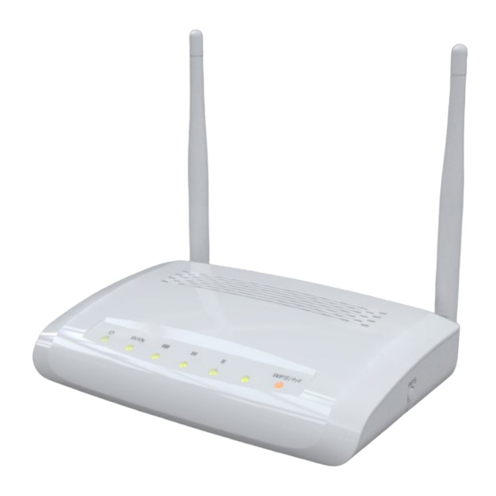
Page 13: Views Of Product Appearance
1.3.1 Views of Product Appearance Power Plug Power Adapter DC5V/0.6A Operation Mode Router, AP, and WiFi AP operation modes Switch Press “Reset” button over 10 seconds. When status indicator turns from Reset Button flashing to solid, the process is completed. All settings are back to default. 5 RJ-45 Ethernet 10/100 Ports Ethernet Port... -
Page 14: Led Indicator Status Description
1.3.2 LED Indicator Status Description Function Color Status Description System is ready to work 1. Power is being applied and system System status Power x 1 Green Blinking boot in progress 120ms 2. Reset in progress Wireless is connected Green Wireless activity Blinking Wireless Tx/Rx activity... -
Page 15: System Requirements
System Requirements To begin with 11N Broadband router, you must have the following minimum system requirements. If your system can’t correspond to the following requirements, you might get some unknown troubles on your system. XDSL/Cable Modem and broadband Internet Account. One Ethernet (10 BASE-T or 10/100 BASE-TX) network interface card. - Page 16 Step 2. Click on Properties Step 3. Double click on Internet Protocol (TCP/IP).
- Page 17 Step 4-1. For getting IP automatically if you are one of the users under 11N Broadband router, please skip Use the following IP address and then select Obtain an IP address automatically and Obtain DNS server address automatically and then click on OK button. Step 4-2.
-
Page 18: Network Testing
Default Gateway: 192.168.1.1 Note: If you configure your computer’s IP Address manually, it needs to be on the same network segment. For example: IP Address: 192.168.1.xxx (xxx can be any number between 2 and 253, but it can’t be repeated, we use 100 to be the example.) Subnet Mask: 255.255.255.0 Gateway: 192.168.1.1 (this is the IP address of 11N Broadband router in Router Mode) DNS: 192.168.1.1 (use 11N Broadband router’s IP address or on your own choice) -
Page 19: Testing With Dos (Windows Xp Platform)
1.6.2.1 Testing with DOS (Windows XP Platform) Step 1. Go to start -> Run. Step 2. Input cmd in the blank, and then click OK button. The Command Prompt window appears. Step 3. Input ipconfig in the flashing area then press enter. You will get an IP Address 192.168.1.100, for example, and Default Gateway as 192.168.1.1. - Page 20 Step 4. Ping a legal WAN Address such as 192.168.1.1. If Internet works, it will show Reply from 192.168.1.1: bytes = 32 time = 3ms TTL =64, for example. If it can’t work, it will show Request timed out.
-
Page 21: Chapter 2 Hardware Installation
Chapter 2 Hardware Installation Diagram of Connecting Hardware to 11N Broadband router 11N Broadband router is a portable and convenient wireless solution for the traveling businessmen delivering 802.11n wireless connectivity with a maximum wireless signal rate of up to 300Mbps. Use it in conference rooms, hotel rooms, or even at hotspots. The Wireless Pocket Router/AP might be small in size, but is huge in functionality, supporting multiple operation modes, including Access Point (AP) mode, Router mode, and WiFi AP mode. -
Page 22: Hardware Connection And Application For Ap Mode
2.1.2 Hardware Connection and Application for AP Mode Under AP Mode, it supports 2 LAN ports as Bridge, and user can connect to 11N Broadband Router via LAN port. The administrator can set up quickly, including LAN Setup, Wireless Setup, Time Server Setup, and Password Setup. 2.1.3 Hardware Connection and Application for Wi-Fi AP Mode As WiFi AP Mode, 11N Broadband Router will be a bridge and supports a wireless LAN. -
Page 24: Chapter 3 One Button Setup
Chapter 3 One Button Setup The advanced One Button Setup provides users a simple way to set up the complicated network. Instead of numbers of IPs to be memorized, you just need to fill in some necessary information and then enjoy the secured internet by clicking the “Finished” button. Any question, please refer “HELP”. - Page 25 Step 2. Click the Internet Gateway Device to open the login page. Step 3. Click One Button Setup on the left of the main menu under router mode.
-
Page 26: One Button Setup Configuration For Ap Mode
Time Zone Select: Select your time zone from the Time Zone drop-down list. Change Password: For changing password, please fill the password information into the blank. Device Name: Name your device here. The default is 11N_Mini_Router. Note: System will automatically copy the last 6 numbers of this device’s MAC address after your device name. WAN Interface Setup: Select the WAN Interface from the drop-down list. - Page 27 Step 1. Please plug in power. Step 2. Click the Internet Gateway Device to open the login page. Step 3. Click One Button Setup on the left of the main menu under AP mode.
-
Page 28: One Button Setup Configuration For Wifi Ap Mode
Time Zone Select: Select your time zone from the Time Zone drop-down list. Change Password: For changing password, please fill the password information into the blank. Device Name: Name your device here. The default is 11N_Mini_Router. Note: System will automatically copy the last 6 numbers of this device’s MAC address after your device name. Wireless Setup: Define the SSID, and Encryption type. - Page 29 Step 3. Click One Button Setup on the left of the main menu under WiFi AP mode.
- Page 30 Time Zone Select: Select your time zone from the Time Zone drop-down list. Change Password: For changing password, please fill the password information into the blank. Device Name: Name your device here. The default is 11N_Mini_Router. Note: System will automatically copy the last 6 numbers of this device’s MAC address after your device name. Wireless Site Survey Setting: Select the preferred AP for connection, and the encryption type.
- Page 31 Note: One Button Setup is not completed unless users finish all settings and click Finished button.
-
Page 32: Chapter 4 Basic Setup
Chapter 4 Basic Setup Open a Microsoft Internet Explorer, Mozilla Firefox or Apple Safari browser, and enter http://192.168.1.1 (Default Gateway) into browser’s blank. The default values for User Name and Password are admin (all in lowercase letters). Click Login to enter. -
Page 33: Router Mode
Router Mode Under Router Mode, the 11n Broadband Router provides a Router/AP function. User can get IP address assigned by ISP wired or wirelessly. It also supports NAT and DHCP functions that enable multiple computers to share an Internet connection at the same time. Please follow the steps: 1. - Page 34 3. Click Next. 4. Select time zone and NTP server, then click Next. 5. Set LAN Information, then click Next.
- Page 35 6. Set up WAN Interface, then click Next. 7. Configure Wireless Basic Settings and click Finished.
-
Page 36: Ap Mode
AP Mode Under AP Mode, the 11N Broadband Router supports 2 LAN ports as Bridge, and user can connect to this Router via LAN port and provide the lower level wired or wireless internet connections. NAT function is disabled under AP mode. The 11N Broadband Router connects the upper level device only through the Ethernet port and gets its assigned IP address. - Page 37 3. Click Next. 4. Select time zone and NTP server, then click Next. 5. Configure Wireless Basic Settings and click Finished.
-
Page 38: Wifi Ap Mode
WiFi AP Mode As WiFi AP Mode, 11N Broadband Router will be a bridge and support a wireless LAN. NAT function is disabled under WiFi AP mode. The 11N Broadband Router connects the upper level device wirelessly and gets its assigned IP address. If not, the 11N Broadband Router will use the default IP or assigned by the user. - Page 39 3. Click Next. 4. Select time zone and NTP server, then click Next.
- Page 40 Choose the access point that you want to connect, then click Next. 6. Configure Wireless Basic Settings and click Finished.
-
Page 41: Chapter 5 Advanced Configuration For Router Mode
Chapter 5 Advanced Configuration for Router Mode IP Configuration This function allows you to add routing rules into 11N Broadband router. It is useful if you connect several computers behind 11N Broadband router to share the same connection to Internet. 5.1.1 Select WAN under the IP Config menu. -
Page 42: Wan Interface- Wireless
5.1.1.2 WAN Interface– Wireless If you are connecting the internet via wireless, please select Wireless and its associated settings will show up underneath at the same time. You can see a list of available Wireless networks. Select you preferred one to connect and the Encryption type form the drop-down list. -
Page 43: Wan Access Type - Static Ip
5.1.1.3 WAN Access Type – Static IP If you applied for a Static IP connection type from ISP, please follow the steps to set up your WAN connection. - Page 44 IP Address Input your IP Address supplied by ISP. If you don’t know, please check with your ISP. Subnet Mask Input Subnet Mask, normally it is 255.255.255.0. Default Gateway Input ISP Default Gateway Address. If you don’t know, please check with your ISP. MTU Size MTU stands for Maximum Transmission Unit.
-
Page 45: Wan Access Type - Dynamic Ip
select Set DNS Manually and input the DNS information into the blank. Clone MAC Address Copy the MAC address from the device you had registered to your ISP if your ISP asks for the specific MAC Address. Enable IGMP Proxy The Internet Group Management Protocol (IGMP) is a communication protocol used to manage the membership of Internet Protocol multicast groups. - Page 46 Host Name The host name is optional; but if your ISP requires you to input a specific host name, please put it in, for example, 11N Broadband router applied from ISP. Generally, Cable Modem will provide the hostname information. MTU Size MTU stands for Maximum Transmission Unit.
-
Page 47: Wan Access Type - Pppoe
Enable IGMP Proxy The Internet Group Management Protocol (IGMP) is a communication protocol used to manage the membership of Internet Protocol multicast groups. IGMP is used by IP hosts and adjacent multicast routers to establish multicast group memberships. You can choose to enable IGMP Proxy to provide service. - Page 48 User Name Input your user name supplied by ISP. If you don’t know, please check with your ISP. Password Input your Password supplied by ISP. Service Name Input the service name supplied by ISP. Connection Type It has three types: Continuous, Connect on Demand, and Manual. Idle Time It is the time of inactivity before disconnecting your PPPoE session.
- Page 49 minutes) to define a maximum period of time for which the Internet connect is maintained during inactivity. If the connection is inactive for longer than the defined Idle Time, then the connection will be dropped. Either set this to zero or enable Auto-reconnect to disable this feature.
-
Page 50: Wan Access Type - Pptp
5.1.1.6 WAN Access Type – PPTP If you have applied for a PPTP connection type from ISP, please follow the steps to set up your WAN connection. IP Address Input your IP Address supplied by ISP. If you don’t know, please check with your ISP. Subnet Mask Input Subnet Mask, normally it is 255.255.255.0. - Page 51 Input the PPTP Account supplied by ISP, for example. If you don’t know, please check with your ISP. Password Input the Password supplied by ISP. MTU Size MTU stands for Maximum Transmission Unit. For PPPoE connection, the default MTU should be provided by computer operating systems (OS).
-
Page 52: Wan Access Type - L2Tp
This option is to enable Web Server Access function on WAN. 13. Apply Changes & Reset Click on Apply Changes to save the setting data. Or you may click on Reset to clear all the input data. 5.1.1.7 WAN Access Type – L2TP If you have applied for a L2TP connection type from ISP, please follow the steps to set up your WAN connection. - Page 53 Input your Server IP Address supplied by ISP. If you don’t know, please check with your ISP. User Name Input the L2TP Account. Password Input the Password. MTU Size MTU stands for Maximum Transmission Unit. For PPPoE connection, the default MTU should be provided by computer operating systems (OS).
-
Page 54: Lan Interface Setup
5.1.2 LAN Interface Setup Use this page to set up the local IP address and subnet mask for your router. Please select LAN Interface Setup under the IP Config menu and follow the instructions below to enter the LAN setting page to configure the settings you want. IP Address The default value of LAN IP address is 192.168.1.1 for this router. -
Page 55: Dynamic Dns Setting
DHCP Client Range Define the DHCP client range and then the DHCP server will assign an IP to the requesting computer from this range. The Show Client will display every assigned IP address, MAC address, and expired time. The default range is 192.168.1.100 - 192.168.1.200. 802.1d Spanning Tree IEEE 802.1d Spanning Tree Protocol (STP) is a link layer network protocol that ensures a loop-free topology for any bridged LAN. - Page 56 Enable / Disable DDNS Select enable to use DDNS function. Each time your IP address to WAN is changed, and the information will be updated to DDNS service provider automatically. Service Provider Choose correct Service Provider from drop-down list, here including DynDNS, TZO, ChangeIP, Eurodns, OVH, NO-IP, ODS, Regfish embedded in 11N Broadband router.
-
Page 57: Wireless Setup
Wireless Setup 11N Broadband router enables fastest 300 Mbps IEEE802.11g wireless transmissions and keeps compatibility with existing IEEE 802.11n devices. 11N Broadband router complies with IEEE 802.11b/g standard. Please select Wireless under the main menu. 5.2.1 Wireless Basic Settings Follow the instructions to configure the Wireless settings. - Page 58 Disable Wireless LAN Interface Select Disable Wireless LAN Interface to turn off the wireless function. Band This field indicates the 802.11x interface mode. For example, “2.4GHz(G)” prevents the 802.11b clients from accessing the router. “2.4GHz(B+G)” allows both 802.11b and 802.11g clients to access the router.
- Page 59 Multiple APs Click Multiple APs to set up 4 different SSIDs to deploy a shared WLAN. Users can add or limit the properties for each SSID, increasing the flexibility and efficiency of the network. (1.) Enable: check it for enable or not. (2.) Band: select the frequency from the drop down list.
- Page 60 Channel Width Please select “20MHZ” or “40MHZ” channel width to change the transmission channels. ControlSideband Setting the Sideband "Upper" or "lower.” Channel Number Please select your wireless network channel. There are Auto, 2~11. Broadcast SSID Enable or disable the SSID broadcast function. Disable this feature can provide more security of your WLAN.
- Page 61 and Click on Apply Changes to save the setting Note: The DHCP server should be disabled under menu “LAN Interface Setup” and then the URM could be enabled. Step 3. Check the AP connectors and the Wireless connecting status. 14. SSID of Extended Interface When mode is set to “AP”...
-
Page 62: Wireless Advanced Settings
5.2.2 Wireless Advanced Settings Please follow the instructions to configure the Wireless settings. Fragment Threshold To identify the maximum length of packet, the overflow packet length wil be fragmentized. The allowed range is 256-2364, and default length is 2346 bytes. RTS Threshold This value should remain at its default setting of 2347. -
Page 63: Wireless Security Setup
throughput. Short GI Enabling the Short Guard Interval increases the wireless transmission. Apply Changes & Reset Click on “Apply Changes” to save the setting data. Or you may click on “Reset” to clear all the input data. 5.2.3 Wireless Security Setup 4 encryption types can be selected here, please follow the instructions below for each. - Page 64 802.1x Authentication Enable 802.1x Authentication so that a wireless node must be authenticated before it can gain access to other LAN resources. Key Length: For 64bits WEP key, either 5 ASCII characters or 10 hexadecimal digitals leading by 0x can be entered. For 128bits WEP key, either 13 ASCII characters or 26 hexadecimal digits leading by 0x can be entered.
-
Page 65: Wireless Access Control
WPA Authentication Mode Enterprise (RADIUS): Please input the port, IP address, and password of authentication RADIUS Server. Personal (Pre-Shared Key): Pre-Shared Key type is coding in ASCII, and the length is between 8 to 63 characters. If the coding is in Hex, the key length is 64 characters. - Page 66 Wireless Access Control Mode “Allowed Listed” means only the MAC address listed on the allowed list can access to your wireless network. “Deny Listed” means the listed MAC Address are not allowed to link to your wireless network. “Disable” for function disuse. MAC Address Please input the allowed or denied MAC address, for example, 001122334455.
-
Page 67: Wds Settings
5.2.5 WDS Settings WDS (Wireless Distribution System) is a Wireless Access Point mode that enables wireless bridging in which only WDS APs communicate with each other (without allowing for wireless clients or stations to access them), and/or wireless repeating in which APs communicate both with each other and with wireless stations (at the expense of half the throughput). - Page 68 Step 2. Get back to the menu “Wireless Basic Settings” of 11N Broadband router. Select AP+WDS mode, and then select the Channel Number. Click Apply Changes to save the setting data. Step 3. Enter the WDS Settings page, select Enable WDS, and then input the MAC...
- Page 69 address of the paired device. Click Apply Changes to save the setting data. Step 4. When the time counts down to 0, you will see the MAC address of the paired device displaying on Current WDS AP List. Step 5. Head back to LAN Interface, disable DHCP option, and then click Apply Changes to save the setting data.
- Page 70 Step 6. Doing the same way to setup the MAC address in the paired device. Launch the UT to the menu “WDS settings” of the paired device, and input router’s MAC address. Click Apply Changes to save the setting data. Input the MAC address here.
-
Page 71: Wps
Step 8. You can input http://192.168.9.9 in IE browser to enter the GUI page of the paired device and make sure the connection. 5.2.6... - Page 72 Wi-Fi Protected Setup (WPS) is an easy way to establish a secured wireless network between 11N Broadband router and wireless card. Users do not need to manually entering a creative, yet predictable security key on both Wi-Fi devices to prevent unwanted access to their wireless network.
- Page 73 (2.) Open the “Wireless Utility” of your wireless card, and click its “PBC” button, to start auto pairing.
- Page 74 (3.) While scanning is successful, the information of the wireless card appears in the windows below.
- Page 75 Start PIN: (1.) Open the “Wireless Utility” of your wireless card. Follow its PIN instruction to get a new PIN number. Write it down. (2.) Open menu “Wi-Fi Protected Setup” of 11N Broadband router, input the PIN number from the wireless card then click Start PIN. Enter the PIN Code you got from the wireless card.
-
Page 76: Nat
(3.) Back to “Wireless Utility” and press the “Start PIN” button to complete the auto-paring process. NAT is a method of mapping one or more IP addresses and/or services ports into different specified services, where NAT stands for Network Address Translation. It allows the internal IP addresses of many computers on a Local Area Network (LAN) to be translated to one public address, saving users’... - Page 77 Enable Port Forwarding Enable Port Forwarding to allow an external user to reach a port within a private LAN. IP Address Specify the private IP address of the internal host offering the service. Protocol Specify the transport layer protocol (TCP or UDP). Port Range Enter the Start and End ports in the range you'd like to forward.
-
Page 78: Visual Dmz
It will display all port forwarding regulation you made. Delete Selected & Delete All Click Delete Selected will delete the selected item. Click Delete All will delete all items in this table. Reset You can click Reset to cancel. Port Forwarding The following figure shows the ip forwarding configuration of your web on a local area network. -
Page 79: Firewall
Enable DMZ Check Enable to apply Virtual DMZ for the Router. DMZ Host IP Address This field stands for the destination IP address that you like to redirect the matched packet to. Apply Changes & Reset Click on Apply Changes to save the setting data. Or you may click on Reset to clear all the input data. -
Page 80: Port Filtering
5.4.1 Port Filtering This function allows users to filter and manage specific ports; to limit the use of certain applications to transmit through a specific port. Port filtering helps users to improve the security of your network. Enable Port Filtering Check Enable Port Filtering to start the service. -
Page 81: Ip Filtering
It will display all ports that are filtering now. Delete Selected & Delete All Click Delete Selected will delete the selected item. Click Delete All will delete all items in this table. Reset You can click Reset to cancel. Port Filtering The following figure shows a user limits some applications to use the 80 port. - Page 82 Enable IP Filtering Check enable or disable to apply IP Filter function. Local IP Address Please enter the IP address that needs to be filtered. Protocol Please select the protocol type of the IP address. Comment You can add comments for this regulation. Apply Changes &...
-
Page 83: Mac Filtering
You can click Reset to cancel. 5.4.3 MAC Filtering Use MAC filters to deny LAN computers by their MAC addresses from accessing the Internet. You can manually add a MAC address that is currently connected to 11N Broadband router. Enable MAC Filtering Check enable or disable to apply MAC Filter function. -
Page 84: Url Filtering
Delete Selected & Delete All Click Delete Selected will delete the selected item. Click Delete All will delete all items in this table. Reset You can click Reset to cancel. 5.4.4 URL Filtering Keyword based URL (Uniform Resource Locator) filtering allows you to define one or more keywords that should not appear in URL’s. -
Page 85: System Management
Click on Apply Changes to save the setting data. Or you may click on Reset to clear all the input data. Current Filter table Shows all filtered URL information. Delete Selected & Delete All Click Delete Selected will delete the selected item. Click Delete All will delete all items in this table. -
Page 86: Save / Reload Settings
Users can set or change their password in this section. New Password Enter the new password you want to change. New Password (Confirm) Enter the new password again for confirming. Apply & Cancel Click Apply to continue or Cancel to clear the settings on this page. Note: 1. - Page 87 location. A pop window will show up and ask to save config.dat file. Step 2. Please select the location, for example: the desktop.
- Page 88 Step 3. The file you just saved will appear on the desktop. Load Settings From File Step 1. Click on “Browse…” button for searching the saving configuration from hard drive, and then click on Upload button to load all the settings into the router. Step 2.
- Page 89 Step 4. When you see the screen below, the updating is completed. Please click OK to return to the main menu. Reset Setting to Default After you have tried other methods for troubleshooting your network, you may choose to restore 11N Broadband router to the factory default settings.
-
Page 90: Time Zone Setting
When you see the screen below, the resetting is completed. Please click OK and return to the main menu. 5.5.3 Time Zone Setting The System time is the time used by 11N Broadband router for scheduling services. You can manually set the time or connect to a NTP (Network Time Protocol) server. If a NTP server is set, you will only need to set the time zone. - Page 91 Current Time Users can input the time manually. Time Zone Select Select your time zone location from the drop-down list. Enable NTP client update Check to enable NTP client update. Automatically Adjust Daylight Saving If you are in daylight saving time area, please enable this item. NTP server Please select the NTP server from the pull-down list, or you can enter the NTP server IP address manually.
-
Page 92: Upnp Setting
Choose “General Time Server” and select the NTP Server from the drop-down list or choose “Customized Time Server” and enter the server by manual. 5.5.4 UPnP Setting UPnP (Universal Plug and Play) allows users to connect their UPnP-enabled Broadband router, printer server and other devices right to the network with zero-configuration, meaning easier setup for installing the device on the network. -
Page 93: Network Config
11N Broadband router provides the log list and connection status for user to check. 5.6.1 Network Config Network Configuration shows the firmware version and the connection status of LAN, WAN and Wireless. 5.6.2 Event Log... - Page 94 11N Broadband router provides system logs for review. Enable Log Select Enable Log to record the system log system all, wireless & DoS Select Wireless, DoS or system all to record Enable Remote Log You may choose to enable the remote event log or not. Log Server IP Address Please input the log server IP Address.
-
Page 95: Logout
After clicking Apply Changes to record the event log, it will be shown as the example below. Logout Click Logout on the bottom menu to exit and go back to GUI login home page. -
Page 96: Chapter 6 Advance Configuration For Ap Mode
Chapter 6 Advance Configuration for AP Mode IP Configuration This function allows you to add routing rules into 11N Broadband Router , including LAN and Site Survey. 6.1.1 LAN Setup Use this page to set up the local IP address and subnet mask for your router. Please select LAN under the IP Config menu and follow the instructions below to enter the LAN setting page to configure the settings you want. - Page 97 IP Address The default value of LAN IP address is 192.168.1.254 for this router. Subnet Mask Input Subnet Mask, normally it is 255.255.255.0. Default Gateway Input ISP Default Gateway Address. If you don’t know, please check with your ISP. DHCP Enable or disable DHCP services.
-
Page 98: Wireless Setup
loop-free topology for any bridged LAN. The main purpose of STP is to ensure that you do not create loops when you have redundant paths in your network. Loops are deadly to a network. Clone MAC Address Copy the MAC address from the device you had registered to your ISP if your ISP asks for the specific MAC Address. - Page 99 Disable Wireless LAN Interface Select Disable Wireless LAN Interface to turn off the wireless function. Band This field indicates the 802.11x interface mode. For example, “2.4GHz(G)” prevents the 802.11b clients from accessing the router. “2.4GHz(B+G)” allows both 802.11b and 802.11g clients to access the router.
- Page 100 Click Multiple APs to set up 4 different SSIDs to deploy a shared WLAN. Users can add or limit the properties for each SSID, increasing the flexibility and efficiency of the network. (1.) Enable: check it for enable or not. (2.) Band: select the frequency from the drop down list.
Need help?
Do you have a question about the BR486n and is the answer not in the manual?
Questions and answers