Table of Contents
Advertisement
Service
Manual
HIGH POWER CD PLAYER WITH FM/AM TUNER
DEH-5
DEH-15
DEH-1500
- This service manual should be used together with the following manual(s):
Model No.
Order No.
CX-3026
CRT2944
For details, refer to "Important symbols for good services".
PIONEER CORPORATION
PIONEER ELECTRONICS (USA) INC.
PIONEER EUROPE NV
Haven 1087 Keetberglaan 1, 9120 Melsele, Belgium
PIONEER ELECTRONICS ASIACENTRE PTE.LTD. 253 Alexandra Road, #04-01, Singapore 159936
C PIONEER CORPORATION 2002
XU/UC
XU/UC
XU/UC
Mech. Module Remarks
S10
CD Mech. Module:Circuit Description, Mech.Description, Disassembly
4-1, Meguro 1-Chome, Meguro-ku, Tokyo 153-8654, Japan
P.O.Box 1760, Long Beach, CA 90801-1760 U.S.A.
DEH-5/XU/UC
ORDER NO.
CRT2968
K-ZZU. NOV. 2002 Printed in Japan
Advertisement
Table of Contents

Related Manuals for Pioneer DEH-5/XU/US


Summary of Contents for Pioneer DEH-5/XU/US
- Page 1 PIONEER ELECTRONICS (USA) INC. P.O.Box 1760, Long Beach, CA 90801-1760 U.S.A. PIONEER EUROPE NV Haven 1087 Keetberglaan 1, 9120 Melsele, Belgium PIONEER ELECTRONICS ASIACENTRE PTE.LTD. 253 Alexandra Road, #04-01, Singapore 159936 C PIONEER CORPORATION 2002 K-ZZU. NOV. 2002 Printed in Japan...
-
Page 2: Safety Information
SAFETY INFORMATION CAUTION This service manual is intended for qualified service technicians; it is not meant for the casual do-it-yourselfer. Qualified technicians have the necessary test equipment and tools, and have been trained to properly and safely repair complex products such as those covered by this manual. Improperly performed repairs can adversely affect the safety and reliability of the product and may void the warranty. -
Page 3: Table Of Contents
CONTENTS SAFETY INFORMATION ............................2 1. SPECIFICATIONS ...............................4 2. EXPLODED VIEWS AND PARTS LIST........................6 2.1 PACKING................................6 2.2 EXTERIOR(DEH-5/XU/UC) ...........................8 2.3 EXTERIOR(DEH-15/XU/UC,1500/XU/UC)......................10 2.4 CD MECHANISM MODULE ..........................12 3. BLOCK DIAGRAM AND SCHEMATIC DIAGRAM ....................14 3.1 BLOCK DIAGRAM ..............................14 3.2 OVERALL CONNECTION DIAGRAM(GUIDE PAGE) ..................18 3.3 KEYBOARD UNIT ...............................24 3.4 CD MECHANISM MODULE ..........................26 4. -
Page 4: Specifications
1. SPECIFICATIONS - DEH-5/XU/UC DEH-5/XU/UC... - Page 5 - DEH-15/XU/UC,DEH-1500/XU/UC DEH-5/XU/UC...
-
Page 6: Exploded Views And Parts List
2. EXPLODED VIEWS AND PARTS LIST 2.1 PACKING NOTE: - Parts marked by “*” are generally unavailable because they are not in our Master Spare Parts List. ∇ mark on the product are used for disassembly. - Screws adjacent to - For the applying amount of lubricants or glue, follow the instructions in this manual. - Page 7 (2) CONTRAST TABLE DEH-5/XU/UC , DEH-15/XU/UC and DEH-1500/XU/UC are constructed the same except for the following: Part No. Mark No. Symbol and Description DEH-5/XU/UC DEH-15/XU/UC DEH-1500/XU/UC 11-1 Owner's Manual CRD3666 CRD3664 CRD3664 11-2 Installation Manual CRD3667 CRD3665 CRD3665 11-4 Caution Card Not used CRP1294 Not used...
-
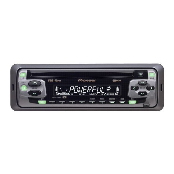
Page 8: Exterior(Deh-5/Xu/Uc)
2.2 EXTERIOR(DEH-5/XU/UC) DEH-5/XU/UC... - Page 9 - EXTERIOR(DEH-5/XU/UC) SECTION PARTS LIST Mark No. Description Part No. Mark No. Description Part No. 1 Screw BSZ26P060FTC 49 Rubber CNV7368 2 Screw BSZ30P060FTC 50 Connector CNV7369 3 Screw BSZ30P200FTC 4 Cord Assy CDE7060 51 Grille Unit CXB9805 5 Cable CDE7113 52 Screw ISS26P055FTC...
-
Page 10: Exterior(Deh-15/Xu/Uc,1500/Xu/Uc)
2.3 EXTERIOR(DEH-15/XU/UC,1500/XU/UC) DEH-5/XU/UC... - Page 11 - EXTERIOR(DEH-15/XU/UC, 1500/XU/UC) SECTION PARTS LIST Mark No. Description Part No. Mark No. Description Part No. 1 Screw BSZ26P060FTC LCD(LCD1801)(DEH-1500) CAW1733 2 Screw BSZ30P060FTC 46 Connector(CN1801) CKS3580 3 Screw BSZ30P200FTC 47 Holder CNC9617 4 Cord Assy CDE7060 48 Sheet CNM7932 5 Cable CDE7113 49 Lens...
-
Page 12: Cd Mechanism Module
2.4 CD MECHANISM MODULE DEH-5/XU/UC... - Page 13 - CD MECHANISM MODULE SECTION PARTS LIST Mark No. Description Part No. Mark No. Description Part No. 1 CD Core Unit(S10) CWX2708 48 Holder CNV7202 2 Connector(CN101) CKS4182 49 Arm CNV7203 3 Connector(CN701) CKS4188 50 Gear CNV7207 4 Screw BMZ20P035FTC 5 Screw BSZ20P040FTC 51 Gear...
-
Page 14: Block Diagram And Schematic Diagram
3. BLOCK DIAGRAM AND SCHEMATIC DIAGRAM 3.1 BLOCK DIAGRAM - DEH-5/XU/UC TUNER AMP UNIT 10 9 8 IC 5 IC 3 EEPROM 3.3V 5.0V ANTENNA CN402 AM ANT FMRF IC 2 2.5V IC 1 FM ANT 3.3V FMRF MIXER, IF AMP DET, FM MPX RF adj ANT adj... - Page 15 CN352 REAR L CH TUNPCE2 Q 352 TUNPCE1 TUNPDI TUNPDO TUNPCK Q453 LDET VDD REGULATOR Q911 SYS 8V REGULATOR Q921 Q922 CN901 SYSTEM CONTROLLER SYSPW BACKUP IC 601 (1/2) Q923 PE5331A BACK UP POWER AMP VST/ VCK/ VDT IN2_L ELECTRONIC VOLUME IC 302 Frontout_L IN3_L...
- Page 16 - DEH-15/XU/UC,1500/XU/UC TUNER AMP UNIT 10 9 8 IC 5 IC 3 EEPROM 3.3V 5.0V ANTENNA CN402 AM ANT FMRF IC 2 2.5V IC 1 FM ANT 3.3V FMRF MIXER, IF AMP DET, FM MPX RF adj ANT adj CF52 CF51 IC 4 3.3V...
- Page 17 CN352 REAR L CH TUNPCE2 Q 352 TUNPCE1 TUNPDI TUNPDO TUNPCK Q453 LDET VDD REGULATOR Q911 SYS 8V REGULATOR Q921 Q922 CN901 SYSTEM CONTROLLER SYSPW BACKUP IC 601 (1/2) Q923 PE5330A BACK UP VST/ VCK/ VDT POWER AMP IN2_L ELECTRONIC VOLUME IC 302 Frontout_L IN3_L...
-
Page 18: Overall Connection Diagram(Guide Page)
3.2 OVERALL CONNECTION DIAGRAM(GUIDE PAGE) Note: When ordering service parts, be sure to refer to " EXPLODED VIEWS AND PARTS LIST" or "ELECTRICAL PARTS LIST". Large size SCH diagram CN701 Guide page Detailed page CN1801 NOTE : Symbol indicates a resistor. Decimal points for resistor No differentiation is made between chip resistors and and capacitor fixed values... - Page 19 TUNER AMP UNIT REAR L CH REAR R CH CEK1136 > DEH-5/XU/UC...
- Page 20 FM/AM TUNER UNIT DEH-5/XU/UC...
- Page 21 R UNIT DEH-5/XU/UC...
- Page 22 DEH-5/XU/UC...
- Page 23 DEH-5/XU/UC...
-
Page 24: Keyboard Unit
3.3 KEYBOARD UNIT DEH-5/XU/UC... - Page 25 KEYBOARD UNIT LOUD CLOCK 40mA, 14V LOC/BSM DEH-5/XU/UC...
-
Page 26: Cd Mechanism Module
3.4 CD MECHANISM MODULE Pickup Unit(Service)(P10) MOTOR DRIVER SPINDLE MOTOR M1 CXB6007 LOADING/CARRIAGE MOTOR M2 CXB8933 3.3V REGULATOR DEH-5/XU/UC... - Page 27 SIGNAL LINE FOCUS SERVO LINE TRACKING SERVO LINE CARRIAGE SERVO LINE SPINDLE SERVO LINE SWITCHES: CD CORE UNIT S901 : HOME SWITCH..ON-OFF S902 : CLAMP SWITCH..ON-OFF S903 : DSCSNS SWITCH..ON-OFF RF AMP / SERVO / DSP S904 : 12EJ SWITCH..ON-OFF S905 : 8EJ SWITCH..ON-OFF DAC / LPF The underlined indicates the switch position.
- Page 28 - Waveforms Note : 1. The encircled numbers denote measuring points in the circuit diagram. 2. Reference voltage REFO1(1.65V) 1 DSCSNS 1 DSCSNS 5 SIN 5V/div 500ms/div 5V/div 500ms/div 1V/div 2s/div 2 CLCONT 2 CLCONT 6 CIN 5V/div 5V/div 500mV/div 3 LOEJ 3 LOEJ 7 TIN...
- Page 29 # RFAGC # RFAGC # RFAGC 1V/div 500ms/div 1V/div 5ms/div 1V/div 500µs/div 0 TE 0 TE 7 TIN 500mV/div 500mV/div 1V/div 7 TIN 7 TIN 0 TE 500mV/div 500mV/div 1V/div 8 FIN 1V/div 32 Track Jump 100(32x3) Track Jump When reproducing black dots(1mm) Ref.: Ref.: Ref.:...
-
Page 30: Pcb Connection Diagram
4. PCB CONNECTION DIAGRAM 4.1 TUNER AMP UNIT NOTE FOR PCB DIAGRAMS TUNER AMP UNIT 1.The parts mounted on this PCB include all necessary parts for CORD ASSY several destination. For further information for respective destinations, be sure to check with the schematic dia- gram. - Page 31 SIDE A ANTENNA FRONT DEH-5/XU/UC...
- Page 32 TUNER AMP UNIT DEH-5/XU/UC...
- Page 33 SIDE B DEH-5/XU/UC...
-
Page 34: Keyboard Unit
4.2 KEYBOARD UNIT SIDE B SIDE A KEYBOARD UNIT KEYBOARD UNIT CN831 DEH-5/XU/UC... - Page 35 DEH-5/XU/UC...
-
Page 36: Cd Mechanism Module
4.3 CD MECHANISM MODULE SIDE A CD CORE UNIT(S10) LOADING /CARRIAGE MOTOR SPINDLE MOTOR CN651 HOME PICKUP UNIT (SERVICE)(P10) DEH-5/XU/UC... - Page 37 SIDE B CD CORE UNIT(S10) 12EJ DSCSNS CLAMP DEH-5/XU/UC...
-
Page 38: Electrical Parts List
5. ELECTRICAL PARTS LIST NOTES: - Parts whose parts numbers are omitted are subject to being not supplied. - The part numbers shown below indicate chip components. Chip Resistor RS1/_S___J,RS1/__S___J Chip Capacitor (except for CQS..) CKS.., CCS.., CSZS..=====Circuit Symbol and No.===Part Name Part No. - Page 39 =====Circuit Symbol and No.===Part Name Part No. =====Circuit Symbol and No.===Part Name Part No. ------ ------------------------------------------ ------------------------- ------ ------------------------------------------ ------------------------- RS1/16S104J Unit Number : CWM8568(DEH-15) RS1/16S473J Unit Number : CWM8794(DEH-1500) Unit Name : Tuner Amp Unit RD1/4PU102J RS1/16S822J MISCELLANEOUS RS1/16S0R0J RD1/4PU221J PML003AM RD1/4PU221J...
- Page 40 =====Circuit Symbol and No.===Part Name Part No. =====Circuit Symbol and No.===Part Name Part No. ------ ------------------------------------------ ------------------------- ------ ------------------------------------------ ------------------------- RS1/16S681J CCSRCH100D50 RS1/16S681J CCSRCH100D50 RS1/16S681J CCSRCH100D50 RS1/16S0R0J CCSRCH100D50 RS1/16S681J CKSRYB104K16 RS1/16S473J CEJQ470M10 RS1/16S103J CEJQ100M16 RS1/16S153J CFTNA224J50 RS1/16S221J CFTNA224J50 RD1/4PU681J CFTNA224J50 RS1/16S473J CFTNA224J50 RS1/16S103J...
- Page 41 =====Circuit Symbol and No.===Part Name Part No. =====Circuit Symbol and No.===Part Name Part No. ------ ------------------------------------------ ------------------------- ------ ------------------------------------------ ------------------------- LCD1801 LCD(DEH-15) CAW1765 RS1/16S393J RS1/16S122J LCD1801 LCD(DEH-1500) CAW1733 RS1/16S562J RS1/16S472J RESISTORS RS1/16S0R0J 1801 RS1/16S222J RS1/16S103J 1802 RS1/16S222J RS1/16S103J 1803 RS1/16S471J RS1/16S183J 1804 RS1/16S471J...
- Page 42 =====Circuit Symbol and No.===Part Name Part No. ------ ------------------------------------------ ------------------------- CKSRYB103K25 CKSRYB104K16 CKSRYB103K25 CKSRYB103K25 100µF/16V CCH1504 CKSRYB224K16 CKSRYB104K16 10µF/6.3V CCH1470 Miscellaneous Parts List Pickup Unit(Service)(P10) CXX1641 Motor Unit(SPINDLE) CXB6007 Motor Unit(LOADING/CARRIAGE) CXB8933 DEH-5/XU/UC...
-
Page 43: Adjustment
6. ADJUSTMENT 6.1 CD ADJUSTMENT 1) Cautions on adjustments 2) Test mode • In this product the single voltage (3.3V) is used for the This mode is used to adjust the CD mechanism module. regulator. The reference voltage is the REFO1 (1.65V) •... -
Page 44: Checking The Grating After Changing The Pickup Unit
6.2 CHECKING THE GRATING AFTER CHANGING THE PICKUP UNIT • Note : The grating angle of the PU unit cannot be adjusted after the PU unit is changed. The PU unit in the CD mechanism module is adjusted on the production line to match the CD mechanism module and is thus the best adjusted PU unit for the CD mechanism module. - Page 45 Ech → Xch 20mV/div, AC Grating waveform Fch → Ych 20mV/div, AC 0° 30° 45° 60° 75° 90° DEH-5/XU/UC...
-
Page 46: Error Mode
6.3 ERROR MODE - Error Messages If a CD is not operative or stopped during operation due to an error, the error mode is turned on and cause(s) of the error is indicated with a corresponding number. This arrangement is intended at reducing nonsense calls from the users and also for facilitating trouble analysis and repair work in servicing. -
Page 47: General Information
7. GENERAL INFORMATION 7.1 DIAGNOSIS 7.1.1 DISASSEMBLY Removing the Case (not shown) 1. Remove the Case. Removing the CD Mechanism Module (Fig.1) CD Mechanism Module Remove the four screws. Disconnect the connector and then remove the CD Mechanism Module. Removing the Grille Assy (Fig.1) Release the two latches and then remove the Grille Assy. - Page 48 - How to assemble Keyboard Unit 1. Assemble them in order from "1" to "8". (See the figure below.) 2. After that, bend the crows (7 in total) until they get the right angles with the marks printed on "8". Note) If "5"...
- Page 49 - How to hold the Mechanical Unit 1. Hold the top and bottom frame. 2. Do not squeeze top frame's front portion too tight, because it is fragile. Do not squeeze. - Removing the Upper and Lower Frames 1. With a disc clamped, remove the four springs (A), Upper Frame the two springs (B), the two springs (C), and the four screws.
- Page 50 Bevel Gear Bracket - Removing the CD Core Unit(S10) 1. Apply shorting solder to the Pickup flexible cable. Disconnect the cable. 2. Remove the solder from the four leads, and loosen Solder the screw. 3. Remove the CD core unit(S10). Shorting Caution: When assembling the CD core unit(S10), set Solder...
- Page 51 - Removing the Pickup Unit Washer 1. Set the mechanism to the clamp mode. Pickup Lock Arm 2. Remove the lead wires from the inner holder. Change 3. Remove the two washers, styling holder, change Styling Holder arm, and pickup lock arm. 4.
-
Page 52: Connector Function Description
7.1.2 CONNECTOR FUNCTION DESCRIPTION 1 0 A DEH-5/XU/UC... -
Page 53: Parts
7.2 PARTS 7.2.1 IC - Pin Functions (PE5330A,PE5331A) Pin No. Pin Name Function and Operation MODEL1 Model port 1 Not used AVSS A/D GND Not used AVREF1 A/D converter reference voltage KYDT Key data input DPDT Display data output adpw A/D converter power supply output TUNPDI PLL IC data input... - Page 54 Function and Operation Pin No. Pin Name RDS demodulation clock input asens ACC sense input bsens Back up sense input Grille detach sense input DSENS ATAPI HOST interrupt request input INTRQ VSS0 VDD1 Power supply Crystal oscillator connection pin Crystal oscillator connection pin IC(VPP) Connect to GND Not used...
- Page 55 - Pin Functions (PD6340A) Pin No. Pin Name Function and Operation SEG4-0 LCD segment output COM3-0 LCD common output VLCD LCD drive power supply 11-14 KST3-0 Key strobe output 15,16 KDT0,1 Key data input (analogue input) Remote control reception input DPDT Display data input Not used...
- Page 56 - Pin Functions(UPD63712GC) Pin No. Pin Name Function and Operation Output of LD Input of PD Assignment of pickup polarity AVDD Power supply for the analog system DGND Ground for digital circuits RFOK Output of RFOK INTQ Interruption signals to the external microcomputer Input of reset Command/Parameter discrimination signal input Data strobe signal input...
- Page 57 Pin No. Pin Name Function and Operation TESTEN Connected to GND 62-66 TEST4-0 Connected to GND ADGND GND for DAC Output of EFM signals Input of asymmetry ADVDD Power supply for DAC Input of RF 72, 73 EQ2, 1 Equalizer 2, 1 Reversal input of RF RF2- Reversal input of RF2...
- Page 58 - Pin Functions(BA5996FP) Pin No. Pin Name Function and Operation Input pin for reference voltage OPIN2(+) Input pin for non-inverting input for CH2 preamplifier OPIN2(-) Input pin for inverting input for CH2 preamplifier OPOUT2 Output pin for CH2 preamplifier OPIN1(+) Input pin for non-inverting input for CH1 preamplifier OPIN1(-) Input pin for inverting input from CH1 preamplifier...
- Page 59 - FM/AM Tuner Unit 10 9 8 18 19 20 21 IC 5 IC 3 EEPROM 3.3V 5.0V AM ANT FMRF IC 2 2.5V IC 1 FM ANT 3.3V FMRF MIXER, IF AMP DET, FM MPX RF adj ANT adj CF52 CF51 IC 4...
-
Page 60: Display
7.2.2 DISPLAY - LCD(CAW1756) DEH-5/XU/UC... - Page 61 - LCD(CAW1765)(DEH-15/XU/UC) DEH-5/XU/UC...
- Page 62 - LCD(CAW1733)(DEH-1500/XU/UC) DEH-5/XU/UC...
-
Page 63: Operational Flow Chart
7.3 OPERATIONAL FLOW CHART Power ON VDD1=5V Pin 68 bsens Pin 64 bsens=L asens Pin 63 asens=L DSENS Pin 65 DSENS=L ADPW←H Pin 10 Starts communication with Grille microcomputer. 300ms swvdd←L Pin 21 300ms In case of the above signal, the communication Source keys with Grille microcomputer may fail. -
Page 64: Cleaning
7.4 CLEANING Before shipping out the product, be sure to clean the following portions by using the prescribed cleaning tools: Portions to be cleaned Cleaning tools CD pickup lenses Cleaning liquid : GEM1004 Cleaning paper : GED-008 DEH-5/XU/UC... -
Page 65: Operations
8. OPERATIONS DEH-5/XU/UC... - Page 66 DEH-5/XU/UC...
- Page 67 DEH-5/XU/UC...
- Page 68 DEH-5/XU/UC...
Need help?
Do you have a question about the DEH-5/XU/US and is the answer not in the manual?
Questions and answers