Table of Contents
Advertisement
Quick Links
Advertisement
Table of Contents

Related Manuals for SellEton Scales SL-904


Summary of Contents for SellEton Scales SL-904
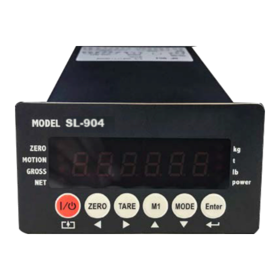
- Page 1 SL-904 PANEL MOUNT INDICATOR USER’S MANUAL www.selletonscales.com...
-
Page 2: Table Of Contents
TABLE OF CONTENTS Safety Precautions Features Specifications Display and Key Descriptions Operating Instructions Rear Panel General Functions Function Settings Parameter Settings 9-10 Calibration Settings 11-14 Check Weighing Configuration Cable Connection Manual 16-18 Troubleshooting Contact Us... -
Page 3: Safety Precautions
SAFETY PRECAUTIONS For safe operation of the weighing indicator, please follow these instructions: ● Calibration inspection and maintenance of the indicator are prohibited by non-pro- fessional staff ● The indicator is a piece of static sensitive equipment; Please cut off power during electrical connections ●... -
Page 4: Features
FEATURES ● LED 6 digit display ● Multiple weighing units: kg/lb/t ● Gross/Tare/Hold/Zero ● Check weighing feature Technical Parameters Hardware construction features ● Power supply: 24vDC ● Load cell excitation voltage: 5vDC±5% ● Load cell number: up to eight 350Ω ●... -
Page 5: Specifications
SPECIFICATIONS FIGURE 1: INDICATOR MEASUREMENTS... -
Page 6: Display And Key Descriptions
DISPLAY AND KEY DESCRIPTION Powers the Indicator On or Off if held for 2 seconds ZERO Zero’s the scale TARE 1. Resets the scale to zero when there is something on the scale (ex. Tare out the weight of a pallet to weigh only the product on it) 2. -
Page 7: Operating Instructions
OPERATING INSTRUCTIONS Power On ● Turn on the power by pressing the power button for 2 seconds. Once on, the scale will flash the voltage and then begin to auto-check and count down from 0-9 sequentially before entering the weighing mode Note: Anything on the scale before powering on will automatically be tared out. -
Page 8: Rear Panel
REAR PANEL Connection definition: Power: POW+ POW- for 24VDC, AC1 AC2 for 220VAC Load cell: EXC+ SEN+ EXC- SEN- SIG+ SIG Serial communications: TXD RXD GND for RS232, A B for RS485 Analog output: Vout Iout GND Relay output: J1 J1 J2 J2 J3 J3 J4 J4 Input: YX1 YX2 YX3 YX4 YXCOM 0vTo exit Tare mode press the TARE key again to enter gross mode and you will see the total weight of the container and the product Note: If you remove the container the scale will show the minus weight of the container... -
Page 9: General Functions
GENERAL FUNCTIONS Function setup and operation procedure: Function Operation Display Remark Enter calibration mode Turn the calibration switch to “ON” 01 CSP Enter function setting 01 FnC Weight mode, press Check weighing setpoint 1.FinAL Weight mode, press parameter setting Enter to test mode 1. -
Page 10: Function Settings
FUNCTION SETTINGS Press at the same time to enter the function settings The screen will display “01 FnC” for function setting Press to display “02 232” for serial port interface Press to display “03 Sq ” for weight comparison procedures Press to display “04 AnL”... -
Page 11: Parameter Settings
INDICATOR PARAMETER SETTINGS To enter parameter settings, follow the procedure below: Press ENTER and MODE at the same time for 2 seconds to enter the function settings Navigate through the settings as shown in the table below by using the arrow keys and return keys as labeled under each indicator button Press the ENTER key to enter/edit the parameter setting... - Page 12 03 Sq Weight Comparison Procedures Function Item Parameter Description Default Batching Mode normal batch less-in weight comparison Control Mode manual start auto for custom Comparison Format gross Start Delay no delay 1 sec delay … 10 sec delay Stable Time no wait 1 sec wait …...
-
Page 13: Calibration Settings
CALIBRATION SETTINGS To enter calibration settings, follow the procedure below: In weighing mode, make sure calibration switch is set to “ON” The display will show “01 CSP” meaning you entered the calibration parameter code ● Press to enter the next step level ●... - Page 14 “01 CSP” Calibration Parameter Code 01 CSP Calibration Parameter Code Function Item Parameter Description Default Unit CSP 01 Decimal point none CSP 02 1 decimal point 2 decimal point 3 decimal point 4 decimal point Division division size CSP 03 Max Capacity Max capacity 010000...
- Page 15 “02 CAL” Calibration 01 CSP In weighing mode set calibration switch to “ON” Calibration press 02 CAL To enter calibration press ZERO Zero calibration press Skip zero calibration press Display zero code 288888 3 seconds SPAN Weight calibration press Skip weight calibration press 01000kg to set the weight Once the weight is stable press...
- Page 16 “03 CUo” Sensitivity Calibration 01 CSP In weighing mode set calibration switch to “ON” Sensitivity Calibration press 03 CUo To enter calibration press ZERO Zero calibration press Skip zero calibration press Auto gather zero code Or press to set zero code 288888 to enter zero calibration Sensitivity calibration press...
-
Page 17: Check Weighing Configuration
CHECK WEIGHING CONFIGURATION Weighing mode press to go enter parameters Display Function 1. FinAL Final value 2. SP1 SP1 value 3. SP2 SP2 value 4. SP3 SP3 value F. FALL Free fall value 6. oVer Over value 7. UndEr Under value 8. -
Page 18: Cable Connection Manual
CABLE CONNECTION MANUAL Power POW+ 24VDC+ POW- 24VDC- 220VAC 220VAC Load cell EXC+ SEN+ EXC- SEN- SIG+ SIG- NOTE: use 4-wire load cell need EXC+ and SEN+ short connect, EXC- and SEN- short connect. Serial Port TXD RS232 transmission RXD RS232 receive GND RS232 GND A RS485 A B RS485 B Analog Output Vout 0~5v voltage, load more than 1kΩ... - Page 19 Relay Output J1 J1 first group relay output J2 J2 second group relay output J3 J3 third group relay output J4 J4 fourth group relay output Relay Output Connecction diagram Common connection diagram Note: Use common connection, put one of J1, J2, J3, J4 short connect.
- Page 20 Input first group input second group input third group input fourth group input YXCOM input common out connect power GND Input Diagram Out connect power input diagram Note: Using out elctric power needs more than 3V battery charge, Out electric power less than 24V.
-
Page 21: Troubleshooting
TROUBLESHOOTING Error Codes Error Reason Solution 1. Overload 1. Reduce the weight 2. Wrong connection with load cell 2. Check load cell connection UUUUUU 3. Load cell has quality problem 3. Inspect load cell; Check the input/output 4. See Q&A section 1.
Need help?
Do you have a question about the SL-904 and is the answer not in the manual?
Questions and answers