Table of Contents
Advertisement
Quick Links
Advertisement
Table of Contents

Subscribe to Our Youtube Channel
Related Manuals for Desa PRV125EDI


Summary of Contents for Desa PRV125EDI
- Page 1 PORTABLE FORCED AIR HEATER OWNER’S MANUAL 125 SIDE PFA/PV 004 Model PRV125EDI IMPORTANT Read and understand this manual before assembling, starting or servicing heater. Improper use of heater can cause serious injury. Keep this manual for future reference.
-
Page 2: Table Of Contents
SECTION PAGE CONTENTS Safety Information ................. 3 Introduction ................... 4 Product Identification ..............4 Unpacking ..................4 Assembly ..................5 Theory of Operation ..............6 Fuels ....................6 Ventilation ..................7 Operation ..................7 Storage ................... 8 Preventative Maintenance Schedule ..........8 Troubleshooting ................ -
Page 3: Safety Information
SAFETY WARNINGS INFORMATION IMPORTANT: Read this owner’s manual carefully and completely before trying to assemble, operate, or service this heater. Improper use of this heater can cause serious injury or death from burns, fire, explosion, electrical shock, and carbon monoxide poisoning. DANGER Carbon monoxide poisoning may lead to death! Carbon Monoxide Poisoning: Early signs of carbon monoxide poisoning... -
Page 4: Introduction
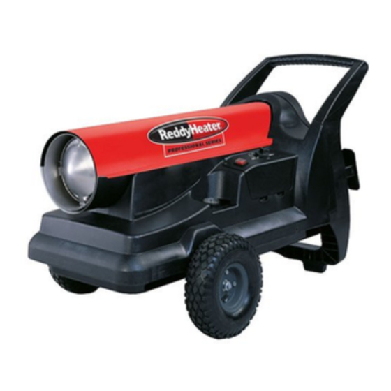
Tank Safety Control Power Cord Reset Button Figure 1 - PRV125EDI UNPACKING 1. Remove all packing items applied to heater for shipment. 2. Remove all items from carton. 3. Check items for shipping damage. If heater is damaged, promptly inform... -
Page 5: Assembly
ASSEMBLY This heater is furnished with wheels, handles, and an interrupter. These items and the mounting hardware are found in the shipping carton. Tools Needed • Medium Phillips Screwdriver • 3/8" Open or Adjustable Wrench • Hammer 1. Slide axle through wheel support frame. Install wheels on axle. IMPORTANT: When installing wheels, point extended hub of wheels toward wheel support frame (see Figure 2). -
Page 6: Theory Of Operation
THEORY OF The Fuel System: The air pump forces air through the air line. The air is then pushed through the burner head nozzle. This air causes fuel to lift from the tank. OPERATION A fine mist of fuel is sprayed into the combustion chamber. The Air System: The motor turns the fan. -
Page 7: Ventilation
VENTILATION WARNING Never use heater without properly installed vent pipe and regulator. You must vent heater to the outdoors. This assures proper combustion and avoids air contamination in the room. A standard 4 inch (10.16 cm) draft regulator is required only if total vertical and horizontal length of the vent pipe exceeds 20 feet (6.1 meters). -
Page 8: Storage
To Stop Heater OPERATION 1. Unplug power cord from outlet. Continued To Restart Heater 1. Wait 2 minutes after stopping heater. 2. Repeat steps under “To Start Heater,” page 7. STORAGE 1. Drain fuel tank. Locate drain plug on underside of fuel tank. Remove drain plug to drain all fuel. -
Page 9: Troubleshooting
TROUBLE- WARNING SHOOTING Never service heater while it is plugged in, operating, or hot. Severe burns and electrical shock can occur. OBSERVED FAULT POSSIBLE CAUSE REMEDY Heater ignites, but Wrong pump pressure See Pump Pressure safety control shuts Adjustment, page 11. off heater after a Dirty air output, air intake See Air Output, Air Intake... -
Page 10: Service Procedures
SERVICE WARNING PROCEDURES Never service heater while it is plugged in, operating, or hot. Severe burns and electrical shock can occur. Upper Shell Removal Upper 1. Remove screws along each Shell side of heater using 5/16" nut-driver. These screws attach upper and lower shells together. -
Page 11: Air Output, Air Intake, And Lint Filters
Air Output, Air Intake, and Lint Filters 1. Remove upper shell (see Air Intake Filter page 10). Filter End 2. Remove filter end cover Cover Fan Guard screws using 5/16" nut- driver. 3. Remove filter end cover. 4. Replace air output and lint filters. -
Page 12: Fuel Filter
Fuel Filter Combustion 1. Remove upper shell (see Fuel Filter Chamber page 10). 2. Remove fan (see page 10). Burner 3. Loosen flare nut using 3/4" Head open-end wrench. Push fuel tube down, away from burner head. Fuel filter is located inside of fuel tube. -
Page 13: Nozzle
Nozzle Combustion Chamber 1. Remove upper shell (see page 10). 2. Remove fan (see page 10). Spark Plug 3. Remove spark plug wire Burner Head Wire from spark plug. 4. Remove spark plug from burner head using 13/16" open-end wrench. 5. -
Page 14: Pump Rotor
Pump Rotor (Procedure if rotor is binding) Pump 1. Remove upper shell (see Blade Plate page 10). 2. Remove filter end cover screws using 5/16" nut- Intake driver. Filter 3. Remove filter end cover Filter End and air filters. Cover 4. -
Page 15: Specifications
SPECIFICATIONS Input Rating (BTU/Hr - K cal/Hr) 88.000/22200 Fuel Use Only Kerosene or No. 1 Fuel Oil Fuel Tank Capacity (U.S. Gallons/Liters) 13.5/51 Fuel Consumption (Gallons Per Hr/Liters Per Hr) 0.66/2.5 Electric Requirements 230V/50HZ Amperage (Normal Run) Hot Air Output (CFM/CMM) 317/8.97 2850 230V/50Hz... -
Page 16: Illustrated Parts Breakdown And Parts List
ILLUSTRATED PARTS BREAKDOWN 28 43... -
Page 17: Wheels And Handles
This list contains replaceable parts used in your heater. When ordering parts, be sure PARTS LIST to provide the correct model and serial numbers (from the model plate), then the part number and description of the desired part. NO. PART NO. DESCRIPTION QTY. -
Page 18: Burner Head Assembly
BURNER HEAD ASSEMBLY KEY PART NO. NO. DESCRIPTION QTY. M23103 Nozzle M10659-1 Nozzle Seal M10809-1 Nozzle Seal Spring M8882 Nozzle Seal Sleeve M51098-01 Burner Head Body M5976 Male Connector 079685-01 Male Connector 079722-01 Fuel Tube/Fuel Filter Assy. M10962-2 Spark Plug M50050 Ignition Boot MOTOR... - Page 19 NOTES...
- Page 20 099665-01 REV. C 8/92...
Need help?
Do you have a question about the PRV125EDI and is the answer not in the manual?
Questions and answers