Table of Contents
Advertisement
Quick Links
V525
User Guide and
Hardware Maintenance Manual
Machine Type (MT):
10N7, 10N8
Energy Star MT:
10N7, 10N8
Overview
Locations of indicators,
connectors, and
controls provided on
your computer
Replacing hardware
Locations of the
replaceable parts on
your computer
Specifications
Specifications of your
computer
Replacing CRUs
Replacing instructions
for Customer
Replaceable Units
(CRUs)
Computer locks
Locking devices for
your computer
Replacing FRUs
Replacing instructions
for Field Replaceable
Units (FRUs) (for
technicians only)
Advertisement
Table of Contents

Related Manuals for Lenovo V525


Summary of Contents for Lenovo V525
- Page 1 V525 User Guide and Hardware Maintenance Manual Machine Type (MT): 10N7, 10N8 Energy Star MT: 10N7, 10N8 Overview Specifications Computer locks Locations of indicators, Specifications of your Locking devices for connectors, and computer your computer controls provided on your computer...
-
Page 2: Table Of Contents
Contents Overview .........3 Replacing a PCI Express card ........30 Replacing the Wi-Fi card ...........31 Front view ............... 3 Replacing the M.2 solid-state drive ......33 Rear view ................ 4 Replacing the M.2 solid-state drive bracket ..35 System board ..............6 Replacing the power supply assembly ....36 Machine type and model label ........ -
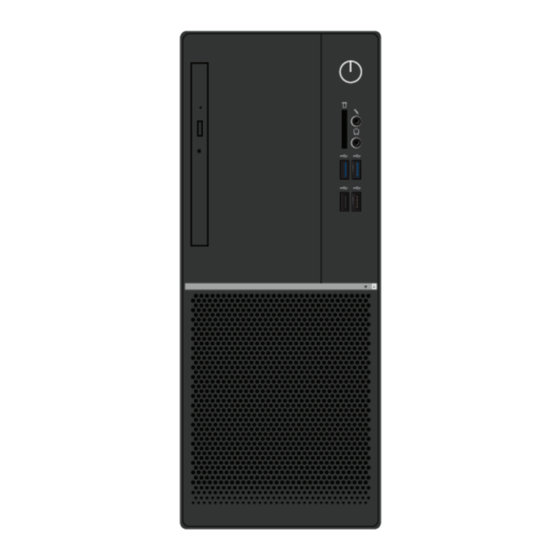
Page 3: Overview
Overview Front view Note Your computer model might look slightly different from the illustration. Optical drive eject/close button Used to eject the tray of the optical drive. After you insert a disc into the tray, push the tray backward to close it. Optical drive status indicator This indicator is on when the optical drive is in use. -
Page 4: Rear View
Rear view Note Your computer model might look slightly different from the illustration. Microphone connector Used to connect a microphone to your computer when you want to record sound or use speech recognition software. HDMI™-out connector Used to send audio and video signals from the computer to another audio or video device, such as a high-performance monitor. - Page 5 Serial connector Used to connect an external modem, a serial printer, or other devices that use a serial connector. Ethernet connector Used to connect an Ethernet cable for network access. Cable lock slots (2) Used to secure a cable lock. PCI-Express card area To improve the operating performance of the computer, you can connect PCI-Express cards into this area.
-
Page 6: System Board
System board Note Front view Rear view for additional component descriptions. 4-pin power connector Microprocessor fan connector Coin-cell battery Buzzer Power button board connector Front USB 2.0 connector (Card reader connector) Auxiliary fan connector 1 10-pin power connector M.2 solid-state drive slot SATA 3.0 connectors (2) Thermal sensor connector SATA power connector... - Page 7 Cover presence switch connector (Intrusion switch connector) M.2 Wi-Fi card slot PCI Express x1 card slot PCI Express x16 graphics card slot System fan connector Microprocessor socket Memory slot (DIMM1) Memory slot (DIMM2) Overview...
-
Page 8: Machine Type And Model Label
Machine type and model label The machine type and model label identifies the computer. When you contact Lenovo for help, the machine type and model information helps support technicians to identify the computer and provide faster service. The machine type and model label is attached on the side of the computer as shown. -
Page 9: Specifications
Specifications Power supply 180 watt automatic voltage-sensing power supply Storage drives • 3.5-inch storage drive • 2.5-inch storage drive • M.2 solid-state drive Video features The integrated graphics card supports the following: • HDMI-out connector • VGA-out connector Audio features The integrated audio card supports the following: •... - Page 10 Network features • Ethernet LAN • Wireless LAN (optional) • Bluetooth (optional) Physical dimensions • Width: 145.0 mm (5.7 inches) • Height: 366.0 mm (14.4 inches) • Depth: 293.2 mm (11.5 inches) Weight (without the package) Maximum configuration as shipped: 6.9 kg (15.1 lb) Specifications...
-
Page 11: Computer Locks
The cable lock also locks the buttons used to open the computer cover. This is the same type of lock used with many notebook computers. You can order such a cable lock directly from Lenovo by searching for Kensington at: http://www.lenovo.com/ support. Attaching a cable lock A cable lock can be used to secure devices, such as the keyboard and the mouse, by locking the device cables to the computer. -
Page 12: Replacing Hardware
• In most areas of the world, Lenovo requires the return of defective CRUs. Information about this will come with the CRU or will come a few days after the CRU arrives. -
Page 13: Knowing Replaceable Parts
CRU. Optional-service CRUs can be removed and installed by users or, during the warranty period, by a Lenovo service technician. Field Replaceable Units (FRUs) FRUs are computer parts that a trained technician can upgrade or replace. -
Page 14: Crus And Frus Locations
CRUs and FRUs locations Refer to the following illustrations to check the locations of CRUs and FRUs within the computer. Note Some of the following parts are optional on some models. Self-service CRU Computer cover p. 19 Coin-cell battery p. 29 Memory module p. - Page 15 Optional-service CRU Heat sink and fan assembly p. 28 Wi-Fi card p. 31 Wi-Fi card shield p. 31 Power supply assembly p. 36 Replacing hardware...
- Page 16 Rear fan p. 49 Microprocessor p. 47 System board p. 51 Power button board p. 44 Optical drive cable Card reader p. 46 Wi-Fi antennas (2) p. 42 Rear Wi-Fi antenna cover p. 42 Thermal sensor p. 41 Storage drive cable Front fan p.
-
Page 17: Replacing Crus
Replacing CRUs Before replacing CRUs To check the locations of CRUs, see CRUs and FRUs locations. Do not open your computer or attempt any repairs before reading the Important Attention Product Information Guide. Before replacing a CRU, click the illustration of the part to check the brief procedures. Computer cover Front bezel Optical drive... - Page 18 Wi-Fi card M.2 solid-state drive M.2 solid-state drive Power supply assembly bracket To replace a component that is not in the list above, contact a Lenovo service Note technician. The support phone numbers are available at: http://www.lenovo.com/ support/phone Replacing CRUs...
-
Page 19: Removing The Computer Cover
Removing the computer cover Do not open your computer or attempt any repairs before reading the Important Attention Product Information Guide. Before you open the computer cover, turn off the computer and wait several minutes Caution until the computer is cool. Remove any media from the drives and turn off all connected devices and the computer. -
Page 20: Replacing The Front Bezel
Replacing the front bezel Do not open your computer or attempt any repairs before reading the Important Attention Product Information Guide. Remove the computer cover. For details, see Removing the computer cover. Replace the front bezel. Complete the replacement. For details, see Completing the parts replacement. ... -
Page 21: Replacing The Optical Drive
Replacing the optical drive Do not open your computer or attempt any repairs before reading the Important Attention Product Information Guide. Remove the computer cover. For details, see Removing the computer cover. Remove the front bezel. For details, see Replacing the front bezel. Disconnect the signal cable and the power cable from the optical drive. -
Page 22: Replacing The Optical Drive Bracket
Replacing the optical drive bracket Do not open your computer or attempt any repairs before reading the Important Attention Product Information Guide. Remove the computer cover. For details, see Removing the computer cover. Remove the front bezel. For details, see Replacing the front bezel. ... -
Page 23: Pivoting The Drive Bay Assembly Upward And Downward
Pivoting the drive bay assembly upward and downward Do not open your computer or attempt any repairs before reading the Important Attention Product Information Guide. Remove the computer cover. For details, see Removing the computer cover. Remove the front bezel. For details, see Replacing the front bezel. ... -
Page 24: Replacing The Storage Drive
Replacing the storage drive Do not open your computer or attempt any repairs before reading the Important Attention Product Information Guide. Replacing the 3.5-inch storage drive Remove the computer cover. For details, see Removing the computer cover. Remove the front bezel. For details, see Replacing the front bezel. ... -
Page 25: Replacing The 2.5-Inch Storage Drive
• 3.5-inch secondary storage drive Connect the signal cable and the power cable to the new 3.5-inch storage drive. Reinstall the removed parts. To complete the replacement, see Completing the parts replacement. Replacing the 2.5-inch storage drive Remove the storage converter with the 2.5-inch storage drive. See Replacing the 3.5-inch storage drive. ... -
Page 26: Replacing A Memory Module
Replacing a memory module Do not open your computer or attempt any repairs before reading the Important Attention Product Information Guide. Ensure that you follow the installation order for memory modules shown in the following figure. Remove the computer cover. For details, see Removing the computer cover. ... - Page 27 Replace a memory module. Reinstall the removed parts. To complete the replacement, see Completing the parts replacement. Replacing CRUs...
-
Page 28: Replacing The Heat Sink And Fan Assembly
Replacing the heat sink and fan assembly Do not open your computer or attempt any repairs before reading the Important Attention Product Information Guide. Remove the computer cover. For details, see Removing the computer cover. Remove the front bezel. For details, see Replacing the front bezel. ... -
Page 29: Replacing The Coin-Cell Battery
Replacing the coin-cell battery Do not open your computer or attempt any repairs before reading the Important Attention Product Information Guide. Your computer has a special type of memory that maintains the date, time, and settings for built- in features, such as parallel connector assignments (configurations). A coin-cell battery keeps this information active when you turn off the computer. -
Page 30: Replacing A Pci Express Card
Replacing a PCI Express card Do not open your computer or attempt any repairs before reading the Important Attention Product Information Guide. Remove the computer cover. For details, see Removing the computer cover. Remove the front bezel. For details, see Replacing the front bezel. ... -
Page 31: Replacing The Wi-Fi Card
Replacing the Wi-Fi card Do not open your computer or attempt any repairs before reading the Important Attention Product Information Guide. Remove the computer cover. For details, see Removing the computer cover. Remove the front bezel. For details, see Replacing the front bezel. Pivot the drive bay assembly upward. - Page 32 • Type 2 Reinstall the removed parts. To complete the replacement, see Completing the parts replacement. Replacing CRUs...
-
Page 33: Replacing The M.2 Solid-State Drive
Replacing the M.2 solid-state drive Do not open your computer or attempt any repairs before reading the Important Attention Product Information Guide. Remove the computer cover. For details, see Removing the computer cover. Remove the front bezel. For details, see Replacing the front bezel. ... - Page 34 • Type 2 Reinstall the removed parts. To complete the replacement, see Completing the parts replacement. Replacing CRUs...
-
Page 35: Replacing The M.2 Solid-State Drive Bracket
Replacing the M.2 solid-state drive bracket Do not open your computer or attempt any repairs before reading the Important Attention Product Information Guide. Remove the computer cover. For details, see Removing the computer cover. Remove the front bezel. For details, see Replacing the front bezel. ... -
Page 36: Replacing The Power Supply Assembly
Replacing the power supply assembly Do not open your computer or attempt any repairs before reading the Important Attention Product Information Guide. Although there are no moving parts in your computer after the power cord has been disconnected, the following warnings are required for your safety and proper Underwriters Laboratories (UL) certification. Never remove the cover on a power supply or any part that has the following label Caution attached. -
Page 37: Completing The Parts Replacement
Completing the parts replacement After completing the installation or replacement for all parts, reinstall the computer cover and reconnect the cables. To reinstall the computer cover and reconnect the cables to your computer, do the following: Ensure that all components have been reassembled correctly and that no tools or loose screws are left inside your computer. -
Page 38: Replacing Frus
• Replace an FRU only with another FRU of the correct model. When you replace an FRU, ensure that the model of the machine and the FRU part number are correct by referring to the website http://www.lenovo.com/serviceparts-lookup. • An FRU should not be replaced because of a single, unreproducible failure. - Page 39 Power button board Card reader Microprocessor Rear fan Cover presence switch System board To replace a component that is not in the list above, contact a Lenovo service Note technician. The support phone numbers are available at: http://www.lenovo.com/ support/phone Replacing FRUs...
-
Page 40: Replacing The Front Fan
Replacing the front fan Do not open your computer or attempt any repairs before reading the Important Attention Product Information Guide. Remove the computer cover. For details, see Removing the computer cover. Remove the front bezel. For details, see Replacing the front bezel. Pivot the drive bay assembly upward. -
Page 41: Replacing The Thermal Sensor
Replacing the thermal sensor Do not open your computer or attempt any repairs before reading the Important Attention Product Information Guide. Remove the computer cover. For details, see Removing the computer cover. Remove the front bezel. For details, see Replacing the front bezel. Pivot the drive bay assembly upward. -
Page 42: Replacing The Wi-Fi Antennas
Replacing the Wi-Fi antennas Do not open your computer or attempt any repairs before reading the Important Attention Product Information Guide. Remove the computer cover. For details, see Removing the computer cover. Remove the front bezel. For details, see Replacing the front bezel. Disconnect the Wi-Fi antenna cables from the Wi-Fi card. - Page 43 • Rear Wi-Fi antenna Connect the new Wi-Fi antenna cables to the Wi-Fi card. For details, see Replacing the Wi-Fi card. Reinstall the removed parts. To complete the replacement, see Completing the parts replacement. Replacing FRUs...
-
Page 44: Replacing The Power Button Board
Replacing the power button board Do not open your computer or attempt any repairs before reading the Important Attention Product Information Guide. Remove the computer cover. For details, see Removing the computer cover. Remove the front bezel. For details, see Replacing the front bezel. ... - Page 45 Connect the new power button board cable to the system board. Reinstall the removed parts. To complete the replacement, see Completing the parts replacement. Replacing FRUs...
-
Page 46: Replacing The Card Reader
Replacing the card reader Do not open your computer or attempt any repairs before reading the Important Attention Product Information Guide. Remove the computer cover. For details, see Removing the computer cover. Remove the front bezel. For details, see Replacing the front bezel. Remove the power button board. -
Page 47: Replacing The Microprocessor
Replacing the microprocessor Do not open your computer or attempt any repairs before reading the Important Attention Product Information Guide. The heat sink and microprocessor might be very hot. Before you open the Caution computer cover, turn off the computer and wait several minutes until the computer is cool. - Page 48 Route all the cables that you disconnected from the system board, and then reconnect the cables to the system board. See System board. Reinstall the removed parts. To complete the replacement, see Completing the parts replacement. Replacing FRUs...
-
Page 49: Replacing The Rear Fan
Replacing the rear fan Do not open your computer or attempt any repairs before reading the Important Attention Product Information Guide. Remove the computer cover. For details, see Removing the computer cover. Remove the front bezel. For details, see Replacing the front bezel. Pivot the drive bay assembly upward. -
Page 50: Replacing The Cover Presence Switch
Replacing the cover presence switch Do not open your computer or attempt any repairs before reading the Important Attention Product Information Guide. Remove the computer cover. For details, see Removing the computer cover. Remove the front bezel. For details, see Replacing the front bezel. ... -
Page 51: Replacing The System Board
Replacing the system board Do not open your computer or attempt any repairs before reading the Important Attention Product Information Guide. Remove the computer cover. For details, see Removing the computer cover. Remove the front bezel. For details, see Replacing the front bezel. Remove the front I/O bracket. - Page 52 Replace the system board. • The numbers in the following figure show the locations of the screws instead of Notes the removing and reinstalling order of the screws. • Handle the system board carefully by its edges. Route all the cables that you disconnected from the failing system board, and then reconnect the cables to the new system board.
-
Page 53: Notices & Trademarks
Any warranties in certain transactions, therefore, this reference to a Lenovo product, program, or service statement may not apply to you. is not intended to state or imply that only that Lenovo product, program, or service may be used. -
Page 54: Trademarks
Web sites. The materials at those Web Multimedia Interface are trademarks or registered sites are not part of the materials for this Lenovo trademarks of HDMI Licensing LLC in the United product, and use of those Web sites is at your own States and other countries.
Need help?
Do you have a question about the V525 and is the answer not in the manual?
Questions and answers