
Subscribe to Our Youtube Channel
Related Manuals for Premium PWM5010M

Summary of Contents for Premium PWM5010M
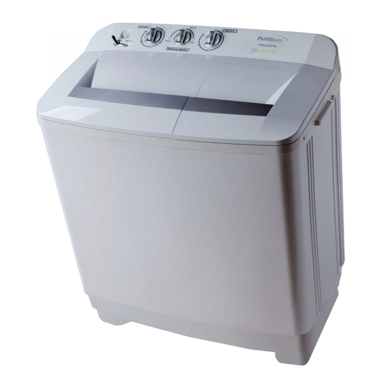
- Page 1 SERVICE MANUAL TWIN TUB WASHING MACHINE PWM5010M PWM6010M PWM8010PM PWM1010PM PWM1210PM...
-
Page 2: Table Of Contents
TABLE OF CONTENES 1.SAFETY PRECAUTION 1. Safety precaution Do not dismantle the machine Do not install the machine in Do not place inflammable Do not spray water directly to 2. Introduction of product by yourself. damp or rainy environment to materials like burning candle, the machine. -
Page 3: Safety Precaution
SAFETY PRECAUTION 2. INTRODUCTION OF PRODUCTS 3.TROUBLE SHOOTING 3.1 Malfuction and solution 2.1 Name of parts Symptom Possible reason Solution Control panel Drain hose a. Laundry is much more than rated a. Reduce the laundry till the (For upper drain only) washing capacity. -
Page 4: Trouble Shooting
3.TROUBLE SHOOTING 3.TROUBLE SHOOTING Symptom Symptom Possible reason Solution Possible reason Solution Spin motor winding is burned. If the motor is damaged a. There is things like coins, buttons a. Dismantle the pulsator and take Fuse is burned. because of water leakage under the pulsator. -
Page 5: Can Not Wash(Motor Does Not Rotate)
3.TROUBLE SHOOTING 3.TROUBLE SHOOTING 3.2 Fault tree Symptom Possible reason Solution 1. Can not wash (motor does not rotate) a. Safety switch contact does not a. Adjust the safety switch contact. Can not wash open when open the spin cover. b. -
Page 6: Spin Tub Can Not Rotate
3.TROUBLE SHOOTING 3.TROUBLE SHOOTING 2. Spin tub can not rotate 3. No drain or unsmooth drain Can not drain Can not spin for lower drain function only Whether the drain Whether the spin Replace the spin motor Put down the drain hose hose is put down motor is well for upper drain function only... -
Page 7: Dismantling Ways Of Main Parts
4.DISMANTLING WAYS OF MAIN PARTS 4.DISMANTLING WAYS OF MAIN PARTS Operation step Operation step Picture Picture 4. Remove the pulsator 1. Remove the knobs a. Unscrew the pulsator screw. a.Take out the knobs directly b. Draw out the pulsator with because knobs are inserted into the control panel. -
Page 8: Remove The Spin Tub
4.DISMANTLING WAYS OF MAIN PARTS 4.DISMANTLING WAYS OF MAIN PARTS Operation step Operation step Picture Picture 7.Remove the spin tub 10. Remove the capacitor a. Unscrew the fixing screw under the tub with a socket wrench. a.Hold firm the capacitor then b. -
Page 9: Electronic Components
5.ELECTRONIC COMPONENTS 5.ELECTRONIC COMPONENTS Operation step Operation step Picture Picture 1. Self-test method of wash 4. Self-test method of safety switch timer Turn the wash timer to work The safety switch should be in condition. Use a multimeter to closure state when the spin tub measure the connection and cover is closed. -
Page 10: Circuit Diagram
5.ELECTRONIC COMPONENTS 6.CIRCUIT DIAGRAM Operation step Picture b. Check whether the motor resistance is normal in the condition of no water condition: Use a multimeter to measure the resistance of the three leads, and name them R1, R2, R3.Only the “R1+R2=R3”...
Need help?
Do you have a question about the PWM5010M and is the answer not in the manual?
Questions and answers