Table of Contents
Advertisement
Quick Links
GA-K8N51PVMT-9
AMD Socket 939 Processor Motherboard
User's Manual
Rev. 1003
12ME-51PVMT9-1003R
* The WEEE marking on the product indicates this product must not be disposed of with user's other household waste
and must be handed over to a designated collection point for the recycling of waste electrical and electronic equipment!!
* The WEEE marking applies only in European Union's member states.
Advertisement
Table of Contents

Related Manuals for Gigabyte GA-K8N51PVMT-9

Summary of Contents for Gigabyte GA-K8N51PVMT-9
- Page 1 GA-K8N51PVMT-9 AMD Socket 939 Processor Motherboard User's Manual Rev. 1003 12ME-51PVMT9-1003R * The WEEE marking on the product indicates this product must not be disposed of with user's other household waste and must be handed over to a designated collection point for the recycling of waste electrical and electronic equipment!!
- Page 3 Gigabyte's prior written permission. Specifications and features are subject to change without prior notice. Product Manual Classification In order to assist in the use of this product, Gigabyte has categorized the user manual in the following: For detailed product information and specifications, please carefully read the "Product User Manual".
-
Page 4: Table Of Contents
Table of Contents GA-K8N51PVMT-9 Motherboard Layout ... 6 Block Diagram ... 7 Chapter 1 Hardware Installation ... 9 Considerations Prior to Installation ... 9 Feature Summary ... 10 Installation of the CPU and Fan Heat Sink ... 12 1-3-1 Installation of the CPU ... 12 1-3-2 Installation of the Fan Heat Sink ... - Page 5 Chapter 3 Drivers Installation ... 49 Install Chipset Drivers ... 49 Software Application ... 50 Software Information ... 50 Hardware Information ... 51 Contact Us ... 51 Chapter 4 Appendix ... 53 Unique Software Utilities ... 53 4-1-1 EasyTune 5 Introduction ... 53 4-1-2 Xpress Recovery Introduction ...
-
Page 6: Ga-K8N51Pvmt-9 Motherboard Layout
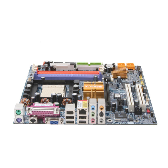
GA-K8N51PVMT-9 Motherboard Layout KB_MS ATX_12V AUDIO1 F_AUDIO AUDIO2 PCIE_16 PCIE_1 VITESSE 8201 CD_IN COMA CODEC SPDIF_IO CPU_FAN Socket 939 nVIDIA ® GeForce 6150 BIOS PCI1 VT6307 PCI2 F1_1394 SYS_FAN - 6 - nVIDIA ® nForce 430 F_PANEL F_USB1 F_USB2 PWR_LED... -
Page 7: Block Diagram
Block Diagram PCI-ECLK (100MHz) TV Out PCI Express x 16 PCI Express Bus PCI-ECLK (100MHz) 1 PCI Express x 1 VITESSE LAN RJ45 PCI Bus VT6307 2 IEEE1394 2 PCI PCICLK (33MHz) AMD K8 Socket 939 Hyper Transport nVIDIA ® GeForce 6150 8201 nVIDIA... - Page 8 - 8 -...
-
Page 9: Chapter 1 Hardware Installation
2. Damage as a result of violating the conditions recommended in the user manual. 3. Damage due to improper installation. 4. Damage due to use of uncertified components. 5. Damage due to use exceeding the permitted parameters. 6. Product determined to be an unofficial Gigabyte product. - 9 - Hardware Installation... -
Page 10: Feature Summary
For example, 4 GB of memory size will instead be shown as 3.xxGB memory during system startup. GA-K8N51PVMT-9 Motherboard 64 / 64 FX processor (K8) GeForce 6150 ®... - Page 11 (Note 2) Whether the CPU Smart FAN Control function is supported will depend on the CPU you install. For more detailed information please check at the FAQ section on GIGABYTE's website. (Note 3) EasyTune functions may vary depending on different motherboards.
-
Page 12: Installation Of The Cpu And Fan Heat Sink
CPU and gently press the metal lever back into its original position. Please use extra care when installing the CPU. The CPU will not fit if positioned incorrectly. Rather than applying force, please change the positioning of the CPU. GA-K8N51PVMT-9 Motherboard - 12 -... -
Page 13: Installation Of The Fan Heat Sink
1-3-2 Installation of the Fan Heat Sink Fig.1 Before installing the fan heat sink, please first add an even layer of heat sink paste on the surface of the CPU. Install all the fan heat sink components (Please refer to the heat sink manual for detailed installation instructions). -
Page 14: Installation Of Memory
DIMM socket. Then push it down. Fig.2 Close the plastic clip at both edges of the DIMM sockets to lock the DIMM module. Reverse the installation steps when you wish to remove the DIMM module. GA-K8N51PVMT-9 Motherboard Notch - 14 -... - Page 15 Dual Channel Memory Configuration The GA-K8N51PVMT-9 supports the Dual Channel Technology. When the Dual Channel Technology is activated, the bandwidth of memory bus will be double the original one. Due to CPU limitation, if you want to operate the Dual Channel Technology, please follow the guidelines below for Dual Channel memory configuration.
-
Page 16: Installation Of Expansion Cards
Power on the computer, if necessary, setup BIOS utility of expansion card from BIOS. Install related driver from the operating system. Installing a PCI Express x 16 expansion card: GA-K8N51PVMT-9 Motherboard Please carefully pull out the small white- drawable bar at the end of the PCI Ex- press x 16 slot when you try to install/ uninstall the VGA card. -
Page 17: I/O Back Panel Introduction
I/O Back Panel Introduction PS/2 Keyboard and PS/2 Mouse Connector To install a PS/2 port keyboard and mouse, plug the mouse to the upper port (green) and the keyboard to the lower port (purple). Parallel Port The parallel port allows connection of a printer, scanner and other peripheral devices. TV Out Port (Note 1) HDTV, NTSC / PAL TV and Projector etc. - Page 18 Surround Speaker Out (Rear Speaker Out) jack. Side Speaker Out The default Side Speaker Out jack. Surround side speakers can be connected to Side Speaker Out jack. (Note 2) You can use audio software to configure 2-/4-/6-/8-channel audio functioning. GA-K8N51PVMT-9 Motherboard - 18 -...
-
Page 19: Connectors Introduction
Connectors Introduction 1) ATX_12V 2) ATX (Power Connector) 3) CPU_FAN 4) SYS_FAN 5) FDD 6) IDE1 / IDE2 7) SATAII0_1 / SATAII2_3 8) PWR_LED 9) BATTERY 10) F_PANEL 11) F_AUDIO 12) CD_IN 13) F_USB1 / F_USB2 14) F1_1394 15) SPDIF_IO 16) COMA 17) CLR_CMOS 18) C I... - Page 20 If you use a 24-pin ATX power supply, please remove the small cover on the power connector on the motherboard before plugging in the power cord; otherwise, please do not remove it. GA-K8N51PVMT-9 Motherboard Pin No. Pin No.
- Page 21 3/4) CPU_FAN / SYS_FAN (Cooler Fan Power Connector) The cooler fan power connector supplies a +12V power voltage via a 3-pin power connector and possesses a foolproof connection design. Most coolers are designed with color-coded power connector wires. A red power connector wire indicates a positive connection and requires a +12V power voltage.
- Page 22 7) SATAII0/1/2/3 (SATA 3Gb/s Connectors, Controlled by nForce 430) SATA 3Gb/s can provide up to 300MB/s transfer rate. Please refer to the BIOS setting for the SATA 3Gb/s and install the proper driver in order to work properly. GA-K8N51PVMT-9 Motherboard IDE2 IDE1 Pin No.
- Page 23 8) PWR_LED PWR_LED is connect with the system power indicator to indicate whether the system is on/off. It will blink when the system enters suspend mode. 9) BATTERY Pin No. Definition MPD+ MPD- MPD- Danger of explosion if battery is incorrectly replaced. Replace only with the same or equivalent type recommended by the manufacturer.
-
Page 24: Front Panel Jumper
F_PANEL connector according to the pin assignment below. HD (IDE Hard Disk Active LED) SPEAK (Speaker Connector) RES (Reset Switch) PW (Power Switch) MSG (Message LED/Power/Sleep LED) GA-K8N51PVMT-9 Motherboard Speaker Connector Message LED/ Power Power/ Sleep LED... - Page 25 11) F_AUDIO (Front Audio Panel Connector) This connector supports either HD (High Definition) or AC97 front panel audio module. If you wish to use the front audio function, connect the front panel audio module to this connector. Check the pin assignments carefully while you connect the front panel audio module.
- Page 26 Check the pin assignment carefully while you connect the IEEE1394 cable, incorrect connection between the cable and connector will make the device unable to work or even damage it. For optional IEEE1394 cable, please contact your local dealer. GA-K8N51PVMT-9 Motherboard Pin No. Definition...
- Page 27 15) SPDIF_IO (SPDIF In/Out) The SPDIF output is capable of providing digital audio to external speakers or compressed AC3 data to an external Dolby Digital Decoder. Use this feature only when your stereo system has digital input function. Use SPDIF IN feature only when your device has digital output function. Be careful with the polarity of the SPDIF_IO connector.
- Page 28 1-2 pin. Default doesn't include the jumper to avoid improper use of this header. 18) CI (Chassis Intrusion, Case Open) This 2-pin connector allows your system to detect if the chassis cover is removed. You can check the "Case Open" status in BIOS Setup. GA-K8N51PVMT-9 Motherboard Open: Normal Short: Clear CMOS Pin No.
-
Page 29: Chapter 2 Bios Setup
BIOS needs to be reset to its original settings. If you wish to upgrade to a new BIOS, either Gigabyte's Q-Flash or @BIOS utility can be used. Q-Flash allows the user to quickly and easily update or backup BIOS without entering the operating system. -
Page 30: The Main Menu (For Example: Bios Ver. : F1)
Fail-Safe Defaults indicates the value of the system parameters which the system would be in safe configuration. Load Optimized Defaults Optimized Defaults indicates the value of the system parameters which the system would be in best performance configuration. GA-K8N51PVMT-9 Motherboard Load Fail-Safe Defaults Load Optimized Defaults Set Supervisor Password Set User Password Save &... - Page 31 Set Supervisor Password Change, set, or disable password. It allows you to limit access to the system and Setup, or just to Setup. Set User Password Change, set, or disable password. It allows you to limit access to the system. Save &...
-
Page 32: Standard Cmos Features
Allows BIOS to automatically detect IDE devices during POST(default) None Select this if no IDE devices are used and the system will skip the automatic detection step and allow for faster system start up. GA-K8N51PVMT-9 Motherboard Standard CMOS Features Tue, Sep 13 2005 22:31:24... - Page 33 Access Mode Use this to set the access mode for the hard drive. The two options are: Large/Auto(default:Auto) Capacity Capacity of currently installed hard drive. Hard drive information should be labeled on the outside drive casing. Enter the appropriate option based on this information.
-
Page 34: Advanced Bios Features
Disabled BIOS will not search for the type of floppy disk drive by track number. Note that there will not be any warning message if the drive installed is 360K. (Default value) GA-K8N51PVMT-9 Motherboard Advanced BIOS Features [Press Enter] [Floppy]... - Page 35 Password Check System The system can not boot and can not access to Setup page will be denied if the correct password is not entered at the prompt. Setup The system will boot, but access to Setup will be denied if the correct password is not entered at the prompt.
-
Page 36: Integrated Peripherals
Enable SATAII 1 1st SATA RAID function. Disabled Disable this function. (Default value) SATA-II 1 Secondary RAID Enabled Enable SATAII 1 2nd SATA RAID function. Disabled Disable this function. (Default value) GA-K8N51PVMT-9 Motherboard Integrated Peripherals [Press Enter] [Enabled] [Enabled] [Auto] [Auto] [Enabled] [Enabled] [V1.1+V2.0]... - Page 37 SATA-II 2 Primary RAID Enabled Enable SATAII 2 1st SATA RAID function. Disabled Disable this function. (Default value) SATA-II 2 Secondary RAID Enabled Enable SATAII 2 2nd SATA RAID function. Disabled Disable this function. (Default value) On-Chip IDE Channel0 Enabled Enable onboard 1st channel IDE port.
- Page 38 Parallel Port Mode Using Parallel port as Standard Parallel Port. (Default value) Using Parallel port as Enhanced Parallel Port. Using Parallel port as Extended Capabilities Port. ECP+EPP Using Parallel port as ECP and EPP mode. GA-K8N51PVMT-9 Motherboard - 38 -...
-
Page 39: Power Management Setup
Power Management Setup CMOS Setup Utility-Copyright (C) 1984-2005 Award Software ACPI Suspend Type Soft-Off by Power button PME Event Wake Up Modem Ring On USB Resume from Suspend Power-On by Alarm x Day of Month Alarm x Time (hh:mm:ss) Alarm Power On By Keyboard x KB Power ON Password Power On By Mouse... - Page 40 When AC-power back to the system, the system will be in "Off" state. (Default value) Full-On When AC-power back to the system, the system always in "On" state. Memory When AC-power back to the system, the system will return to the Last state before AC-power off. GA-K8N51PVMT-9 Motherboard - 40 -...
-
Page 41: Pnp/Pci Configurations
PnP/PCI Configurations CMOS Setup Utility-Copyright (C) 1984-2005 Award Software PCI 1 IRQ Assignment PCI 2 IRQ Assignment : Move Enter: Select F5: Previous Values PCI 1 IRQ Assignment Auto 3,4,5,7,9,10,11,12,14,15 PCI 2 IRQ Assignment Auto 3,4,5,7,9,10,11,12,14,15 PnP/PCI Configurations [Auto] [Auto] +/-/PU/PD: Value F10: Save ESC: Exit... -
Page 42: Pc Health Status
F Monitor CPU temperature at 90 Disabled Disable this function. (Default value) System/CPU FAN Stop Warning Disabled Disable System/CPU fan stop warning function. (Default value) Enabled Enable System/CPU fan stop warning function. GA-K8N51PVMT-9 Motherboard PC Health Status [Disabled] C/89 C/113 3245 RPM 3245 RPM [Disabled]... - Page 43 CPU temperature. Users can adjust the fan speed with Easy Tune based on their requirements. (Note) Whether the CPU Smart FAN Control function is supported will depend on the CPU you install. For more detailed information please check at the FAQ section on GIGABYTE's website. - 43 - BIOS Setup...
-
Page 44: Frequency/Voltage Control
Select the options can enhance the VGA graphics card bandwidth to get higher performance. Auto Set Robust Graphics Booster to Auto. (Default value) Fast Set Robust Graphics Booster to Fast. Turbo Set Robust Graphics Booster to Turbo. GA-K8N51PVMT-9 Motherboard Frequency/Voltage Control [200.0] [100Mhz] [Default] [RGB] [Disabled]... -
Page 45: Load Fail-Safe Defaults
Load Fail-Safe Defaults CMOS Setup Utility-Copyright (C) 1984-2005 Award Software Standard CMOS Features Advanced BIOS Features Integrated Peripherals Power Management Setup PnP/PCI Configurations PC Health Status Frequency/Voltage Control Esc: Quit F8: Q-Flash Fail-Safe defaults contain the most appropriate values of the system parameters that allow minimum system performance. -
Page 46: Set Supervisor/User Password
Setup Menu. If you select "Setup" at "Password Check" in Advance BIOS Features Menu, you will be prompted only when you try to enter Setup. GA-K8N51PVMT-9 Motherboard Load Fail-Safe Defaults Load Optimized Defaults... -
Page 47: Save & Exit Setup
2-11 Save & Exit Setup CMOS Setup Utility-Copyright (C) 1984-2005 Award Software Standard CMOS Features Advanced BIOS Features Integrated Peripherals Power Management Setup PnP/PCI Configurations PC Health Status Frequency/Voltage Control Esc: Quit F8: Q-Flash Type "Y" will quit the Setup Utility and save the user setup value to RTC CMOS. Type "N"... - Page 48 GA-K8N51PVMT-9 Motherboard - 48 -...
-
Page 49: Chapter 3 Drivers Installation
Chapter 3 Drivers Installation Pictures below are shown in Windows XP. Insert the driver CD-title that came with your motherboard into your CD-ROM drive, the driver CD-title will auto start and show the installation guide. If not, please double click the CD-ROM device icon in "My computer", and execute the Setup.exe. -
Page 50: Software Application
Software Application This page displays all the tools that GIGABYTE developed and some free software. You can click an item to install it. Software Information This page lists the contents of software and drivers in this CD-title. GA-K8N51PVMT-9 Motherboard - 50 -... -
Page 51: Hardware Information
Hardware Information This page lists all device you have for this motherboard. Contact Us Please see the last page for details. - 51 - Drivers Installation... - Page 52 GA-K8N51PVMT-9 Motherboard - 52 -...
-
Page 53: Chapter 4 Appendix
Display screen Function display LEDs GIGABYTE Logo Help button Exit or Minimize button (Note) EasyTune 5 functions may vary depending on different motherboards. (Note) Description Enters the Overclocking setting page Enters the C.I.A./2 and M.I.B./2 setting page Enters the Smart-Fan setting page... -
Page 54: Xpress Recovery Introduction
Once you have completed this step, subsequent access to Xpress Recovery can also function by pressing the F9 key during computer power on. Verifying DMI Pool Data Boot from CD: Xpress Recovery V1.0 (C) Copy Right 2003. GIGABYTE Technology CO. , Ltd. 1. Execute Backup Utility 2. Execute Restore Utility 3. Remove Backup Image 4. - Page 55 Press DEL to enter SETUP / Q-Flash, F9 For Xpress Recovery 08/16/2002-I845GE-6A69YG01C-00 Xpress Recovery V1.0 (C) Copy Right 2003. GIGABYTE Technology CO. , Ltd. If you have already entered Xpress Recovery by booting from the CD-ROM, you can enter Xpress Recovery in the future by pressing the F9 key.
- Page 56 If you wish to remove the need for password entry, please select "Set Password" and under "New Password/Confirm Password", make sure there is no entry and then press "Enter" to remove password requirement. 5. Exit and Restart: Exit and restart your computer. GA-K8N51PVMT-9 Motherboard - 56 -...
-
Page 57: Flash Bios Method Introduction
Updating BIOS with Q-Flash Utility on Dual BIOS Motherboards. Some of Gigabyte motherboards are equipped with dual BIOS. In the BIOS menu of the motherboards supporting Q-Flash and Dual BIOS, the Q-Flash utility and Dual BIOS utility are combined in the same screen. - Page 58 Action bar: Contains the names of four actions needed to operate the Q-Flash/Dual BIOS utility. Pressing the buttons mentioned on your keyboards to perform these actions. GA-K8N51PVMT-9 Motherboard Select Language Load Fail-Safe Defaults Load Optimized Defaults...
- Page 59 Using the Q-Flash utility: This section tells you how to update BIOS using the Q-Flash utility. As described in the "Before you begin" section above, you must prepare a floppy disk having the BIOS file for your motherboard and insert it to your computer.
- Page 60 Primary Slave : None Secondary Master : CREATIVEDVD-RM DVD1242E BC101 Secondary Slave : None Press DEL to enter SETUP / Dual BIOS / Q-Flash / F9 For Xpress Recovery 09/23/2003-i875P-6A79BG03C-00 GA-K8N51PVMT-9 Motherboard Dual BIOS Utility Main Bios Disable Boot From...
-
Page 61: Updating Bios With Q-Flash Utility On Single-Bios Motherboards
Press Y on your keyboard to save and exit. Part Two: Updating BIOS with Q-Flash Utility on Single-BIOS Motherboards. This part guides users of single-BIOS motherboards how to update BIOS using the Q-Flash CMOS Setup Utility-Copyright (C) 1984-2004 Award Software Standard CMOS Features Advanced BIOS Features... - Page 62 After BIOS file is read, you'll see a confirmation dialog box asking you "Are you sure to update BIOS?" Please do not take out the floppy disk when it begins flashing BIOS. GA-K8N51PVMT-9 Motherboard Q-Flash Utility V1.30 Keep DMI Data...
- Page 63 Press Y button on your keyboard after you are sure to update BIOS. Then it will begin to update BIOS. The progress of updating BIOS will be shown at the same time. Flash Type/Size...SST 49LF003A >>>>>>>>>>>>>>>>>>>... Enter : Run Don't Turn Off Power or Reset System Press any keys to return to the Q-Flash menu when the BIOS updating procedure is completed.
-
Page 64: @Bios Utility
Please search for BIOS unzip file, downloading from internet or any other methods (such as: N51PVMT9.F1). Complete update process following the instruction. GA-K8N51PVMT-9 Motherboard Utility Fig 2. Installation complete and run @BIOS Click Start/ All Programs/ Gigabyte/ @BIOS Fig 4. Select the desired @BIOS server - 64 -... - Page 65 II. IV. Please note that any interruption during updating will cause system unbooted. V. Do not use @BIOS and C.O.M. (Corporate Online Management) at the same time. server, please go onto Gigabyte's - 65 - Appendix...
-
Page 66: Serial Ata Bios Setting Utility Introduction
After replacing the failed drive, you can rebuild the data from the remaining data and parity. Only one drive can be safely crash without any data loss. GA-K8N51PVMT-9 Motherboard - 66 -... - Page 67 6) Complete RAID utility installation. More information on steps 4 and 5 is provided. (For more detailed setup information, please visit "Support\ Motherboard\ Technology Guide section" on our website at http:\\www.gigabyte.com.tw to read or download the information you need.) Configuring the Nvidia RAID BIOS The NVIDIA RAID BIOS setup lets you choose the RAID array type and which hard drives you want to make part of the array.
- Page 68 Array Disks block. MediaShield RAID Utility July 27 2005 RAID Mode: Mirroring Free Disks Disk Model Capacity [ESC] Quit [F6] Back GA-K8N51PVMT-9 Motherboard - Define a New Array - Striping Block: Optimal Array Disks Disk Model 2.0.M ST3120026AS 2.1.M...
- Page 69 Completing the RAID BIOS Setup After assigning your RAID array disks, press F7. The Clear disk data prompt appears. MediaShield RAID Utility July 27 2005 RAID Mode: Mirroring Free Disks Disk Model Capacity [ESC] Quit [F6] Back Press Y if you want to wipe out all the data from the RAID array, otherwise press N. You must choose Yes if the drives were previously used as RAID drives.
- Page 70 Press Enter again to go back to the previous screen and then press Ctrl + X to exit the RAID setup. Now that the RAID setup has been configured from the RAID BIOS, the next step is to configure and load drivers under Windows. GA-K8N51PVMT-9 Motherboard Array 2 : NVIDIA MIRROR 111.79G - Array Detail -...
- Page 71 (Note) For users without a startup disk. Use an alternative system and insert the GIGABYTE motherboard driver CD-ROM. From the CD-ROM drive (example: D:\) double click the MENU.exe file in the BootDrv folder. A command prompt window will open similar to that in Fig. 2.
-
Page 72: 4- / 6- / 8- Channel Audio Function Introduction
(you can also find the icon in Control Panel). Double- click the icon to open the Audio Control Panel. GA-K8N51PVMT-9 Motherboard 4-1-5 2- / 4- / 6- / 8- Channel Audio Function Introduction Line In... - Page 73 STEP 2: In the Audio Control Panel, click the Audio I/O tab. In the upper left list, click 2CH Speaker. STEP 3: After a speaker or headphone is plugged into the rear Line Out jack, a small window will pop up and ask you what type of equipment is connected.
- Page 74 Choose a device depending on the type of speaker connected (6-channel audio consists of Front Speaker Out (Line Out), Rear Speaker Out, and Center/Subwoofer Speaker Out) then click OK. The 6-channel audio setup is completed. GA-K8N51PVMT-9 Motherboard - 74 -...
- Page 75 8 Channel Audio Setup STEP 1 : After installation of the audio driver, you should find an Audio Manager icon in your system tray (you can also find the icon in Control Panel). Double- click the icon to open the Audio Control Panel. STEP 2: In the Audio Control Panel, click the Audio I/O tab.
- Page 76 AC97 Audio mode, go to the Audio Control Panel and click the Audio I/O tab. In the ANA- LOG area, click the Tool icon and then select the Disable front panel jack detection check box. This action completes the AC'97 Audio configuration. GA-K8N51PVMT-9 Motherboard - 76 -...
-
Page 77: Troubleshooting
Below is a collection of general asked questions. To check general asked questions based on a specific motherboard model, please log on to www.gigabyte.com.tw Question 1: I cannot see some options that were included in previous BIOS after updating BIOS. Why? Answer: Some advanced options are hidden in new BIOS version. - Page 78 GA-K8N51PVMT-9 Motherboard - 78 -...
- Page 79 Address: No.6, Bau Chiang Road, Hsin-Tien, Taipei 231, Taiwan TEL: +886-2-8912-4888 FAX: +886-2-8912-4003 Tech. Support : http://tw.giga-byte.com/TechSupport/ServiceCenter.htm Non-Tech. Support(Sales/Marketing) : http://ggts.gigabyte.com.tw/nontech.asp WEB address (English): http://www.gigabyte.com.tw WEB address (Chinese): http://chinese.giga-byte.com U.S.A. G.B.T. INC. TEL: +1-626-854-9338 FAX: +1-626-854-9339 Tech. Support : http://tw.giga-byte.com/TechSupport/ServiceCenter.htm Non-Tech.
- Page 80 China NINGBO G.B.T. TECH. TRADING CO., LTD. Tech. Support : http://tw.giga-byte.com/TechSupport/ServiceCenter.htm Non-Tech. Support(Sales/Marketing) : http://ggts.gigabyte.com.tw/nontech.asp WEB address : http://www.gigabyte.com.cn Shanghai TEL: +86-021-63410999 FAX: +86-021-63410100 Beijing TEL: +86-10-62102838 FAX: +86-10-62102848 Wuhan TEL: +86-27-87851061 FAX: +86-27-87851330 GuangZhou TEL: +86-20-87586074 FAX: +86-20-85517843 Chengdu...
Need help?
Do you have a question about the GA-K8N51PVMT-9 and is the answer not in the manual?
Questions and answers