Table of Contents
Advertisement
Quick Links
Advertisement
Table of Contents

Related Manuals for Dell Networking S4100-ON Series


Summary of Contents for Dell Networking S4100-ON Series
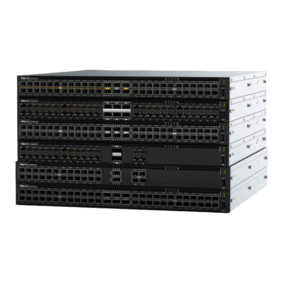
- Page 1 Dell Networking S4100-ON Series Set-Up Guide July 2017...
- Page 2 Notes, cautions, and warnings NOTE: A NOTE indicates important information that helps you make better use of your product. CAUTION: A CAUTION indicates either potential damage to hardware or loss of data and tells you how to avoid the problem. WARNING: A WARNING indicates a potential for property damage, personal injury, or death.
-
Page 3: Table Of Contents
ReadyRails installation..............................10 1U Tool-less mount installation............................11 Two-post flush-mount installation..........................12 Two-post center-mount installation..........................13 Four-post threaded installation............................14 S4100-ON Series system installation..........................15 1U front-rack installation..............................15 Optics installation................................17 Optics removal.................................. 18 System power-up................................18 Power up sequence..............................18 After system installation..............................18... -
Page 4: About This Guide
• Information symbols Related documents For more information about the S4100–ON Series, see the following documents: • Dell Networking OS10 Enterprise Edition Release Notes • Dell Networking OS10 Enterprise Edition User Guide • Dell Networking S4100–ON Series Setup Guide •... - Page 5 WARNING: The Warning icon signals information about hardware handling that could result in injury. WARNING: The ESD Warning icon requires that you take electrostatic precautions when handling the device. About this guide...
-
Page 6: Site Preparations
Site preparations The S4100–ON Series is suitable for installation as part of a common bond network (CBN). You can install the system in: • Network telecommunication facilities • Data centers • Other locations where the National Electric Code (NEC) applies For more information about the S4100–ON Series specifications, see Specifications. -
Page 7: Rack Mounting
Be sure to order the fans suitable to support your site’s ventilation. Use a single type of airflow fan in your system. Do not mix reverse and normal airflows in a single S4100-ON Series switch. For proper ventilation, position the S4100–ON Series switch in an equipment rack or cabinet with a minimum of 5 inches (12.7 cm) of clearance around the exhaust vents. -
Page 8: Storing Components
Storing components If you do not install your S4100–ON Series swtich and components immediately, Dell recommends properly storing the switch and all optional components following these guidelines: • Storage location temperature must remain constant. The storage range is from -40° to 149°F (-40° to 65°C). •... -
Page 9: S4100-On Series Installation
Two sets of rail kits, no tools required • Two PSUs • Three or four fan units • Two country- and region-specific AC power cords • Dell Networking S4100–ON Series Setup Guide • Safety and Regulatory Information • Warranty and Support Information S4100–ON Series installation... -
Page 10: Unpack
Unpack Place the container on a clean, flat surface and cut all straps securing the container. Open the container or remove the container top. Carefully remove the switch from the container and place it on a secure and clean surface. Remove all packing material. -
Page 11: 1U Tool-Less Mount Installation
Figure 2. Separate rails 1U Tool-less mount installation NOTE: For more installation instructions, see the installation labels attached to the rail assembly. Face the ReadyRails flange ears facing outward. Place one rail between the left and right vertical posts. Align and seat the back flange rail pegs in the back vertical post flange. -
Page 12: Two-Post Flush-Mount Installation
Figure 3. 1U tool-less installation Align and seat the front flange pegs in the holes on the front side of the vertical post. NOTE: Be sure that the rails click into place and are secure. Repeat this procedure for the second rail. To remove each rail, pull on the latch release button on each flange ear and unseat each rail. -
Page 13: Two-Post Center-Mount Installation
Figure 4. Two-post flush-mount installation Attach one rail to the front post flange with two user-supplied screws, item 2. Slide the plunger bracket forward against the vertical post and secure the plunger bracket to the post flange with two user-supplied screws, see item 3. -
Page 14: Four-Post Threaded Installation
Figure 5. Two-post center-mount installation Slide the back bracket towards the post. Secure it to the post flange with two user-supplied screws, items 2 and 3. Repeat this procedure for the second rail. Four-post threaded installation NOTE: For more installation instructions, see the installation labels attached to the rail assembly. Remove the latch castings from each end of the ReadyRails assemblies. -
Page 15: S4100-On Series System Installation
For each rail, attach the front and back flanges to the post flanges with two user-supplied screws at each end. S4100-ON Series system installation You can mount the system in the 1U front-rack two-post, flush, or center configuration or a four-post configuration. The following is an example of a front-rack configuration: For the 1U two-post configurations, slide the system into the rails in the same manner as the four-post configurations. - Page 16 Figure 7. Switch rail attachment After you install both rails, line them up on the ReadyRails. Slide the switch in until it is flush with the front of rack. About three inches before you fully insert your system, the rail locking feature engages to keep the switch from inadvertently sliding out and falling.
-
Page 17: Optics Installation
Figure 8. Front rack installation NOTE: Do not the use the mounted Ready-Rails as a shelf or a workplace. Tighten the two thumb screws and rack screws. To remove the chassis from the rack or cabinet, press in the two side-release bars on the chassis at the same time and slide the chassis forward. -
Page 18: Optics Removal
Optics removal Remove an optic by pushing the tab on the optic and sliding the optic from the port. When removing optics with direct attach cables (DACs) from the port, pull the release tab firmly and steadily. Before pulling the release tab, you may need to gently push the optic into the port to ensure that it is seated properly. -
Page 19: Specifications
Specifications This section lists the S4100–ON Series system specifications. CAUTION: Operate the product at an ambient temperature not higher than 113°F—45°C. CAUTION: Lithium Battery Caution: There is a danger of explosion if the battery is incorrectly replaced. Replace only with same or equivalent type of battery. - Page 20 Parameter Specifications Maximum thermal output 600 W = 2047 BTU/Hr Maximum operational altitude 10,000 feet (3,048 meters) Maximum non-operational altitude 39,370 feet (12,000 meters) Shock SV0115 — ODM Table 3. AC power requirements Parameter Specifications Power supply 100–240 VAC 50/60 Hz Maximum current draw per system 6A/5A at 100/120V AC 3A/2.5A at 200/240V AC Maximum power consumption...
-
Page 21: Dell Support
The Dell Networking support site provides integrated, secure access to these services. To access the Dell Networking Support site, go to www.dell.com/support/. To display information in your language, scroll down to the bottom of the web page and select your country from the drop-down menu.
Need help?
Do you have a question about the S4100-ON Series and is the answer not in the manual?
Questions and answers