Gigabyte GA-8IPE1000 User Manual
Ga-8ipe1000 series intel pentium 4 processor motherboard
Hide thumbs
Also See for GA-8IPE1000:
- User manual (120 pages) ,
- User manual (112 pages) ,
- User manual (112 pages)

Related Manuals for Gigabyte GA-8IPE1000


Summary of Contents for Gigabyte GA-8IPE1000
- Page 1 GA-8IPE1000 Series Intel Pentium 4 Processor Motherboard ® ® User's Manual Rev. 4002 12ME-8IPE1K4-4002...
- Page 3 Gigabyte's prior written permission. Specifications and features are subject to change without prior notice. Product Manual Classification In order to assist in the use of this product, Gigabyte has categorized the user manual in the following: For quick installation, please refer to the "Hardware Installation Guide" included with the product.
-
Page 4: Table Of Contents
Table of Contents GA-8IPE1000 Series Motherboard Layout ... 6 Block Diagram ... 7 Chapter 1 Hardware Installation ... 9 Considerations Prior to Installation ... 9 Feature Summary ... 10 Installation of the CPU and Heatsink ... 12 1-3-1 Installation of the CPU ... 12 1-3-2 Installation of the Heatsink ... - Page 5 Chapter 3 Drivers Installation ... 49 Install Chipset Drivers ... 49 Software Application ... 50 Software Information ... 50 Hardware Information ... 51 Contact Us ... 51 Chapter 4 Appendix ... 53 Unique Software Utilities ... 53 4-1-1 Xpress Recovery Introduction ... 53 4-1-2 Flash BIOS Method Introduction ...
-
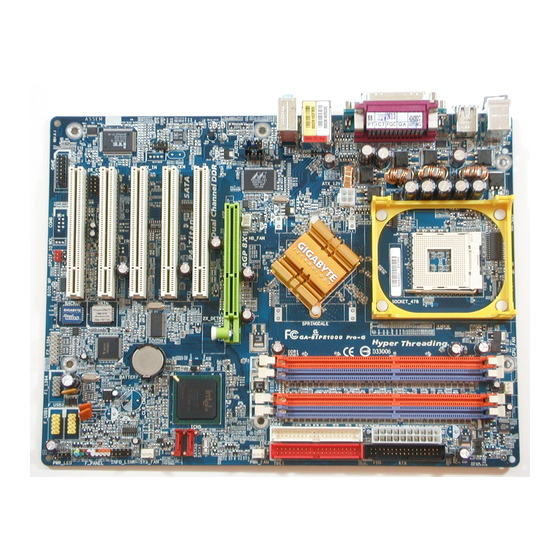
Page 6: Ga-8Ipe1000 Series Motherboard Layout
GA-8IPE1000 Series Motherboard Layout KB_MS ATX_12V CD_IN RTL8110S or RTL8100C F_AUDIO CODEC SUR_CEN GAME SPDIF_IO Only for GA-8IPE1000-G. Only for GA-8IPE1000-L. CPU_FAN Socket 478 Intel 865PE PCI1 PCI2 PCI3 BIOS SATA0 PCI4 PCI5 F_USB2 F_USB1 INFO_LINK PWR_LED - 6 -... -
Page 7: Block Diagram
Block Diagram AGP 4X/8X AGPCLK 66MHz RJ45 5 PCI RTL8110S RTL8100C PCI Bus 33MHz CODEC PCICLK (33MHz) Only for GA-8IPE1000-G. Only for GA-8IPE1000-L. Pentium 4 Socket 478 System Bus 400/533/800 MHz Intel 865PE RJ45 Intel ICH5 2 Serial 8 USB... - Page 8 - 8 -...
-
Page 9: Chapter 1 Hardware Installation
2. Damage as a result of violating the conditions recommended in the user manual. 3. Damage due to improper installation. 4. Damage due to use of uncertified components. 5. Damage due to use exceeding the permitted parameters. 6. Product determined to be an unofficial Gigabyte product. - 9 - Hardware Installation... -
Page 10: Feature Summary
Feature Summary Motherboard GA-8IPE1000-G or GA-8IPE1000-L or GA-8IPE1000 Socket 478 for Intel Supports 800/533/400MHz FSB L2 cache varies with CPU Chipset Northbridge: Intel Southbridge: Intel Memory 4 DDR DIMM memory slots (supports up to 4GB memory) Supports dual channel DDR 400/333/266 DIMM Supports 2.5V DDR DIMM... - Page 11 I/O Control SMSC LPC47M997-NR Hardware Monitor System voltage detection CPU temperature detection CPU / System fan speed detection BIOS Use of licensed AWARD BIOS Supports Q-Flash Additional Features Supports @BIOS Supports EasyTune 5 Overclocking Over voltage via BIOS (CPU/ AGP/ DDR) Over clock via BIOS (CPU/ AGP/ DDR/ PCI) Form Factor ATX form factor;...
-
Page 12: Installation Of The Cpu And Heatsink
CPU and gently press the metal lever back into its original position. Please use extra care when installing the CPU. The CPU will not fit if positioned incorrectly. Rather than applying force, please change the positioning of the CPU. GA-8IPE1000 Series Motherboard - 12 -... -
Page 13: Installation Of The Heatsink
1-3-2 Installation of the Heatsink Fig.1 Before installing the heat sink, please first add an even layer of heat sink paste on the surface of the CPU. Install all the heat sink components (Please refer to the heat sink manual for detailed installation instructions). Fig.2 Please connect the heat sink power connector to the CPU_FAN connector located on the motherboard so that the heat sink can properly function to... -
Page 14: Installation Of Memory
DIMM socket. Then push it down. Fig.2 Close the plastic clip at both edges of the DIMM sockets to lock the DIMM module. Reverse the installation steps when you wish to remove the DIMM module. GA-8IPE1000 Series Motherboard Notch - 14 -... - Page 15 GA-8IPE1000 Series supports the Dual Channel Technology. After operating the Dual Channel Technology, the bandwidth of Memory Bus will add double up to 6.4GB/s(DDR400) or 5.3GB/s(DDR333). GA-8IPE1000 Series includes 4 DIMM sockets, and each Channel has two DIMM sockets as following: Channel A : DDR 1, DDR 2...
-
Page 16: Installation Of Expansion Cards
Power on the computer, if necessary, setup BIOS utility of expansion card from BIOS. Install related driver from the operating system. Installing a AGP VGA card: GA-8IPE1000 Series Motherboard Please carefully pull out the small white- drawable bar at the end of the AGP slot when you try to install/uninstall the VGA card. -
Page 17: I/O Back Panel Introduction
Connect the stereo speakers or earphone to this connector. MIC In Microphone can be connected to MIC In jack. You can use audio software to configure 2-/4-/6-/8-channel audio functioning. Only for GA-8IPE1000-G. Only for GA-8IPE1000-L. - 17 - Hardware Installation... -
Page 18: Connectors Introduction
3) CPU_FAN 4) SYS_FAN 5) FDD 6) IDE1 / IDE2 7) SATA0 / SATA1 8) PWR_LED 9) BATTERY 10) F_PANEL GA-8IPE1000 Series Motherboard 6 15 11) F_AUDIO 12) CD_IN 13) SUR_CEN 14) SPDIF_IO 15) F_USB1 / F_USB2 16) IR 17) GAME... - Page 19 1/2) ATX_12V/ATX (Power Connector) With the use of the power connector, the power supply can supply enough stable power to all the components on the motherboard. Before connecting the power connector, please make sure that all components and devices are properly installed. Align the power connector with its proper location on the motherboard and connect tightly.
- Page 20 The FDD connector is used to connect the FDD cable while the other end of the cable connects to the FDD drive. The types of FDD drives supported are: 360KB, 720KB, 1.2MB, 1.44MB and 2.88MB. Please connect the red power connector wire to the pin1 position. GA-8IPE1000 Series Motherboard Pin No. Definition...
- Page 21 6) IDE1 / IDE2 (IDE Connector) An IDE device connects to the computer via an IDE connector. One IDE connector can connect to one IDE cable, and the single IDE cable can then connect to two IDE devices (hard drive or optical drive). If you wish to connect two IDE devices, please set the jumper on one IDE device as Master and the other as Slave (for information on settings, please refer to the instructions located on the IDE device).
- Page 22 8) PWR_LED PWR_LED is connect with the system power indicator to indicate whether the system is on/off. It will blink when the system enters suspend mode. 9) BATTERY GA-8IPE1000 Series Motherboard Pin No. Definition MPD+ MPD- MPD- Danger of explosion if battery is incorrectly replaced.
-
Page 23: F_Panel (Front Panel Jumper)
10) F_PANEL (Front Panel Jumper) Please connect the power LED, PC peaker, reset switch and power switch etc. of your chassis front panel to the F_PANEL connector according to the pin assignment below. MSG (Message LED/Power/Sleep LED) (Yellow) PW (Power Switch) (Red) SPEAK (Speaker Connector) (Amber) - Page 24 12) CD_IN (CD In Connector) Connect CD-ROM or DVD-ROM audio out to the connector. GA-8IPE1000 Series Motherboard Pin No. Definition MIC_BIAS...
- Page 25 13) SUR_CEN (Surround Center Connector) Please contact your nearest dealer for optional SUR_CEN cable. 14) SPDIF_IO (SPDIF In / Out Connector) The SPDIF output is capable of providing digital audio to external speakers or compressed AC3 data to an external Dolby Digital Decoder. Use this feature only when your stereo system has digital input function.
- Page 26 For optional front USB cable, please contact your local dealer. 16) IR Be careful with the polarity of the IR connector while you connect the IR. Please contact your nearest dealer for optional IR device. GA-8IPE1000 Series Motherboard Pin No. Definition Power...
- Page 27 17) GAME (GAME Connector) This connector supports joystick, MIDI keyboard and other relate audio devices. 18) INFO_LINK This connector allows you to connect some external devices to provide you extra function. Pin No. Pin No. - 27 - Definition GRX1_R GPSA2 GPX2_R GPY2_R...
- Page 28 You may clear the CMOS data to its default values by this jumper. To clear CMOS, temporarily short 1-2 pin. Default doesn't include the "Shunter" to prevent from improper use this jumper. GA-8IPE1000 Series Motherboard Open: Normal Short: Clear CMOS...
-
Page 29: Chapter 2 Bios Setup
BIOS needs to be reset to its original settings. If you wish to upgrade to a new BIOS, either GIGABYTE's Q-Flash or @BIOS utility can be used. Q-Flash allows the user to quickly and easily update or backup BIOS without entering the operating system. -
Page 30: The Main Menu (For Example: Bios Ver. : E8)
This setup page is control CPU clock and frequency ratio. Load Fail-Safe Defaults Fail-Safe Defaults indicates the value of the system parameters which the system would be in safe configuration. GA-8IPE1000 Series Motherboard Load Fail-Safe Defaults Load Optimized Defaults Set Supervisor Password Set User Password Save &... - Page 31 Load Optimized Defaults Optimized Defaults indicates the value of the system parameters which the system would be in best performance configuration. Set Supervisor Password Change, set, or disable password. It allows you to limit access to the system and Setup, or just to Setup. Set User Password Change, set, or disable password.
-
Page 32: Standard Cmos Features
Number of heads Precomp Write precomp Landing Zone Landing zone Sector Number of sectors If a hard disk has not been installed, select NONE and press <Enter>. GA-8IPE1000 Series Motherboard Standard CMOS Features Tue, Oct 26 2004 22:31:24 [None] [None] [None] [None] [1.44M, 3.5"]... -
Page 33: Extended Memory
Drive A / Drive B The category identifies the types of floppy disk drive A or drive B that has been installed in the computer. None No floppy drive installed 360K, 5.25" 5.25 inch PC-type standard drive; 360K byte capacity. 1.2M, 5.25"... -
Page 34: Advanced Bios Features
CPU Hyper-Threading Enabled Enables CPU Hyper Threading Feature. This feature is only working for operating system with multi-processors mode supported. (Default value) Disabled Disables CPU Hyper Threading. GA-8IPE1000 Series Motherboard Advanced BIOS Features [Press Enter] [Floppy] [Hard Disk] [CDROM] [Setup]... -
Page 35: Integrated Peripherals
Disabled Disable onboard 1st channel IDE port. On-Chip Secondary PCI IDE Enabled Enable onboard 2nd channel IDE port. (Default value) Disabled Disable onboard 2nd channel IDE port. Only for GA-8IPE1000-G. Only for GA-8IPE1000-L. Integrated Peripherals [Enabled] [Enabled] [Auto] SATA Port0... - Page 36 Auto Auto detect AC97 audio function. (Default value) Disabled Disable AC97 audio function. Onboard H/W LAN Enabled Enable onboard H/W LAN function. (Default value) Disabled Disable this function. Only for GA-8IPE1000-G. Only for GA-8IPE1000-L. GA-8IPE1000 Series Motherboard - 36 -...
- Page 37 This function will available when "UART Mode Select" doesn't set at Normal. RxD2, TxD2 Set IR pins to use RxD2, TxD2. IR-Rx2Tx2 Set IR pins to use IR-Rx2Tx2. (Default value) Only for GA-8IPE1000-G. Only for GA-8IPE1000-L. - 37 - BIOS Setup...
- Page 38 Set Midi Port Address to 300. Set Midi Port Address to 290. Disabled Disable this function. (Default value) Midi Port IRQ Set Midi Port IRQ to 5. Set Midi Port IRQ to 10. (Default value) GA-8IPE1000 Series Motherboard - 38 -...
-
Page 39: Power Management Setup
Power Management Setup CMOS Setup Utility-Copyright (C) 1984-2004 Award Software ACPI Suspend Type Power LED in S1 state Off by Power button AC BACK Function PME Event Wake Up ModemRingOn Resume by Alarm x Date (of Month) Alarm x Time (hh:mm:ss) Alarm POWER ON Function : Move Enter: Select... - Page 40 Press any key to power on the system. Mouse Double click on mouse left button to power on the system. Mouse/Any KEY Press any key or double click on mouse left button to power on the system. GA-8IPE1000 Series Motherboard - 40 -...
-
Page 41: Pnp/Pci Configurations
PnP/PCI Configurations CMOS Setup Utility-Copyright (C) 1984-2004 Award Software PCI 1/5 IRQ Assignment PCI 2 IRQ Assignment PCI 3 IRQ Assignment PCI 4 IRQ Assignment : Move Enter: Select F5: Previous Values PCI 1/5 IRQ Assignment Auto 3,4,5,7,9,10,11,12,14,15 PCI 2 IRQ Assignment Auto 3,4,5,7,9,10,11,12,14,15 PCI 3 IRQ Assignment... -
Page 42: Pc Health Status
Current CPU Temperature Detect CPU temperature automatically. Current Voltage(V) Vcore / DDR25V / +3.3V / +12V Detect system's voltage status automatically. Current CPU/SYSTEM FAN Speed (RPM) Detect CPU/SYSTEM fan speed status automatically. GA-8IPE1000 Series Motherboard PC Health Status 1.35V 2.39V 3.28V 12.09V... -
Page 43: Frequency/Voltage Control
Frequency/Voltage Control CMOS Setup Utility-Copyright (C) 1984-2004 Award Software CPU Clock Ratio CPU Host Clock Control x CPU Host Frequency (Mhz) x AGP/PCI/SRC Fixed Memory Frequency For Memory Frequency (Mhz) AGP/PCI/SRC Frequency (Mhz) DIMM OverVoltage Control AGP OverVoltage Control CPU OverVoltage Control : Move Enter: Select F5: Previous Values... - Page 44 Set AGP OverVoltage Control to +0.3V. CPU OverVoltage Control Normal Set CPU OverVoltage Control to Normal. (Default value) +5.0% Set CPU OverVoltage Control to +5.0%. +7.5% Set CPU OverVoltage Control to +7.5%. +10.0% Set CPU OverVoltage Control to +10.0%. GA-8IPE1000 Series Motherboard - 44 -...
-
Page 45: Load Fail-Safe Defaults
Load Fail-Safe Defaults CMOS Setup Utility-Copyright (C) 1984-2004 Award Software Standard CMOS Features Advanced BIOS Features Integrated Peripherals Power Management Setup PnP/PCI Configurations PC Health Status Frequency/Voltage Control ESC: Quit F8: Q-Flash Fail-Safe defaults contain the most appropriate values of the system parameters that allow minimum system performance. -
Page 46: Set Supervisor/User Password
Setup Menu. If you select "Setup" at "Password Check" in Advance BIOS Features Menu, you will be prompted only when you try to enter Setup. GA-8IPE1000 Series Motherboard Load Fail-Safe Defaults Load Optimized Defaults... -
Page 47: Save & Exit Setup
2-11 Save & Exit Setup CMOS Setup Utility-Copyright (C) 1984-2004 Award Software Standard CMOS Features Advanced BIOS Features Integrated Peripherals Power Management Setup PnP/PCI Configurations PC Health Status Frequency/Voltage Control ESC: Quit F8: Q-Flash Type "Y" will quit the Setup Utility and save the user setup value to RTC CMOS. Type "N"... - Page 48 GA-8IPE1000 Series Motherboard - 48 -...
-
Page 49: Chapter 3 Drivers Installation
Pack. After install Windows Service Pack, it will show a question mark "?" in "Universal Serial Bus controller" under "Device Manager". Please remove the question mark and restart the system (System will auto-detect the right USB2.0 driver). Only for GA-8IPE1000-G. Only for GA-8IPE1000-L. (12) -
Page 50: Software Application
Software Application This page displays all the tools that Gigabyte developed and some free software, you can choose anyone you want and press "install" to install them. Software Information This page lists the contents of software and drivers in this CD-title. -
Page 51: Hardware Information
Hardware Information This page lists all device you have for this motherboard. Contact Us Please see the last page for details. - 51 - Drivers Installation... - Page 52 GA-8IPE1000 Series Motherboard - 52 -...
-
Page 53: Chapter 4 Appendix
Once you have completed this step, subsequent access to Xpress Recovery can also function by pressing the F9 key during computer power on. Verifying DMI Pool Data Boot from CD: Xpress Recovery V1.0 (C) Copy Right 2003. GIGABYTE Technology CO. , Ltd. 1. Execute Backup Utility 2. Execute Restore Utility 3. Remove Backup Image 4. - Page 54 Press DEL to enter SETUP / Q-Flash, F9 For Xpress Recovery 08/16/2002-I845GE-6A69YG01C-00 Xpress Recovery V1.0 (C) Copy Right 2003. GIGABYTE Technology CO. , Ltd. If you have already entered Xpress Recovery by booting from the CD-ROM, you can enter Xpress Recovery in the future by pressing the F9 key.
- Page 55 1. Execute Backup Utility: Press B to Backup your System or Esc to Exit The backup utility will automatically scan your system and back up data as a backup image in your hard drive. Not all systems support access to Xpress Recovery by pressing the F9 key during computer power on.
-
Page 56: Flash Bios Method Introduction
Updating BIOS with Q-Flash Utility on Dual BIOS Motherboards. Some of Gigabyte motherboards are equipped with dual BIOS. In the BIOS menu of the motherboards supporting Q-Flash and Dual BIOS, the Q-Flash utility and Dual BIOS utility are combined in the same screen. - Page 57 Entering the Q-Flash utility: Step1: To use Q-Flash utility, you must press Del in the boot screen to enter BIOS menu. CMOS Setup Utility-Copyright (C) 1984-2004 Award Software Standard CMOS Features Advanced BIOS Features Integrated Peripherals Power Management Setup PnP/PCI Configurations PC Health Status MB Intelligent Tweaker(M.I.T.) ESC: Quit...
- Page 58 Copy Main ROM Data to Backup Don't Turn Off Power or Reset System Enter : Run After BIOS file is read, you'll see a confirmation dialog box asking you "Are you sure to update BIOS?" GA-8IPE1000 Series Motherboard Dual BIOS Utility Disable 1 file(s) found...
- Page 59 3. Press Y button on your keyboard after you are sure to update BIOS. Then it will begin to update BIOS. The progress of updating BIOS will be displayed. Please do not take out the floppy disk when it begins flashing BIOS. 4.
-
Page 60: Updating Bios With Q-Flash Utility On Single-Bios Motherboards
Press Y on your keyboard to save and exit. Part Two: Updating BIOS with Q-Flash Utility on Single-BIOS Motherboards. This part guides users of single-BIOS motherboards how to update BIOS using the Q-Flash CMOS Setup Utility-Copyright (C) 1984-2004 Award Software Standard CMOS Features Advanced BIOS Features... - Page 61 Exploring the Q-Flash utility screen The Q-FlashBIOS utility screen consists of the following key components. Flash Type/Size...SST 49LF003A Task menu for Q-Flash utility Enter : Run Task menu for Q-Flash utility: Contains the names of three tasks. Blocking a task and pressing Enter key on your keyboard to enable execution of the task.
- Page 62 Press Del to enter BIOS menu after system reboots and "Load BIOS Fail-Safe Defaults". See how to Load BIOS Fail-Safe Defaults, please kindly refer to Step 6 to 7 in Part One. Congratulation!! You have updated BIOS successfully!! GA-8IPE1000 Series Motherboard Q-Flash Utility V1.30 Keep DMI Data...
- Page 63 Please search for BIOS unzip file, downloading from internet or any other methods (such as: 8IPEKG4.E8). Complete update process following the instruction. Utility Fig 2. Installation complete and run @BIOS Click Sart/ Programs/ GIGABYTE/@BIOS Fig 4. Select the desired @BIOS server - 63 - Appendix...
- Page 64 III. In method I, if the BIOS file you need cannot be found in @BIOS website for downloading and updating it according to method II. IV. Please note that any interruption during updating will cause system unbooted. GA-8IPE1000 Series Motherboard server, please go onto Gigabyte's - 64 -...
-
Page 65: 4- / 6- / 8- Channel Audio Function Introduction
4-1-3 2- / 4- / 6- / 8- Channel Audio Function Introduction The installation of audio software for Windows 98/ 2000/ ME/ XP is very simple. Please follow the steps to install the function. (Following pictures are in Windows XP) Stereo Speakers Connection and Settings: We recommend that you use the speaker with amplifier to acquire the best sound effect if the stereo output is applied. - Page 66 Click "Speaker Configuration" and select the "UAJ Function". Then click on the left selection bar and select "4CH Speaker" to complete 4 channel audio configuration. GA-8IPE1000 Series Motherboard Line In (Rear Speaker Out) Line Out (Front Speaker Out) - 66 -...
- Page 67 6 Channel Audio Setup STEP 1: Connect the Front Speakers to "Line Out", the Rear Speakers to "Line In", and the Center/Subwoofer Speakers to "MIC In". STEP 2: Following installation of the audio driver, you find a Sound Effect icon on the lower right hand taskbar. Click the icon to select the function.
- Page 68 Surround-Kit "REAR R/L" port. Connect the center/subwoofer channels to the Surround-Kit "SUB CENTER" and the R/L channels to the Surround-Kit "SUR BACK" port. GA-8IPE1000 Series Motherboard - 68 -...
- Page 69 Method 2: Connect the front channels to the "Line Out" port located on the audio panel and the rear channels to the "Line In" port. Connect the center/subwoofer channels to the "MIC In" port located on the audio panel and the R/L channels to the Surround-Kit "SUR BACK"...
- Page 70 Fiber connecting port. Connect the SPDIF output device to the rear bracket of PC, and fix it with screw. Connect SPDIF device to the motherboard. Connect SPDIF to the SPDIF decoder. GA-8IPE1000 Series Motherboard - 70 -...
- Page 71 Jack-Sensing and UAJ Introduction Jack-Sensing provides audio connectors error-detection function. Install Microsoft DirectX8.1 or later version before to enable Jack-Sensing support for Windows 98/ 98SE/ 2000/ ME. Jack-Sensing includes 2 parts: AUTO and MANUAL. Following is an example for 2 channels (Following pictures are in Windows XP): Introduction of audio connectors You may connect CDROM, Walkman or others audio...
-
Page 72: Uaj Introduction
(Line-in/ Line-out). That means users do not need to worry the audio device should be plug in Line-in or Line-out jack, the device will work perfectly after UAJ is activated. Enable UAJ function: You can click "UAJ Automatic" button to enable UAJ function. GA-8IPE1000 Series Motherboard - 72 -... -
Page 73: Troubleshooting
Question 8: How do I disable onboard VGA card in order to add an external VGA card? Answer: Gigabyte motherboards will auto-detect the external VGA card after it is plugged in, so you don't need to change any setting manually to disable the onboard VGA. - Page 74 1. Advanced BIOS features-->(SATA)/RAID/SCSI boot order: "SCSI" 2. Advanced BIOS features--> First boot device: "SCSI" Then it depends on the mode(RAID or ATA) that you need to set in RAID/ SCSI BIOS. GA-8IPE1000 Series Motherboard AWARD BIOS Beep Codes 1 short: System boots successfully...
- Page 75 - 75 - Appendix...
- Page 76 GA-8IPE1000 Series Motherboard - 76 -...
- Page 77 - 77 - Appendix...
- Page 78 GA-8IPE1000 Series Motherboard - 78 -...
- Page 79 TEL: +886 (2) 8912-4888 FAX: +886 (2) 8912-4003 Tech. Support : http://tw.giga-byte.com/TechSupport/ServiceCenter.htm Non-Tech. Support(Sales/Marketing) : http://ggts.gigabyte.com.tw/nontech.asp WEB address (English): http://www.gigabyte.com.tw WEB address (Chinese): http://chinese.giga-byte.com U.S.A. G.B.T. INC. Address: 17358 Railroad St, City of Industry, CA 91748. TEL: +1 (626) 854-9338 FAX: +1 (626) 854-9339 Tech.
- Page 80 China NINGBO G.B.T. TECH. TRADING CO., LTD. Tech. Support : http://cn.giga-byte.com/TechSupport/ServiceCenter.htm Non-Tech. Support(Sales/Marketing) : http://ggts.gigabyte.com.tw/nontech.asp WEB address : http://www.gigabyte.com.cn Shanghai TEL: +86-021-63410999 FAX: +86-021-63410100 Beijing TEL: +86-010-82886651 FAX: +86-010-82888013 Wuhan TEL: +86-027-87851061 FAX: +86-027-87851330 GuangZhou TEL: +86-020-87586074 FAX: +86-020-85517843 Chengdu...
Need help?
Do you have a question about the GA-8IPE1000 and is the answer not in the manual?
Questions and answers