Gigabyte GA-8IPE1000 User Manual
Ga-8ipe1000 series p4 titan series motherboard
Hide thumbs
Also See for GA-8IPE1000:
- User manual (120 pages) ,
- User manual (112 pages) ,
- User manual (80 pages)
Table of Contents
Advertisement
When you installing AGP card, please make sure the following
notice is fully understood and practiced. If your AGP card has
"AGP 4X/8X (1.5V) notch"(show below), please make sure your
AGP card is AGP 4X/8X (1.5V).
Caution: AGP 2X card is not supported by Intel
G) / 850(E) / E7205 / 865(G/PE/P) / 875P. You might experience system
unable to boot up normally. Please insert an AGP 4X/8X card.
Example 1: Diamond Vipper V770 golden finger is compatible with 2X/4X
mode AGP slot. It can be switched between AGP 2X(3.3V) or 4X(1.5V)
mode by adjusting the jumper. The factory default for this card is
2X(3.3V). The GA-8IPE1000 Series (or any AGP 4X/8X only)
motherboards might not function properly, if you install this card without
switching the jumper to 4X(1.5V) mode in it.
Example 2: Some ATi Rage 128 Pro graphics cards made by "Power Color",
the graphics card manufacturer & some SiS 305 cards, their golden finger
is compatible with 2X(3.3V)/4X(1.5V) mode AGP slot, but they support 2X
(3.3V) only. The GA-8IPE1000 Series (or any AGP 4X/8X only)
motherboards might not function properly, If you install this card in it.
Note : Although Gigabyte's AG32S(G) graphics card is based on ATi Rage
128 Pro chip, the design of AG32S(G) is compliance with AGP 4X(1.5V)
specification. Therefore, AG32S(G) will work fine with Intel
845(E/G) / 850(E) / E7205 / 865(G/PE/P) / 875P based motherboards.
Before you install PCI cards, please remove the Dual BIOS label from
PCI slots if there is one.
AGP 4X/8X notch
845(GE/PE) / 845(E/
®
845(GE/PE) /
®
Advertisement
Table of Contents

Related Manuals for Gigabyte GA-8IPE1000


Summary of Contents for Gigabyte GA-8IPE1000
- Page 1 (3.3V) only. The GA-8IPE1000 Series (or any AGP 4X/8X only) motherboards might not function properly, If you install this card in it. Note : Although Gigabyte's AG32S(G) graphics card is based on ATi Rage 128 Pro chip, the design of AG32S(G) is compliance with AGP 4X(1.5V) specification.
- Page 2 M The author assumes no responsibility for any errors or omissions that may appear in this document nor does the author make a commitment to update the information contained herein. M Third-party brands and names are the property of their respective owners. M Please do not remove any labels on motherboard, this may void the warranty of this motherboard.
-
Page 3: Declaration Of Conformity
Ausschlager Weg 41, 1F, 20537 Hamburg, Germany ( description of the apparatus, system, installation to which it refers) GA-8IPE1000 Pro/GA-8IPE1000/GA-8IPE1000-L/GA-8IPE1000 Pro2 (reference to the specification under which conformity is declared) o EN 55011 Limits and methods of measurement of radio disturbance characteristics of... - Page 4 (2) this device must accept any inference received, including that may cause undesired operation. Representative Person’s Name: G.B.T. INC. (U.S.A.) Address: 17358 Railroad Street City of Industry, CA 91748 (818) 854-9338/ (818) 854-9339 Motherboard GA-8IPE1000 Pro/GA-8IPE1000/ GA-8IPE1000-L/GA-8IPE1000 Pro2 ERIC LU Signature: Eric Lu Date: July 22, 2003...
- Page 5 GA-8IPE1000 Series P4 Titan Series Motherboard USER'S MANUAL Pentium 4 Processor Motherboard ® Rev. 2001 12ME-8IPEKP2W-2001...
-
Page 6: Table Of Contents
Table of Content Warning ...4 Chapter 1 Introduction ...5 Features Summary ... 5 GA-8IPE1000 Series Motherboard Layout ... 8 Block Diagram ... 9 Chapter 2 Hardware Installation Process ... 11 Step 1: Install the Central Processing Unit (CPU) ... 12 Step 1-1: CPU Installation ... - Page 7 2-/4-/6-Channel Audio Function Introuction... 78 Jack-Sensing Introuction ... 84 UAJ Introuction ... 86 Xpress Recovery Introduction ... 88 Chapter 5 Appendix ... 91 (*) For GA-8IPE1000 Pro only. ) For GA-8IPE1000 Pro2 only..67 - 3 - Table of Content...
-
Page 8: Warning
Warning Computer motherboards and expansion cards contain very delicate Integrated Circuit (IC) chips. To protect them against damage from static electricity, you should follow some precautions whenever you work on your computer. Unplug your computer when working on the inside. -
Page 9: Chapter 1 Introduction
Chapter 1 Introduction Features Summary Form Factor — 30.5cm x 23.0cm ATX size form factor, 4 layers PCB. Motherboard — GA-8IPE1000 Series Motherboard: — Socket 478 for Intel — Support Intel — Support Intel — Intel Pentium — 2nd cache depends on CPU Chipset —... - Page 10 — PS/2 Keyboard interface and PS/2 Mouse interface BIOS — Licensed AWARD BIOS — Supports Dual BIOS — Supports Multi Language — Supports Face Wizard (*) For GA-8IPE1000 Pro only. ) For GA-8IPE1000 Pro2 only. ) For GA-8IPE1000-L only. GA-8IPE1000 Series Motherboard and 2.88M bytes. IEEE1394 (bycable)
- Page 11 Whether your system can run under these specific bus frequencies properly will depend on your hardware configurations, including CPU, Chipsets, SDRAM, Cards… .etc. (*) For GA-8IPE1000 Pro only. ) For GA-8IPE1000 Pro2 only. - 7 -...
-
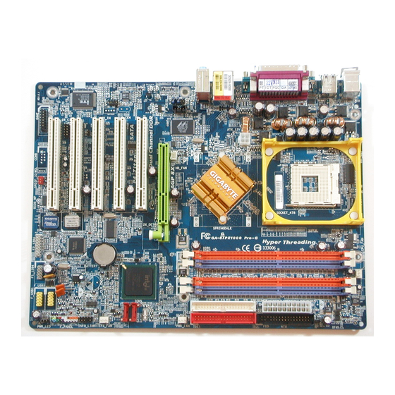
Page 12: Ga-8Ipe1000 Series Motherboard Layout
CODEC AUX_IN IR_CIR GAME SPDIF_IO (*) For GA-8IPE1000 Pro only. ) For GA-8IPE1000 Pro2 only. ) For GA-8IPE1000-L only. Note: If the NorthBridge on the motherboard has a fan sink, then the motherboard contains a NB_FAN connector. GA-8IPE1000 Series Motherboard... -
Page 13: Block Diagram
AC97 PCICLK CODEC (33MHz) PCICLK (33MHz) USBCLK (48MHz) 14.318 MHz 33 MHz 24 MHz (*) For GA-8IPE1000 Pro only. ) For GA-8IPE1000 Pro2 only. ) For GA-8IPE1000-L only. Pentium 4 CPUCLK+/- (100/133/200MHz) Socket 478 System Bus 400/533/800MHz 266/333/400MHz Intel 865PE... - Page 14 GA-8IPE1000 Series Motherboard - 10 -...
-
Page 15: Chapter 2 Hardware Installation Process
Chapter 2 Hardware Installation Process To set up your computer, you must complete the following steps: Step 1- Install the Central Processing Unit (CPU) Step 2- Install memory modules Step 3- Install expansion cards Step 4- Connect ribbon cables, cabinet wires, and power supply Step 4 Step 4 Step 3... -
Page 16: Step 1: Install The Central Processing Unit (Cpu)
1. Angling the rod to 65-degree maybe feel a kind of tight, and then continue pull the rod to 90-degree when a noise "cough" made. Pin1 indicator 3. CPU Top View GA-8IPE1000 Series Motherboard Socket Actuation Lever 2. Pull the rod to the 90-degree directly. -
Page 17: Step 1-2 : Cpu Cooling Fan Installation
Step 1-2 : CPU Cooling Fan Installation Before installing the CPU Cooling Fan , adhere to the following warning: 1. Please use Intel approved cooling fan. 2. We recommend you to apply the thermal tape to provide better heat conduction between your CPU and cooling fan. -
Page 18: Step 2: Install Memory Modules
GA-8IPE1000 Series supports the Dual Channel Technology. After operating the Dual Channel Technology, the bandwidth of Memory Bus will add double up to 6.4GB/s. GA-8IPE1000 Series includes 4 DIMM sockets, and each Channel has two DIMM sockets as following: Channel A : DIMM 1, DIMM 2... - Page 19 2. Two DDR memory modules are installed (the same memory size and type): The Dual Channel Technology will operate when two memory modules are inserted individually into Channel A and B. If you install two memory modules in the same channel, the Dual Channel Technology will not operate.
- Page 20 DDR400 memory and complete line of DDR400/333/266/200 memory solutions, DDR memory is the best choice for building high performance and low latency DRAM subsystem that are suitable for servers, workstations, and full range of desktop PCs. GA-8IPE1000 Series Motherboard - 16 -...
-
Page 21: Step 3: Install Expansion Cards
Step 3: Install expansion cards 1. Read the related expansion card's instruction document before install the expansion card into the computer. 2. Remove your computer’ s chassis cover, necessary screws and slot bracket from the computer. 3. Press the expansion card firmly into expansion slot in motherboard. 4. -
Page 22: Step 4: Connect Ribbon Cables, Cabinet Wires, And Power Supply
PS/2 Keyboard Connector (6 pin Female) v/x USB / LAN Connector USB 3 USB 2 (*) For GA-8IPE1000 Pro only. ) For GA-8IPE1000 Pro2 only. ) For GA-8IPE1000-L only. GA-8IPE1000 Series Motherboard Ø This connector supports standard PS/2 keyboard and PS/2 mouse. -
Page 23: Audio Connectors
wParallel Port and Serial Ports (COMA/COMB) Parallel Port (25 pin Female) COMA COMB Serial Port (9 pin Male) y Audio Connectors Line In(Rear Speaker) Line Out (Front Speaker) MIC In(Center and Subwoofer) If you want the detail information for 2-/4-/6-channel audio setup installation, please refer to page 78. -
Page 24: Step 4-2: Connectors & Jumper Setting Introduction
10) PWR_LED 11) 2X_DET 12) F_PANEL 13) BAT 14) F_AUDIO (*) For GA-8IPE1000 Pro only. ) For GA-8IPE1000 Pro2 only. Note: If the NorthBridge on the motherboard has a fan sink, then the motherboard contains a NB_FAN connector. GA-8IPE1000 Series Motherboard... - Page 25 1) ATX_12V (+12V Power Connector) This connector (ATX _12V) suppliesthe CPU operation voltage (Vcore). If this " ATX_ 12V connector" is not connected, system cannot boot. 2) ATX (ATX Power) AC power cord should only be connected to your power supply unit after ATX power cable and other related devices are firmly connected to the mainboard.
- Page 26 600 mA. 4) SYS_FAN (System FAN Connector) This connector allows you to link with the cooling fan on the system case to lower the system temperature. GA-8IPE1000 Series Motherboard Pin No. Definition +12V Sense Pin No. Definition...
- Page 27 If you installed wrong direction, the Chip Fan will not work. Sometimes will damage the Chip Fan. (Usually black cable is GND) Note: If the NorthBridge on the motherboard has a fan sink, then the motherboard contains a NB_FAN connector. (*) For GA-8IPE1000 Pro only. ) For GA-8IPE1000 Pro2 only. Pin No. Definition +12V Sense Pin No.
- Page 28 8) FDD (Floppy Connector) Please connect the floppy drive ribbon cables to FDD. It supports 360K,720K,1.2M,1.44M and 2.88Mbytes floppy disk types. The red stripe of the ribbon cable must be the same side with the Pin1. GA-8IPE1000 Series Motherboard - 24 -...
- Page 29 9) RAM_LED Do not remove memory modules while RAM LED is on. It might cause short or other unexpected damages due to the stand by voltage. Remove memory modules only when AC Power cord is disconnected. 10) PWR_LED PWR_LED is connect with the system power indicator to indicate whether the system is on/off. It will blink when the system enters suspend mode.
-
Page 30: 2X_Det/F_Panel
HD (IDE Hard Disk Active LED) (Blue) SPEAK (Speaker Connector) (Amber) RES (Reset Switch) (Green) PW (Soft Power Connector) (Red) MSG(Message LED/Power/ Sleep LED)(Yellow) NC( Purple) GA-8IPE1000 Series Motherboard Speaker Connector SPEAK- SPEAK+ Soft Po wer PW - Connector PW + MSG- MSG+... -
Page 31: Battery/F_Audio
13) BAT (Battery) If you want to erase CM OS... 1.Turn OFF the computer and unplug the power cord. 2.Remove the battery, wait for 30 second. 3.Re-install the battery. 4.Plug the power cord and turn ON the computer. 14) F_AUDIO (F_AUDIO Connector) If you want to use Front Audio connector, you must remove 5-6, 9-10 Jumper. - Page 32 15) SUR_CEN Please contact your nearest dealer for optional SUR_CEN cable. 16) CD_IN (CD IN, Black) Connect CD-ROM or DVD-ROM audio out to the connector. GA-8IPE1000 Series Motherboard Pin No. Definition SUR OUTL SUR OUTR No Pin CENTER_OUT BASS_OUT Pin No. Definition...
- Page 33 17) AUX_IN (AUX In Connector) Connect other device(such as PCI TV Tunner audio out)to the connector. 18) SPDIF_IO (SPDIF In/Out) The SPDIF output is capable of providing digital audio to external speakers or compressed AC3 data to an external Dolby Digital Decoder. Use this feature only when your stereo system has digital input function.
- Page 34 F_USB cable, incorrect connection between the cable and connector will make the device unable to work or even damage it. For optional F_USB cable, please contact your local dealer. GA-8IPE1000 Series Motherboard Pin No. Definition Pin No. Definition...
- Page 35 21) GAME (GAME Connector) This connector supports joystick, MIDI keyboard and other relate audio devices. 22) INFO_LINK This connector allows you to connect some external devices to provide you extra function. Pin No. Definition GRX1_R GPSA2 GPX2_R GPY2_R MSI_R GPSA1 GPY1_R GPSB1 MSO_R...
- Page 36 IEEE1394 cable, incorrect connection between the cable and connector will m ake the device unable to work or even damage it. For optional IEEE1394 cable, please contact your local dealer. (*) For GA-8IPE1000 Pro only. ( GA-8IPE1000 Series Motherboard Pin No. Definition ) For GA-8IPE1000 Pro2 only.
- Page 37 25) SATA0/SATA1 (Serial ATA Connector) You can connect the Serial ATA device to this connector, it provides you high speed transfer rates (150MB/sec). 26) CI (CASE OPEN) This 2 pin connector allows your system to enable or disable the "case open" item in BIOS if the system case begin remove.
- Page 38 27) CLR_PWD When Jumper is set to "open" and system is restarted, the password that is set will be cleared. On the contrary when Jumper is set to "close", the current status remains. GA-8IPE1000 Series Motherboard open: Clear password close: Normal...
- Page 39 - 35 - Hardware Installation Process...
- Page 40 GA-8IPE1000 Series Motherboard - 36 -...
-
Page 41: Chapter 3 Bios Setup
Load the file-safe default CMOS value from BIOS default table <F7> Load the Optimized Defaults <F8> Dual BIOS /Q-Flash function <F9> System Information <F10> Save all the CMOS changes, only for Main Menu (*) For GA-8IPE1000 Pro only. ) For GA-8IPE1000 Pro2 only. - 37 - BIOS Setup... -
Page 42: Getting Help
This setup page includes all the items in standard compatible BIOS. Advanced BIOS Features This setup page includes all the items of Award special enhanced features. (*) For GA-8IPE1000 Pro only. ) For GA-8IPE1000 Pro2 only. GA-8IPE1000 Series Motherboard Select Language... -
Page 43: Integrated Peripherals
Change, set, or disable password. It allows you to limit access to the system. Save & Exit Setup Save CMOS value settings to CMOS and exit setup. Exit Without Saving Abandon all CMOS value changes and exit setup. (*) For GA-8IPE1000 Pro only. ) For GA-8IPE1000 Pro2 only. - 39 - BIOS Setup... -
Page 44: Standard Cmos Features
The day , from 1 to 31 (or the max imum allow ed in the month) Year The y ear, from 1999 through 2098 (*) For GA-8IPE1000 Pro only. ) For GA-8IPE1000 Pro2 only. GA-8IPE1000 Series Motherboard Tue, Aug 13 2002... - Page 45 Time The times format in <hour> <mi n ute> <second>. The time is calculated base on the 24-hour military- time clock. For example, 1 p.m. is 13:00:00. IDE Primary Master, Slave / IDE Secondary Master, Slave The category identifies the types of hard disk from drive C to F that has been installed in the computer. There are two types: auto type, and manual type.
-
Page 46: Base Memory
Extended Memory The BIOS determines how much extended memory is present during the POST. This is the amount of memory located above 1 MB in the CPU’ s memory address map. GA-8IPE1000 Series Motherboard - 42 -... -
Page 47: Advanced Bios Features
Select y our boot dev ice priority by ZIP. USB-FDD Select y our boot dev ice priority by USB-FDD. USB-ZIP Select y our boot dev ice priority by USB-ZIP. (*) For GA-8IPE1000 Pro only. ) For GA-8IPE1000 Pro2 only. Adv anced BIOS Features [Press Enter] [Floppy ]... -
Page 48: Password Check
Enables CPU Hy per Threading Feature. Please note that this feature is only w orking for operating sy stem w ith multi processors mode supported. (Default v alue) Disabled Disables CPU Hy per Threading. GA-8IPE1000 Series Motherboard - 44 -... -
Page 49: Integrated Peripherals
CIR Port Address x CIR Port IRQ higf: Mov e Enter:Select +/-/PU/PD:Value F10:Sav e ESC:Ex it F1:General Help F3: Language F5:Prev ious Values F6:Fail-Safe Defaults (*) For GA-8IPE1000 Pro only. ) For GA-8IPE1000 Pro2 only. ) For GA-8IPE1000-L only. Integrated Peripherals [Enabled]... -
Page 50: Usb Controller
SATA controller set to SATA port1. As this mode, it support by WinXP or later OS only . SATA Port1 Configure as The v alues depend on SATA Port0 . USB Controller Enabled Enable USB Controller. (Default v alue) Disabled Disable USB Controller. GA-8IPE1000 Series Motherboard - 46 -... -
Page 51: Usb Keyboard Support
This function decide w hether to inv oke the boot ROM of the onboard LAN chip. Disabled Disable this function. (Default Value) Enabled Enable this func tion. (*) For GA-8IPE1000 Pro only. ) For GA-8IPE1000 Pro2 only. ) For GA-8IPE1000-L only. Y u ) - 47 -... -
Page 52: Onboard Serial Port 1
378/IRQ7 Enable onboard LPT port and address is 378/IRQ7. (Default Value) 278/IRQ5 Enable onboard LPT port and address is 278/IRQ5. Disabled Disable onboard LPT port. 3BC/IRQ7 Enable onboard LPT port and address is 3BC/IRQ7. GA-8IPE1000 Series Motherboard - 48 -... -
Page 53: Parallel Port Mode
Parallel Port Mode Using Parallel port as Standard Parallel Port. (Default Value) Using Parallel port as Enhanced Parallel Port. Using Parallel port as Ex tended Capabilities Port. ECP+EPP Using Parallel port as ECP & EPP mode. ECP Mode Use DMA Set ECP Mode Use DMA to 3. -
Page 54: Power Management Setup
Press pow er button then Pow er off instantly . (Default v alue) Delay 4 Sec. Press pow er button 4 sec to Pow er off. Enter suspend if button is pressed less than 4 sec. (*) For GA-8IPE1000 Pro only. ) For GA-8IPE1000 Pro2 only. GA-8IPE1000 Series Motherboard... -
Page 55: Resume By Alarm
PME Event Wake Up Disabled Disable this function. Enabled Enable PME Ev ent Wake up. (Default Value) ModemRingOn/WakeOnLAN Disabled Disable Modem Ring on/w ake on Lan function. Enabled Enable Modem Ring on/w ake on Lan. (Default Value) Resume by Alarm You can set "Resume by Alarm"... -
Page 56: Pnp/Pci Configurations
PCI 2 IRQ Assignment Auto 3,4,5,7,9,10,11,12,14,15 PCI 3 IRQ Assignment Auto 3,4,5,7,9,10,11,12,14,15 PCI 4 IRQ Assignment Auto 3,4,5,7,9,10,11,12,14,15 (*) For GA-8IPE1000 Pro only. ) For GA-8IPE1000 Pro2 only. GA-8IPE1000 Series Motherboard PnP/PCI Configurations [Auto] [Auto] [Auto] [Auto] Figure 6: PnP/PCI Configurations Auto assign IRQ to PCI 1/PCI 5. -
Page 57: Pc Health Status
"Enabled" and sav e CMOS, y our computer w ill res tart. Current Voltage (V) Vcore /DDR25V +3.3V / +5V / +12V Detect sy stem's v oltage status automatically . (*) For GA-8IPE1000 Pro only. ) For GA-8IPE1000 Pro2 only. PC Health Status [Disabled] 40°C... -
Page 58: Cpu Warning Temperature
When the CPU temperature is low er than 40 degrees Celsius, CPU fan w ill run at low speed. (*) For GA-8IPE1000 Pro only. ) For GA-8IPE1000 Pro2 only. GA-8IPE1000 Series Motherboard /SYSTEM FAN Speed (RPM) -
Page 59: Frequency/Voltage Control
For C -Stepping P4: 8X, 10X~24X default: 15X For N orthwood CPU: 12X~24X default: 16X The option w ill display "Locked" and read only if the CPU ratio is not changeable. (*) For GA-8IPE1000 Pro only. ) For GA-8IPE1000 Pro2 only. Frequency /Voltage Control... - Page 60 Memory Frequency = Host clock X 1.5. 1.33 Memory Frequency = Host clock X 1.33. Auto Set Memory frequency by DRAM SPD data. (Default v alue) Memory Frequency(Mhz) The v alues depend on CPU Host Frequency (Mhz) . GA-8IPE1000 Series Motherboard - 56 -...
- Page 61 AGP/PCI/SRC Frequency(Mhz) The v alues depend on Fix ed AGP/PCI/SRC Frequency . DIMM OverVol tage Control Normal Set DIMM Ov erVoltage Control to Normal. (Default v alue) +0.1V Set DIMM Ov erVoltage Control to +0.1V. +0.2V Set DIMM Ov erVoltage Control to +0.2V. +0.3V Set DIMM Ov erVoltage Control to +0.3V.
-
Page 62: Select Language ( * Y)
F8: Dual BIOS /Q-Flash Select Language Multi Language is supports 7 languages. There are English, Japanese, French, Spanish, German, Simplified Chinese, Traditional Chinese. (*) For GA-8IPE1000 Pro only. ) For GA-8IPE1000 Pro2 only. GA-8IPE1000 Series Motherboard Select Language Load Fail-Safe Defaults... -
Page 63: Load Fail-Safe Defaults
Figure 10: Load Fail-Safe Defaults Load Fail-Safe Defaults Fail-Safe defaults contain the most appropriate values of the system parameters that allow minimum system performance. (*) For GA-8IPE1000 Pro only. ) For GA-8IPE1000 Pro2 only. Select Language Load Fail-Safe Defaults Load Optimized Defaults... -
Page 64: Load Optimized Defaults
F8: Dual BIOS /Q-Flash Load Optimized Defaults Selecting this field loads the factory defaults for BIOS and Chipset Features which the system automatically detects. (*) For GA-8IPE1000 Pro only. ) For GA-8IPE1000 Pro2 only. GA-8IPE1000 Series Motherboard Select Language Load Fail-Safe Defaults... -
Page 65: Set Supervisor/User Password
Setup Menu. If you select "Set u p" at "Password Check" in Advance BIOS Features Menu, you will be prompted only when you try to enter Setup. (*) For GA-8IPE1000 Pro only. ) For GA-8IPE1000 Pro2 only. Select Language... -
Page 66: Save & Exit Setup
F8: Dual BIOS /Q-Flash Type "Y" will quit the Setup Utility and save the user setup value to RTC CMOS. Type "N" will return to Setup Utility. (*) For GA-8IPE1000 Pro only. ) For GA-8IPE1000 Pro2 only. GA-8IPE1000 Series Motherboard Select Language... -
Page 67: Exit Without Saving
F8: Dual BIOS /Q-Flash Type "Y" will quit the Setup Utility without saving to RTC CMOS. Type "N" will return to Setup Utility. (*) For GA-8IPE1000 Pro only. ) For GA-8IPE1000 Pro2 only. Select Language Load Fail-Safe Defaults Load Optimized Defaults... - Page 68 GA-8IPE1000 Series Motherboard - 64 -...
-
Page 69: Chapter 4 Technical Reference
BIOS directly. Or you may want to keep a backup for your current BIOS, just choose "Save Current BIOS" to save it first. You make a wise choice to use Gigabyte, and @BIOS update your BIOS smartly. You are now worry free from updating wrong BIOS, and capable to maintain and manage your BIOS easily. -
Page 70: Easy Tune Tm 4 Introduction
Obviously, Gigabyte EasyTune 4 has already turned the "Overclock" technology toward to a newer generation. This wonderful software is now free bundled in Gigabyte motherboard attached in driver CD. Users may make a test drive of "EasyTune 4" to find out more amazing features by themselves. -
Page 71: Face-Wizard
What is Face-Wizard Face-Wizard is a windows based utility with user-friendly interface that allows users to change the boot-up logo with picture from Gigabyte Logo Gallery on web site or other compatible picture you have. How does it work? Face-Wizard allows user to select BIOS on board or file in hard drive, floppy disk , zip, MO or other storage devices and combine the compatible picture you prefer into BIOS. -
Page 72: Flash Bios Method Introduction
}PnP/PCI Configurations Enter Dual BIOS }PC Health Status }Frequency/Voltage Control ESC:Quit F8: Dual BIOS /Q-Flash (*) For GA-8IPE1000 Pro only. ) For GA-8IPE1000 Pro2 only. GA-8IPE1000 Series Motherboard Select Language Load Fail-Safe Defaults Load Optimized Defaults Set Supervisor Password Set User Password /Q-Flash Utility (Y/N)? Y Save &... - Page 73 b. Award Dual BIOS Flash ROM Programming Utility Boot From... Main ROM Type/Size... Backup ROM Type/Size... Wide Range Protection Auto Recovery Keep DMI Data Copy Main ROM Data to Backup Update Main BIOS from Floppy Update Backup BIOS from Floppy PgDn/PgUp: Modify hi: Move c.
-
Page 74: Load Default Settings
The means that the Backup BIOS works normally and could automatically recover the Main BIOS. (This auto recovery utility is set by system automatically and can’ t be changed by user.) Load Default Settings Load dual BIOS default value. Save Settings to CMOS Save revised setting. GA-8IPE1000 Series Motherboard - 70 -... - Page 75 C. What is Q-Flash Utility? Q-Flash utility is a pre-O.S. BIOS flash utility enables users to update its BIOS within BIOS mode, no more fooling around any OS. D. How to use Q-Flash? Load Main BIOS from Floppy / Load Backup BIOS from Floppy !In the A:drive, insert the "BIOS"...
-
Page 76: Control Keys
Congratulate you have accomplished the saving. CONTROL KEYS <PgDn/PgUp> Make changes <á> Move to previous item <â> Move to next item <Esc> Reset <F10> Power Off GA-8IPE1000 Series Motherboard TYPE FILE NAME Free Size: 1.39M DEL: Delete TAB: Switch - 72 -... - Page 77 GIGABYTE Technology is pleased to introduce DualBIOS technology, a hot spare for your system BIOS. This newest "Value-added" feature, in a long series of innovations from GIGABYTE, is available on this motherboard. Future GIGABYTE motherboards will also incorporate this innovation.
- Page 78 BIOS is not mistaken as the good BIOS during recovery and that the correct BIOS (main vs. backup) will be flashed. This will prevent the good BIOS from being flashed. GA-8IPE1000 Series Motherboard technology you can reduce the technology work?
- Page 79 IV. Q: Who Needs DualBIOS Answer: 1. Every user should have DualBIOS viruses. Everyday, there are new BIOS-type viruses discovered that will destroy your system BIOS. Most commercial products on the market do not have solutions to guard against this type of virus intrusion.
- Page 80 Method 2: @ BIOS Utility If you don't have DOS boot disk, we recommend that you used Gigabyte @BIOS flash BIOS. Press here. 1.Click "@BIOS" 3.Click "P". 4.Click here. Methods and steps: I. Update BIOS through Internet a. Click "Internet Update" icon b.
- Page 81 Otherwise, your system won't boot. c. In method I, if the BIOS file you need cannot be found in @BIOS Gigabyte's web site for downloading and updating it according to method II. d. Please note that any interruption during updating will cause system unbooted...
-
Page 82: 4-/6-Channel Audio Function Introuction
Click the audio icon "Sound Effect" from the windows tray at the bottom of the screen. STEP 3: Select "Speaker Configuration", and choose the "2 channel for stereo speakers out put". GA-8IPE1000 Series Motherboard - 78 -... - Page 83 4 Channel Analog Audio Output Mode STEP 1 : Connect the front channels to "Line Out", the rear channels to "Line In". Line Out Line In STEP 2 : After installation of the audio driver, you'll find an icon on the taskbar's status area. Click the audio icon "Sound Effect"...
- Page 84 "Sound Effect" from the windows tray at the bottom of the screen. STEP 3 : Select "Speaker Configuration", and choose the "6 channel for 5.1 speakers out put". Disable "Only SURROUND-KIT" and pess "OK". GA-8IPE1000 Series Motherboard - 80 -...
- Page 85 Center/Subwoofer channels. It is the best solution if you need 6 channel output, Line In and MIC at the same time. "SURROUND-KIT" is included in the GIGABYTE unique "Audio Com bo Kit" as picture. STEP 1 : Insert the "SURROUND-KIT" in the back of the case ,and fix it with the screw.
- Page 86 Basic & Advanced 6 Channel Analog Audio Output Mode Notes: When the "Environment settings" is "None", the sound would be perform ed as stereo m ode(2 channels output). Please select the other settings for 6 channels output. GA-8IPE1000 Series Motherboard - 82 -...
- Page 87 SPDIF Output Device (Optional Device) A "SPDIF output" device is available on the motherboard. Cable with rear bracket is provided and could link to the "SPDIF output" connector (As picture.) For the further linkage to decoder, rear bracket provides coaxial cable and Fiber connecting port.
-
Page 88: Jack-Sensing Introuction
Please connect the devices to the right jacks as above. A window will appear as right picture if you setup the devices properly. Please note that 3D audio function will only appear when 3D audio inputs. GA-8IPE1000 Series Motherboard Jack-Sensing provides audio connectors error-detection function. - 84 -... - Page 89 If you set wrong with the connectors, the warning message will come out as right picture. Manual setting: If the device picture shows different from what you set, please press "Manual Selection" to set. - 85 - Technical Reference...
-
Page 90: Uaj Introuction
"UAJ information". And then Jack-Sense function will awake and auto-detect if the Audio device is plugged to the right jack (Line-in or Line-out). Reviving UAJ: You can click "UAJ AUTO" to revive UAJ function. GA-8IPE1000 Series Motherboard - 86 -... -
Page 91: Adjusting Sound Volume
Adjusting Sound Volume: You can adjust sound volume by moving lever. Also you can mute sound by pressing the "mute button". Volume lever Mute button If there is only Line-in device plugged, UAJ will remind you there is no any Line-out device plugged Note: If you want to use AUX IN function, you must disable UAJ function from the Speaker Configuration item in the AC97 Audio Configuation menu. -
Page 92: Xpress Recovery Introduction
BIOS menu . Later,please insert MB driver CD into your drive when "Boot from CD:" appears at the bottom of the screen , press any key to enter Xpress Recovery. Verifying DMI Pool Data Boot from CD: GA-8IPE1000 Series Motherboard F9 For Xpress Recovery Boot from CD: - 88 -... - Page 93 You can highlight the item by using the arrows keys on your keyboard and enter key to enter the menu. Text Mode: Xpress Recovery V1.0 (C) Copy Right 2003. GIGABYTE Technilogy CO. , Ltd. BMP Mode: Xpress Recovery V1.0 (C) Copy Right 2003. GIGABYTE Technilogy CO. , Ltd.
- Page 94 Press Esc to exit Restore the backup image to the original state. 3.Remove Backup Image: Are you sure to remove backup image? (Y/N) Remove the backup image. 4.Exit and Restart: Exit and restart your computer. GA-8IPE1000 Series Motherboard - 90 -...
-
Page 95: Chapter 5 Appendix
Chapter 5 Appendix Revision History Install Drivers Pictures below are shown in Windows XP (CD ver. 2.4) Insert the driver CD-title that came with your motherboard into your CD-ROM drive, the driver CD-title will auto start and show the installation guide. If not, please double click the CD-ROM device icon in "My computer", and execute the setup.exe. - Page 96 Pack. After install Windows Service Pack, it will show a question mark "?" in "Universal Serial Bus controller" under "Device Manager". Please remove the question mark and restart the system (System will auto-detect the right USB2.0 driver). (*) For GA-8IPE1000 Pro only. ) For GA-8IPE1000 Pro2 only. ) For GA-8IPE1000-L only.
-
Page 97: Software Application
SOFTWARE APPLICATION This page reveals the value-added software developed by Gigabyte and its worldwide partners. n Gigabyte Windows Utilities Manager(GWUM) This utility can integrate the Gigabyte's applications in the system tray. n Gigabyte Management Tool(GMT) A useful tool which can manage the computer via the network. -
Page 98: Software Information
This page list the contects of softwares and drivers in this CD title. HARDWARE INFORMATION This page lists all device you have for this motherboard. CONTACT US Please see the last page for details. GA-8IPE1000 Series Motherboard - 94 -... - Page 99 Below is a collection of general asked questions. To check general asked questions based on a specific motherboard model, please log on to http://tw.giga-byte.com/faq/faq.htm Question 1: I cannot see some options that were included in previous BIOS after updating BIOS. Why? Answer: Some advanced options are hidden in new BIOS version.
- Page 100 Question 8: How do I disable onboard VGA card in order to add an external VGA card? Answer: Gigabyte motherboards will auto-detect the external VGA card after it is plugged in, so you don't need to change any setting manually to disable the onboard VGA.
- Page 101 Question 10: Sometimes I hear different continuous beeps from computer after system boots up. What do these beeps usually stand for? Answer: The beep codes below may help you identify the possible computer problems. However, they are only for reference purposes. The situations might differ from case to case. gAMI BIOS Beep Codes *Computer gives 1 short beep when system boots successfully.
- Page 102 Answer:Please set in the BIOS as follow: 1. Advanced BIOS features-->(SATA)/RAID/SCSI boot order: "SCSI" 2. Advanced BIOS features--> First boot device: "SCSI" Then it depends on the mode(RAID or ATA) that you need to set in RAID/ SCSI BIOS. GA-8IPE1000 Series Motherboard - 98 -...
-
Page 103: Troubleshooting
Troubleshooting If you encounter any trouble during boot up, please follow the troubleshooting procedures . Turn off the power and unplug the AC power cable, then remove all of the add-on cards and cables from motherboard. Please make sure motherboard & chassis are not short Please make sure all jumper settings (such as CPU system bus speed, frequency ratio, voltage and etc.) are set properly. - Page 104 Then try to reboot the system. If the above procedure unable to solve your problem, please contact with your local retailer or national distributor for help. Or, you could submit your question to the service mail via Gigabyte website technical support zone (http://www.gigabyte.com.tw).
- Page 105 Technical Support/RMA Sheet Customer/Country: Contact Person: E-mail Add. : Model name/Lot Number: BIOS version: O.S./A.S.: Hardware Mfs. Model name Configuration Memory Brand Video Card Audio Card CD-ROM / DVD-ROM Modem Network AMR / CNR Keyboard Mouse Power supply Other Device Problem Description: Company: Phone No.:...
- Page 106 ESCD Extended System Configuration Data Error Checking and Correcting Electromagnetic Compatibility Enhanced Parallel Port Electrostatic Discharge Floppy Disk Device Front Side Bus Hard Disk Device Integrated Dual Channel Enhanced Interrupt Request GA-8IPE1000 Series Motherboard to be continued... - 102 -...
- Page 107 Acronyms Meaning IOAPIC Input Output Advanced Programmable Input Controller Industry Standard Architecture Local Area Network Input / Output Logical Block Addressing Light Emitting Diode Megahertz MIDI Musical Instrument Digital Interface Memory Translator Hub Memory Protocol Translator Network Interface Card Operating System Original Equipment Manufacturer PCI A.G.P.
- Page 108 GA-8IPE1000 Series Motherboard - 104 -...
- Page 109 - 105 - Memo...
- Page 110 GA-8IPE1000 Series Motherboard - 106 -...
- Page 111 - 107 - Memo...
- Page 112 GA-8IPE1000 Series Motherboard — The Netherlands Giga-Byte Technology B.V. Address: Verdunplein 8 5627 SZ, Eindhoven, The Netherlands Tel: +31 40 290 2088 NL Tech.Support : 0900-GIGABYTE (0900-44422983, 0.2/M) BE Tech.Support : 0900-84034 ( Fax: +31 40 290 2089 E-mail:info@giga-byte.nl Tech. Support E-mail:support@giga-byte.nl WEB Address: http://nl.giga-byte.com...
Need help?
Do you have a question about the GA-8IPE1000 and is the answer not in the manual?
Questions and answers