
Related Manuals for Fujitsu AUG12LVLB


Summary of Contents for Fujitsu AUG12LVLB
- Page 1 AIR CONDITIONER Cassette type DESIGN & TECHNICAL MANUAL SINGLE INDOOR AU G12LVLB AU G14LVLB AU G18LVLB AU G24LVLA OUTDOOR AO G12LALL AO G14LALL AO G18LALL AO G24LALA...
-
Page 2: Indoor Unit
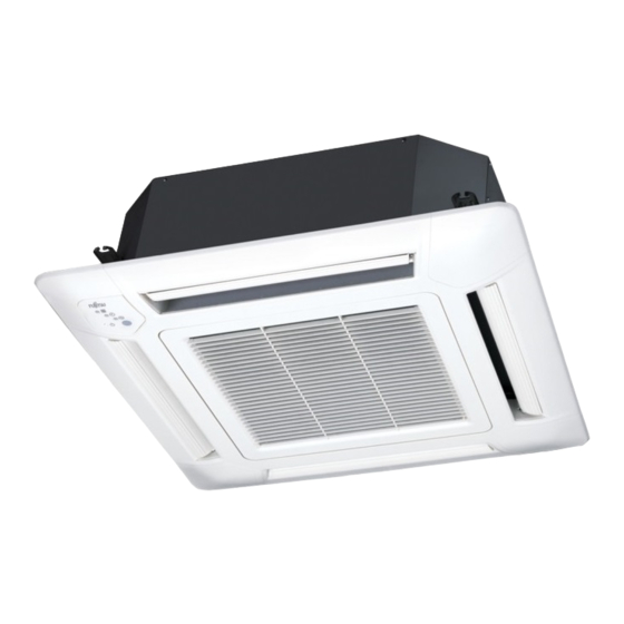
1. INDOOR UNIT CASSETTE TYPE : G12LVLB G14LVLB G18LVLB G24LVLA DTR_AU047E_02 2013.02.28... -
Page 3: Table Of Contents
CONTENTS 1. INDOOR UNIT 1. FEATURES ......................01 - 01 2. REMOTE CONTROLLER ................01 - 03 3. SPECIFICATIONS ....................01 - 05 4. DIMENSIONS ......................01 - 07 5. WIRING DIAGRAMS ..................01 - 09 6. CAPACITY TABLE .................... 01 - 10 6-1. -
Page 4: Features
FEATURES MODEL AU G12LVLB / AO G12LALL AU G14LVLB / AO G14LALL AU G18LVLB / AO G18LALL AU G24LVLA / AO G24LALA FEATURES Energy efficiency class MODEL AU G12LVLB AU G14LVLB AU G18LVLB AU G24LVLA Cooling Heating Quiet quality 2-stage turbo fan Optimization of wing form (laminar High efficiency design by 2 stage structure wing type) and wing number (7 blades... - Page 5 10°C HEAT Operation *Only available with Wireless RC. The room temperature can be set to go no lower than 10°C, thus ensuring that the room does not get too cold when not occupied. Caution) • When the room temperature is higher than 10°C, “ 10°C HEAT”...
-
Page 6: Remote Controller
REMOTE CONTROLLER WIRELESS REMOTE CONTROLLER FEATURES 4 mode timer setup available (ON / OFF / PROGRAM / SLEEP) Easy operation. Easy to change signal code (max. 4 units) by button operation. Simple function setting Setting of the air conditioner selection function is performed by remote controller. Built-in timers Select from four different timer programs (ON / OFF / PROGRAM / SLEEP). - Page 7 FUNCTIONS MODE button Selects the operating mode (AUTO, COOL, DRY, FAN, HEAT). /Start / end R.C. signal code change. (Max 4 types) 10°C HEAT button SET TEMP. button ( ▲ / ▼ ) Sets the indoor temp./ Sets R.C. signal code. ECONOMY button SLEEP button Pressed to select sleep timer.
-
Page 8: Specifications
SPECIFICATIONS CASSETTE MODEL Type INVERTER HEATPUMP Indoor unit AU G12LVLB AU G14LVLB AU G18LVLB AU G24LVLA Model name Outdoor unit AO G12LALL AO G14LALL AO G18LALL AO G24LALA Power source 230V ~ 50Hz Available voltage range 198-264V ~ 50Hz 3.50 4.30 5.20 6.80... - Page 9 Model name AU G12LVLB AU G14LVLB AU G18LVLB AU G24LVLA Cooling Energy efficiency class Heating (Average) Cooling 3.5 (35°C) 4.3 (35°C) 5.2 (35°C) 6.8 (35°C) Pdesign Heating (Average) 4.2 (-10°C) 4.5 (-10°C) 5.2 (-10°C) 6.0 (-10°C) SEER Cooling 6.20 6.40 6.20 5.60 kWh/kWh...
-
Page 10: Dimensions
DIMENSIONS MODEL : AU G12LVLB, AU G14LVLB, AU G18LVLB, AU G24LVLA Unit : mm • Cassette grille mounting state 530: Hanging bolt position op view Be sure to leave Service access service access for future service at the designated position. Min. - Page 11 INSTALLATION PLACE Unit : mm Strong and durable ceiling or more 1000 1000 or more or more 1800 or more Obstruction Floor H (The maximum height from floor to ceiling) Unit: mm Model name AU G12LVLB AU G14LVLB AU G18LVLB AU G24LVLA Standard mode 2700...
-
Page 12: Wiring Diagrams
WIRING DIAGRAMS MODEL : AU G12LVLB, AU G14LVLB, AU G18LVLB, AU G24LVLA - (01 - 09) -... -
Page 13: Capacity Table
CAPACITY TABLE 6-1. COOLING CAPACITY This table is created using the maximum capacity. MODEL : AU G12LVLB 10.0 Indoor temperature °CDB °CWB °CDB 3.47 2.59 0.29 3.87 2.61 0.30 4.00 2.83 0.30 4.26 2.84 0.30 4.40 3.07 0.30 4.66 3.06 0.31 4.92 3.26... - Page 14 MODEL : AU G24LVLA 15.5 Indoor temperature °CDB °CWB °CDB 5.62 4.52 0.60 6.26 4.54 0.60 6.47 4.94 0.61 6.90 4.95 0.61 7.11 5.35 0.62 7.54 5.33 0.62 7.96 5.68 0.63 5.52 4.47 0.64 6.15 4.49 0.65 6.36 4.89 0.66 6.78 4.90 0.66...
-
Page 15: Heating Capacity
6-2. HEATING CAPACITY This table is created using the maximum capacity. MODEL : AU G12LVLB 10.0 Indoor temperature °CDB °CDB °CWB 3.76 1.87 3.67 1.91 3.58 1.95 3.49 1.99 3.40 2.03 4.26 1.87 4.16 1.91 4.06 1.95 3.96 1.99 3.86 2.03 4.69 2.13... - Page 16 MODEL : AU G24LVLA 15.5 Indoor temperature °CDB °CDB °CWB 6.15 2.84 6.01 2.90 5.86 2.96 5.72 3.01 5.57 3.07 6.92 3.03 6.75 3.09 6.59 3.15 6.42 3.22 6.26 3.28 7.64 3.02 7.45 3.08 7.27 3.14 7.09 3.20 6.91 3.27 8.59 3.00 8.38...
-
Page 17: Fan Performance
FAN PERFORMANCE 7-1. AIR VELOCITY DISTRIBUTION Note: Condition MODEL : AU G12LVLB Fan speed : High Operation mode : Fan 4-way air outlet Ceiling mode : Standard Unit : m/s 0.25 0.25 0.25 0.25 TOP VIEW VERTICAL LOUVER : Upward Unit : m/s 0.25 0.25... - Page 18 Note: Condition Fan speed : High Operation mode : Fan 3-way air outlet Ceiling mode : Standard Unit : m/s 0.25 0.25 0.25 TOP VIEW VERTICAL LOUVER : Upward Unit : m/s SIDE VIEW 0.25 VERTICAL LOUVER 0.25 : Upward Unit : m/s 0.25 0.25...
- Page 19 Note: Condition MODEL : AU G14LVLB Fan speed : High Operation mode : Fan 4-way air outlet Ceiling mode : Standard Unit : m/s 0.25 0.25 0.25 0.25 TOP VIEW VERTICAL LOUVER : Upward Unit : m/s 0.25 0.25 SIDE VIEW VERTICAL LOUVER : Upward Unit : m/s...
- Page 20 Note: Condition Fan speed : High Operation mode : Fan 3-way air outlet Ceiling mode : Standard Unit : m/s 0.25 0.25 0.25 TOP VIEW VERTICAL LOUVER : Upward Unit : m/s SIDE VIEW 0.25 0.25 VERTICAL LOUVER : Upward Unit : m/s SIDE VIEW VERTICAL LOUVER...
- Page 21 Note: Condition MODEL : AU G18LVLB Fan speed : High Operation mode : Fan 4-way air outlet Ceiling mode : Standard Unit : m/s 0.25 0.25 0.25 0.25 TOP VIEW VERTICAL LOUVER : Upward Unit : m/s 0.25 0.25 SIDE VIEW VERTICAL LOUVER : Upward Unit : m/s...
- Page 22 Note: Condition Fan speed : High Operation mode : Fan 3-way air outlet Ceiling mode : Standard Unit : m/s 0.25 0.25 0.25 TOP VIEW VERTICAL LOUVER : Upward Unit : m/s SIDE VIEW 0.25 0.25 VERTICAL LOUVER : Upward Unit : m/s SIDE VIEW 0.25...
- Page 23 Note: Condition MODEL : AU G24LVLA Fan speed : High Operation mode : FAN 4-way air outlet Ceiling mode : Standard Unit : m/s 0.25 0.25 0.25 0.25 TOP VIEW VERTICAL FLAP : Upward Unit : m/s 0.25 SIDE VIEW 0.25 VERTICAL FLAP : Upward...
- Page 24 Note: Condition MODEL : AU G24LVLA Fan speed : High Operation mode : FAN 3-way air outlet Ceiling mode : Standard Unit : m/s 0.25 0.25 0.25 TOP VIEW VERTICAL FLAP : Upward Unit : m/s SIDE VIEW 0.25 0.25 VERTICAL FLAP : Upward Unit : m/s...
-
Page 25: Airflow
7-2. AIRFLOW 7-2-1. STANDARD CEILING MODE MODEL : AU G12LVLB Cooling Number of Fan speed rotations Airflow (r.p.m) HIGH QUIET Heating Number of Fan speed rotations Airflow (r.p.m) HIGH QUIET - (01 - 22) -... - Page 26 MODEL : AU G14LVLB Cooling Number of Fan speed rotations Airflow (r.p.m) HIGH QUIET Heating Number of Fan speed rotations Airflow (r.p.m) HIGH QUIET - (01 - 23) -...
- Page 27 MODEL : AU G18LVLB Cooling Number of Fan speed rotations Airflow (r.p.m) HIGH QUIET Heating Number of Fan speed rotations Airflow (r.p.m) HIGH QUIET - (01 - 24) -...
- Page 28 MODEL : AU G24LVLA Cooling Number of Fan speed rotations Airflow (r.p.m.) HIGH QUIET Heating Number of Fan speed rotations Airflow (r.p.m.) HIGH QUIET - (01 - 25) -...
- Page 29 7-2-2. HIGH CEILING MODE MODEL : AU G12LVLB Cooling Number of Fan speed rotations Airflow (r.p.m) HIGH QUIET Heating Number of Fan speed rotations Airflow (r.p.m) HIGH QUIET - (01 - 26) -...
- Page 30 MODEL : AU G14LVLB Cooling Number of Fan speed rotations Airflow (r.p.m) HIGH QUIET Heating Number of Fan speed rotations Airflow (r.p.m) HIGH QUIET - (01 - 27) -...
- Page 31 MODEL : AU G18LVLB Cooling Number of Fan speed rotations Airflow (r.p.m) HIGH QUIET Heating Number of Fan speed rotations Airflow (r.p.m) HIGH QUIET - (01 - 28) -...
- Page 32 MODEL : AU G24LVLA Cooling Number of Fan speed rotations Airflow (r.p.m.) 1030 HIGH 1050 QUIET Heating Number of Fan speed rotations Airflow (r.p.m.) 1000 HIGH 1030 QUIET - (01 - 29) -...
-
Page 33: Operation Noise
OPERATION NOISE 8-1. NOISE LEVEL CURVE MODEL : AU G12LVLB Cooling Heating NC-65 NC-65 NC-60 NC-60 NC-55 NC-55 NC-50 NC-50 NC-45 NC-45 NC-40 NC-40 HIGH HIGH NC-35 NC-35 NC-30 NC-30 NC-25 NC-25 QUIET NC-20 NC-20 QUIET NC-15 NC-15 1,000 2,000 4,000 8,000 1,000... - Page 34 MODEL : AU G18LVLB Cooling Heating NC-65 NC-65 NC-60 NC-60 NC-55 NC-55 NC-50 NC-50 NC-45 NC-45 NC-40 NC-40 NC-35 NC-35 NC-30 NC-30 NC-25 NC-25 NC-20 NC-20 NC-15 NC-15 1,000 2,000 4,000 8,000 1,000 2,000 4,000 8,000 Octave band center frequency,Hz Octave band center frequency,Hz MODEL : AU G24LVLA Cooling...
-
Page 35: Sound Level Check Point
8-2. SOUND LEVEL CHECK POINT Microphone Microphone - (01 - 32) -... -
Page 36: Electric Characteristics
ELECTRIC CHARACTERISTICS Model Name AU G12LVLB AU G14LVLB AU G18LVLB AU G24LVLA Voltage 230 ~ Power Supply Frequency Max Operating Current 0.24 0.28 0.38 0.30 Connection Cable *1) Wiring Spec. Limited wiring length *1) Wiring Spec. Selected Sample (Selected based on Japan Electrotechnical Standard and Codes Committee E0005) - (01 - 33) -... -
Page 37: Safety Devices
SAFETY DEVICES Model Protection form AU G12LVLB AU G14LVLB AU G18LVLB AU G24LVLA Circuit protection Current fuse (PCB) 250V 3.15A Thermal protection 138 ± 15 °C OFF Fan motor protection program 105 ± 20 °C ON - (01 - 34) -... -
Page 38: External Input & Output
EXTERNAL INPUT & OUTPUT Connector INPUT OUTPUT REMARKS CN102 Control input — See external CN103 — Operation status output input/output settings for details. — Fresh air control output 11-1. EXTERNAL INPUT CONTROL INPUT (Operation/Stop or Forced stop) The air conditioner can be remotely operated by means of the following on-site work. "Operation/Stop"... -
Page 39: External Output
11-2. EXTERNAL OUTPUT OPERATION STATUS OUTPUT An air conditioner operation status signal can be output. Circuit diagram example Indoor Connected unit control PC board Connector Ex.)Relay unit Ex.)Display 24V DC Relay power supply *10 m Signal Field supply * Make the distance from the PC board to the connected unit within 10m. Relay spec. - Page 40 FRESH AIR CONTROL OUTPUT A signal linked to air conditioner indoor fan ON can be output. * However, signal becomes OFF during cold air prevention control operation. Circuit diagram example Indoor Connected unit control PC board Ex.) Fan Ex.) Relay unit 12 V Connector Relay...
-
Page 41: Function Settings
FUNCTION SETTINGS 12-1. INDOOR UNIT INDOOR UNIT DIP SW Remote controller address setting Jumper Wire Setting forbidden SWITCH POSITION MAIN PCB Indoor unit Printed circuit board DIP-SW SETTING Remote controller address setting A number of indoor units can be operated at the same time using a wired remote controller. Set the unit number of each indoor unit using the DIP switches on the indoor unit circuit board. -
Page 42: Indoor Unit (Setting By Remote Controller)
12-2. INDOOR UNIT (Setting by remote controller) • The function settings of the control of the indoor unit can be changed by this procedure according to the installation conditions. Incorrect settings can cause the indoor unit to malfunction. • After the power is turned on, perform the “FUNCTION SETTING” according to the installation conditions using the remote controller. - Page 43 CONTENTS OF FUNCTION SETTING • Follow the instructions in the Local Setup Procedure, which is supplied with the remote control, in accordance with the installed condition. After the power is turned on, perform the Function Setting on the remote control. •...
- Page 44 4) Cooler room temperature correction Depending on the installed environment, the room temperature sensor may require a correction. The settings may be selected as shown in the table below. ( . . .Factory setting) Setting Description Function Number Setting Value Standard Slightly lower control Lower control...
- Page 45 10) Indoor unit fan control for energy saving (Only cooling mode) Enable or disable indoor unit fan control when the outdoor unit is stopped. ( . . .Factory setting) Setting Description Function Number Setting Value *If setting value is “00”: When the outdoor unit is stopped, the indoor unit fan operates following the setting on the remote controller continuously.
- Page 46 REMOTE CONTROLLER SIGNAL CODE SETTING Use the following steps to select the signal code of the remote controller. (Note that the air conditioner cannot receive a signal code if the air conditioner has not been set for the signal code.) 1.
-
Page 47: Optional Parts
OPTIONAL PARTS 13-1. CONTROLLER Exterior Parts name Model No. Summary Large and full-dot liquid crystal Wired Remote screen, wide and large keys UTY-RVN M Controller easy to press, user-intuitive arrow key. Wired remote Unit control is performed by UTY-RNN M controller wired remote controller Simple remote... -
Page 48: Others
13-3. OTHERS Exterior Parts name Model No. Summary Air outlet shutter plate is installed Air outlet UTR-YDZB at the air outlet when 3-way shutter plate direction is performed. Insulation Install when the under roof Insulation kit condition is expected to be UTZ-KXGC for high humidity the humidity of over 80 % and... - Page 49 2. OUTDOOR UNIT SINGLE TYPE : AO G12LALL AO G14LALL AO G18LALL AO G24LALA DTR_AO099E_02 2013.02.28...
- Page 50 CONTENTS 2. OUTDOOR UNIT 1. SPECIFICATIONS ....................02 - 01 2. DIMENSIONS ......................02 - 02 3. REFRIGERANT CIRCUIT ................02 - 03 4. WIRING DIAGRAMS ..................02 - 04 5. CAPACITY COMPENSATION RATE FOR PIPE LENGTH AND HEIGHT DIFFERENCE ..............
-
Page 51: Specifications
SPECIFICATIONS Type INVERTER HEAT PUMP Model name AO G12LALL AO G14LALL AO G18LALL AO G24LALA Power source 230V ~ 50Hz Available voltage range 198 - 264V ~ 50Hz Starting current Cooling 1780 1910 2000 2470 Airflow rate Heating 1630 1740 1910 2470 Type ×... -
Page 52: Dimensions
DIMENSIONS MODEL : AO G12LALL, AO G14LALL, AO G18LALL, AO G24LALA (Unit : mm) Top view Front view AO G12LALL AO G24LALA AO G14LALL AO G18LALL Air flow Side view Bottom view INSTALLATION PLACE When there are obstacles at When there are obstacles at When there are obstacles at the the back or front sides. -
Page 53: Refrigerant Circuit
REFRIGERANT CIRCUIT MODEL : AO G12LALL, AO G14LALL, AO G18LALL, AO G24LALA Refrigerant pipe diameter Liquid : 1/4" (6.35 mm) Gas : 3/8" (9.52 mm) : AO*G12LALL 1/2" (12.70 mm) : AO*G14LALL, AO*G18LALL 5/8" (15.88 mm) : AO*G24LALA - (02 - 03) -... -
Page 54: Wiring Diagrams
WIRING DIAGRAMS MODEL : AO G12LALL, AO G14LALL, AO G18LALL - (02 - 04) -... - Page 55 MODEL : AO G24LALA - (02 - 05) -...
-
Page 56: Capacity Compensation Rate For Pipe Length And Height Difference
CAPACITY COMPENSATION RATE FOR PIPE LENGTH AND HEIGHT DIFFERENCE This table is created using the maximum capacity. MODEL : AO G12LALL Pipe length (m) COOLING 0.903 0.894 0.867 0.964 0.918 0.909 0.881 Indoor unit is higher than 0.988 0.968 0.922 0.912 0.885 outdoor unit. - Page 57 This table is created using the maximum capacity. MODEL : AO G14LALL Pipe length (m) COOLING 0.953 0.950 0.947 0.983 0.968 0.966 0.962 Indoor unit is higher than 0.988 0.987 0.972 0.970 0.966 outdoor unit. 0.992 0.992 0.991 0.976 0.974 0.970 Height difference H...
- Page 58 This table is created using the maximum capacity. MODEL : AO G18LALL Pipe length (m) COOLING 0.953 0.950 0.947 0.983 0.968 0.966 0.962 Indoor unit is higher than 0.988 0.987 0.972 0.970 0.966 outdoor unit. 0.992 0.992 0.991 0.976 0.974 0.970 Height difference H...
- Page 59 This table is created using the maximum capacity. MODEL : AO G24LALA Pipe length (m) COOLING 0.963 0.961 0.959 0.984 0.981 0.979 0.977 0.975 Indoor unit is higher than 0.988 0.988 0.985 0.983 0.981 0.979 outdoor unit. 0.992 0.992 0.992 0.989 0.987 0.985...
-
Page 60: Additional Charge Calculation
ADDITIONAL CHARGE CALCULATION MODEL : AO G12LALL Refrigerant type R410A Refrigerant amount 1150 Refrigerant charge Total pipe length 15 or less 25 (MAX) 20g/m Additional charge MODEL : AO G14LALL, AO G18LALL Refrigerant type R410A Refrigerant amount 1250 Refrigerant charge Total pipe length 15 or less 25 (MAX) -
Page 61: Airflow
AIRFLOW MODEL : AO G12LALL Cooling Number of rotations Airflow (r.p.m.) 1780 1048 Heating Number of rotations Airflow (r.p.m.) 1630 MODEL : AO G14LALL Cooling Number of rotations Airflow (r.p.m.) 1910 1124 Heating Number of rotations Airflow (r.p.m.) 1740 1024 - (02 - 11) -... - Page 62 MODEL : AO G18LALL Cooling Number of rotations Airflow (r.p.m.) 2000 1177 Heating Number of rotations Airflow (r.p.m.) 1910 1124 MODEL : AO G24LALA Cooling Number of rotations Airflow (r.p.m.) 2470 1050 1454 Heating Number of rotations Airflow (r.p.m.) 2470 1050 1454 - (02 - 12) -...
-
Page 63: Operation Noise (Sound Pressure)
OPERATION NOISE (SOUND PRESSURE) 8-1. NOISE LEVEL CURVE MODEL : AO G12LALL Cooling Heating NC-65 NC-65 NC-60 NC-60 NC-55 NC-55 NC-50 NC-50 NC-45 NC-45 NC-40 NC-40 NC-35 NC-35 NC-30 NC-30 NC-25 NC-25 NC-20 NC-20 NC-15 NC-15 1,000 2,000 4,000 8,000 1,000 2,000 4,000... - Page 64 MODEL : AO G18LALL Cooling Heating NC-65 NC-65 NC-60 NC-60 NC-55 NC-55 NC-50 NC-50 NC-45 NC-45 NC-40 NC-40 NC-35 NC-35 NC-30 NC-30 NC-25 NC-25 NC-20 NC-20 NC-15 NC-15 1,000 2,000 4,000 8,000 1,000 2,000 4,000 8,000 Octave band center frequency,Hz Octave band center frequency,Hz MODEL : AO G24LALA Cooling...
-
Page 65: Sound Level Check Point
8-2. SOUND LEVEL CHECK POINT Airflow - (02 - 15) -... -
Page 66: Electric Characteristics
ELECTRIC CHARACTERISTICS Model name AO G12LALL AO G14LALL AO G18LALL AO G24LALA Voltage 230 ~ Power supply Frequency *1) Max operating current 10.0 12.5 13.5 Starting Current Main Fuse (Circuit breaker) *2) Wiring Spec. Current Power Cable *1) The maximum current is the total current of indoor unit and outdoor unit. *2) Wiring Spec.: Selected Sample (Selected based on Japan Electrotechnical Standards and Codes Committee E0005) -
Page 67: Safety Devices
SAFETY DEVICES Model Protection form AO G12LALL AO G14LALL AO G18LALL AO G24LALA 250V 20A Current fuse (Near the terminal) 250V 5A Circuit protection Current fuse 250V 15A (Main printed 250V 3.15A circuit board) Fan motor Thermal protection OFF : 100 °C OFF : 110 °C...
Need help?
Do you have a question about the AUG12LVLB and is the answer not in the manual?
Questions and answers