
Related Manuals for Stirling RecoupAerator SD-95+


Summary of Contents for Stirling RecoupAerator SD-95+
- Page 1 RecoupAerator SD-95+ ® Energy Recovery Ventilator Owner’s Manual and Installation Guide Stirling Technology, Inc. 178 Mill Street Athens, Ohio 45701 www.healthyairpeople.com 1-800-535-3448...
-
Page 2: Table Of Contents
Stirling Technology, Inc. TABLE OF CONTENTS Section 1: Owner’s Manual Introduction......................3 Features........................3 Specifications ......................4 General Information....................4 Service and Maintenance ..................5 Troubleshooting Guide ...................7 Replacement Parts ....................8 Control Options, Vent Hoods and Mounting Kits ..........10 Wiring Diagram .......................11 Section 2: Installation Guide Installation .......................12... -
Page 3: Section 1: Owner's Manual
Stirling Technology, Inc. RecoupAerator SD-95+ ® Section 1: Owner’s Manual Introduction: ® Your RecoupAerator is designed to bring fresh air in to the home while simultaneously exhausting stale air. The heat (or coolness) of the air being exhausted is ®... -
Page 4: Specifications
Stirling Technology, Inc. ____________________________________________ Specifications: ® Model: RecoupAerator SD-95+ Energy Recovery Ventilator. Includes patented Rotary Heat Exchange Core, filters, fans, and drive motor. Pre-heaters are optionally available. Air Flow Capacity: 197 cfm Sensible Thermal Efficiency: 96% at full flow Heat Exchange Type: Patented Rotary Random Matrix Polymer Filtration: Washable Heat Exchange matrix 95% effective at 5 microns with washable expanded aluminum pre-filter. -
Page 5: Service And Maintenance
Stirling Technology, Inc. Service & Maintenance Before Performing Maintenance ® Before any service to your RecoupAerator is performed, be sure that the unit is switched off and power has been disconnected from the unit. Using the wall mounted variable controller and/or the external on/off switch on the unit does not terminate main power to the unit. - Page 6 Stirling Technology, Inc. Heat Transfer Core ® The RecoupAerator ’s patented Heat Exchange Wheel contains a removable core filtration material (see photo below) that may require washing. To check the core material: ® 1. Disconnect power to the RecoupAerator 2. Open the non-motor side access door (the side labeled “...
-
Page 7: Troubleshooting Guide
Stirling Technology, Inc. -
Page 8: Replacement Parts
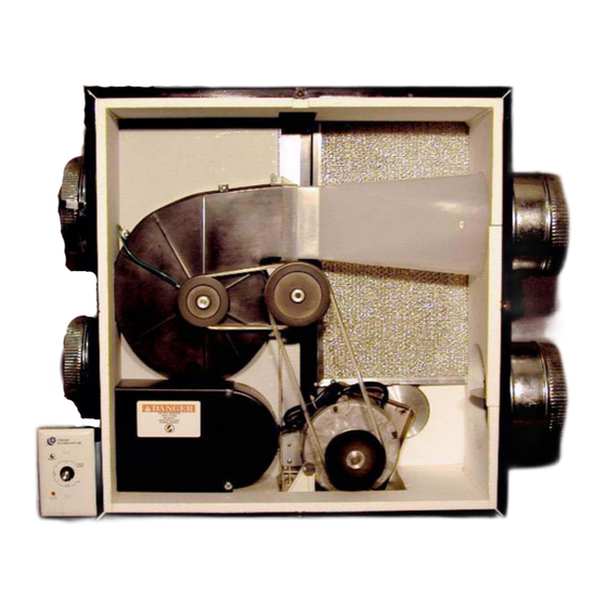
Stirling Technology, Inc. PARTS DIAGRAM FOR THE 95+ ENERGY RECOVERY VENTILATOR (Use when ordering replacement parts) - Page 9 Stirling Technology, Inc. REPLACEMENT PARTS LIST 015 - Small Filter Access Door 016 - Large Filter Access Door 023 - Power Cord 040 - Motor and Controller Can 043 - Fuse Holder and Cap 044 - Small Motor Pulley 103 - Motor Mount...
-
Page 10: Control Options, Vent Hoods And Mounting Kits
Stirling Technology, Inc. CM-02 – Ceiling Mount Kit WM-04 – Wall Mounting Bracket TERMINATION KITS WT-06 – Wall Termination Kit (for 6 inch duct) WT-07 – Wall Termination Kit (for 7 inch duct) WT-08 – Wall Termination Kit (for 8 inch duct) WT-10 –... -
Page 11: Wiring Diagram
Stirling Technology, Inc. -
Page 12: Section 2: Installation Guide
Stirling Technology, Inc. RecoupAerator SD-95+ ® Section 2: Installation Guide Instructions for Licensed Contractors Installation: Note: It is recommended that a licensed HVAC Technician install this product. There are numerous considerations that must be taken in to account when installing a ventilation system, including airflow dynamics and condensation issues. -
Page 13: Installation Dimensions
Stirling Technology, Inc. Installation Dimensions: Allow clearance in marked areas for access to the unit for regular maintenance and servicing. Also, you must leave room on both ends (with collars) to connect ductwork to the unit. - Page 14 Stirling Technology, Inc. Allow clearance in marked areas for access to the unit for regular maintenance and servicing. Also, you must leave room on both ends (with collars) to connect ductwork to the unit.
-
Page 15: Installation Options
Stirling Technology, Inc. Installation Options ® There are three basic ways to install the inside ducts for the RecoupAerator Option 1: Dedicated Ductwork This is the most complete installation option and is ideal for new construction. It should be used when the customer has a specific problem associated with indoor air quality. It is also the only option for homes without forced air heating systems. - Page 16 Stirling Technology, Inc. Option 2: Shared Ductwork Method 1. This method utilizes the existing home HVAC duct system completely. Both ® the stale air removal and the fresh air in ducts from your RecoupAerator will be attached to the cold air return duct of your HVAC system. Be sure to keep at least 3 feet of space along the cold air return line between the two ventilator lines (see diagram).
-
Page 17: Location And Position Of The Recoupaerator
Stirling Technology, Inc. Method 3. This method partially utilizes the existing home HVAC duct system. The fresh ® air in duct from the RecoupAerator gets ducted into the cold air return line of the furnace. A minimum of 3 to 6 foot distance between this line and the furnace is recommended. The ®... - Page 18 Stirling Technology, Inc. ® Horizontal: Use Ceiling Mounting Kit (CM-02) to suspend the RecoupAerator from the ‘D’ rings located on the four corners of the unit (SEE BELOW). The motor side of the unit should be facing the floor. Allow adequate space (12 inches) between the ceiling and the unit to allow for servicing of pulleys and belts.
-
Page 19: Planning The Ductwork
Stirling Technology, Inc. ® Ducting: Ducting between the RecoupAerator and the outdoors (those collars marked CONNECT TO OUTSIDE) and all ducting in unconditioned spaces must be insulated. Use vapor barriers as needed to prevent condensation. Vapor barriers always go on the warm side of a duct. - Page 20 Stirling Technology, Inc. To insure maximum airflow, use the largest practical duct for the installation. Under no circumstances should the trunk duct size be less than 6 inches, as this will restrict the airflow considerably. Insulated flex ducts tend to reduce blower noise levels but add airflow resistance, while galvanized ducts provide least resistance to air flow and are easiest to install properly.
-
Page 21: Installing The Outside Ducts
Stirling Technology, Inc. 8. Final operational duct system to have less than 0.5” w.c. total external static pressure. CAUTION All ducting to the outdoors should be installed above anticipated snow and flood lines and fitted with screened weather caps to prevent bird and insect entry. -
Page 22: Installing The Inside Ducts
Stirling Technology, Inc. Installing the Inside Ducts Location of supply and exhaust vents inside the house is an important factor in ventilation. Consider the following guidelines for maximum effectiveness: 1. The air exhaust point should be located high in the room, as far as possible from the point of air entry. - Page 23 Stirling Technology, Inc. 5. Use included crimp style wire nuts to connect the other end of the controller wire to the exposed ends on the back of the controller. Make sure to match colors as you did on the unit.
- Page 24 Stirling Technology, Inc. Wiring to the Furnace If the RecoupAerator is being installed to utilize the forced air ductwork (option 3), then it must be used in conjunction with the furnace/AC air handler. The purpose of operating the ...
-
Page 25: System Start-Up And Run Test
Stirling Technology, Inc. System Start-Up and Run Test Once installation is complete, you can make a final check of all system components to ensure that everything is operating properly. To do this: 1. Open the motor side access door. ®... -
Page 26: Filter Light
Stirling Technology, Inc. is complete will yield inaccurate results. To balance the airflow, a manometer is needed (optional accessory). There are four balancing ports on top of the SD-95+ unit, one set beside each filter access door, marked IN and OUT. These ports should remain plugged except when balancing airflow. -
Page 27: General Warranty Information
Stirling Technology, Inc. The “check filter” indicator light is located on the front side of the controller and will light after a continuous operation of 90 days (24 hrs/day, 7 days a week approximately). Due to differences in indoor and outdoor environments, your filters may or may not be in need of cleaning at this interval.
Need help?
Do you have a question about the RecoupAerator SD-95+ and is the answer not in the manual?
Questions and answers