
Related Manuals for Lumag G3E

Summary of Contents for Lumag G3E
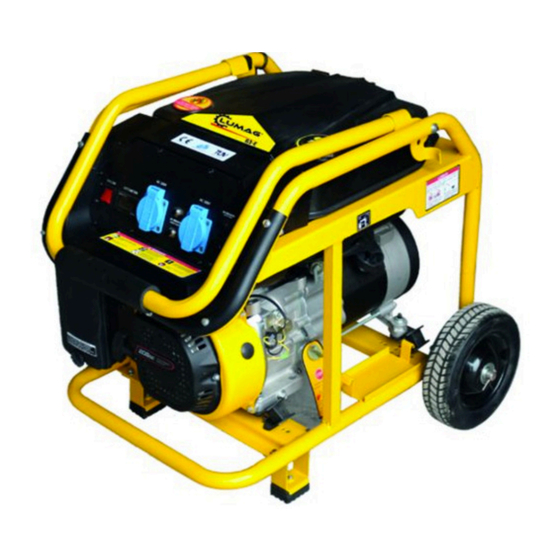
- Page 1 Distribution Limited 3 kw Petrol Generator Operator’s Manual FOR YOUR SAFETY READ AND UNDERSTAND THE ENTIRE MANUAL BEFORE OPERATING THIS MACHINE...
- Page 3 For the warranty to be valid the Warranty Registration Form must be completed and returned to Lumag Distribution Limited within 14 days of the purchase, together with a copy of the purchase invoice. We will use your email to confirm that we have received the completed Warranty Registration Form and contact you about any errors or omissions on the form.
- Page 5 All Other Moving Parts & Lubricate X (2) Cables 1 – First service only, 2 = Should be carried out by your Lumag Dealer, 3 = May need to be done more often in dusty areas & 4 = Replace paper element only...
- Page 9 PREFACE Thank you for choosing the gasoline generator set of our company. Based on the latest technology at home and abroad, our Company. has successfully developed the gasoline generator set. The unit is characterized by advanced design, compact structure, reliable performance, convenient service, low fuel consumption and noise as well as fashionable shape.
- Page 10 IMPORTANT NOTICES Please pay special attention to statements preceded by the following words: WARNING: A warning is used to alert the user to fact that hazardous operating and maintenance procedures may result in injury to or death of personnel if not strictly observed. CAUTION: A caution is used to alert the user to fact that hazardous operation and maintenance procedures may result in injury to or death of personnel if not strictly observed.
-
Page 11: Table Of Contents
Contents 1.Specifications ………………………………………………………………………………………… 1 2.Generator Safety……………………………………………………………………………………………5 3. Introduction to Parts and Components ……………………………………………………………………7 4. Pre-operation Inspection …………………………………………………………………………………8 5. Starting the Engine…………………………………………………………………………………………12 6. Service………………………………………………………………………………………………………14 7. Stopping the Engine ………………………………………………………………………………………19 8. Maintenance ………………………………………………………………………………………………20 9. Storage ……………………………………………………………………………………………………24 10. Troubleshooting……………………………………………………………………………………………26 11.Assembly of parts…………………………………………………………………………………………28 12. Wiring Diagram …………………………………………………………………………………………30... -
Page 12: Specifications
1. Specification Rated Output 1.0KW 1.5KW 2.0KW 2.5KW 2.8KW 5.0KW 6.0KW 7.0KW Item 192F Engine 156F 168F 170F 170F 170F 188F 190F 16.5 EngineRated Power(HP) 13.0 15.0 Displacenent(ml) 4-stoke OHV single-cylinder gasoline engine with forced air-cooled Engine Model Engine Rated 3000/3600 Rotate Speed(rpm) Voltage Adjust Type... -
Page 13: Generator Safety
2. GENERATOR SAFETY 1.1 Never operate it in an enclosed room. Fig.3 Fig.1 1.2 Never connect to home circuit. Fig.2 Fig.4... - Page 14 1.3 Do not operate it under wet circumstances. 1.4 Place inflammable away from the unit at least one meter. 1.5 No smoking when filling fuel. Fig.5 Fig.6 1.6 Always fill fuel after stopping it. Fig.7 1.7 Do not spill out when filling fuel.
-
Page 15: Introduction To Parts And Components
3.INTROUCITON TO PARTS AND COMPONENTS Main components of the unit are located as follows. 1.Fuel sensor 2. Fuel filler cap 3. AC plug socket 4. AC breaker 5. Voltmeter 6. Dipstick 7. Ignition switch 8. Drain plug 9. Starting handle 10. -
Page 16: Pre-Operation Inspection
4. PRE-OPERATION INSPECTION 4.1 ENGINE-OIL LEVEL NOTE: always check the generator in the case of stopping the generator on a level ground. 3. In the case that the oil 1. Turn out the oil ever is below the lower filler cap and clean level mark of the dipstick, the dipstick with fill oil to the upper level... - Page 17 4.2 FUEL LEVEL 1. Open the fuel filler cap. 3. Check the fuel level, and fill fuel if necessary. Fig.15 Fig.13 2. Fill fuel to the shoulder of the filter. 4. Reinstall the fuel filler cap well. Fig.16 Fig.14...
- Page 18 4.3 AIR CLEANER 1. Remove the clip and dismantle the air housing 4. Put the filter element in to the original position, 2. Check and make sure the air cleaner core is intact install the cover and secure it well. and clean.
- Page 19 4.4 BATTERY Check and make sure that the electrolyte level of each battery cell is between is upper and lower level marks. Fig.20 1. upper level mark 2. lower lever mark...
-
Page 20: Starting The Engine
5. STARTING THE GENERATOR 5.1 Remove all loads from AC socket. 5.4 Set the choke lever to OFF position. 5.2 Switch off AC breaker. Don’t close the choke when starting the engine in hot condition. Fig.23 Fig.21 5.3 Turn on the fuel cock. Fig.22... - Page 21 5.5 Turn on the ignition switch . 5.7 Once the engine is warmed up, set the choke lever to ON position. Fig.24 Fig.26 Recoil Electric Start Start 5.6 Pull the start handle gently until feeling an anti-action, and then pull it up strongly. WARNING After starting up, release the starting lever slightly so avoid injuring personnel or damaging equipment due to its bouncing back.
-
Page 22: Service
6. SERVICE Always do as the following so as to keep the generator in a sound condition. WARNING 6.1 Always connect the generator to the earth to prevent misusing. Fig.27... - Page 23 6.2. The following table gives reference information for connection the electric appliances to generator. Wattage Example Description Typified Start Rating Electric device Start Rating Incandescent lamp Incandescent lamp ● Incandescent lamp 100VA 100VA ×1 ×1 ● Heating device 100W Fluorescent lamp Fluorescent lamp 80VA 60VA...
- Page 24 6.3. If the generator is to supply two or above loads with power supply, be sure to connect them one by with higher start current first. Fig.28...
- Page 25 6.4 Connecting methods illustrated as follows. a) Correct c) Correct b) Forbidden Fig.29 WARNING When connect the generator to home power supply, be sure that a skilled electrician does this job. Improper connecting between the generator and loads may cause damage to the generator, even a fire.
- Page 26 6.5 USE INSTRUCTION WHEN PROVIDING 5.3 Switch on the AC breaker. ALTERATIVE CURRENT SUPPLY 5.1 Start the generator Fig.30 Fig.32 5.2 Connect devices. Fig.31...
-
Page 27: Stopping The Engine
7. STOPING THE ENGINE 7.3 Set the fuel cock to off. 7.1 Switch off AC breaker. Fig.33 Fig.35 7.2 Turn the ignition switch to OFF. NOTE: To stop the generator in an emergency, turn the ignition switch to OFF. Fig.34... -
Page 28: Maintenance
8. MAINTERNANCE User should service the unit according to the Maintenance Schedule as follows: PERIOD ITEM Or first Or every Or every Or every one month 3 months 6 months Year Ref. page Engine oil check Check Replacing engine Replace Replace Air cleaner check Check... - Page 29 8.1 REPLACEMENT OF ENGINE OIL 1 Turn and then take out the dipstick. Fig.36 Fig.37 2. Unscrew the drain plug, and empty the engine oil from the crankcase. 3. Screw on the drain plug. 4. Fill engine oil to the upper level mark of the dipstick. Engine oil recommended: 4-stroke gasoline engine oil –...
- Page 30 8.2 SPARK PLUG 1. Withdraw the spark plug cap from the spark plug. 4. Check the spark plug gap and adjust it if necessary. The gap should be 0.7~0.8mm. Fig.38 Fig.41 2. Dismantle the spark plug by means of a special tool.
- Page 31 8.3 MAINITENANCE OF FUEL FILTER CUP 1. Set the fuel cock to OFF, and disdmantle the fuel 3. Fit the fuel filter cup and gauze to the original filter cup and gauze. position. 2. Fit the fuel filter cup gauze to the original position. Fig.43 Fig.44...
-
Page 32: Storage
9. STORAGE Before long – term storage of the generator which are not kept in use, carry out procedures as follows. 9.1 Empty the fuel the fuel tank. 9.2 wash the fuel filter cup and gauze, install them to 9.4 Turn off the oil filter cap and oil drain plug, and the original position. - Page 33 9.5 Reinstall the oil drain plug, fill engine oil to the 9.6 Pull up the handle gently until feeling an upper level mark of the dipstick, followed by fitter cap anti-action. to the original position. Fig.48 Fig.49 9.7 Place the generator set in the clean place. Fig.50...
-
Page 34: Troubleshooting
10. TROUBLESHOOTHING 3. Check the fuel inside tank. 10.1 TROUBLE: the generator fails to start. Fig.54 Fig.51 4. Remove the spark plug, and check it for proper 1. Check to see if the ignition switch is at ON. sparks. Fig.52 Fig.55 5. - Page 35 10.2 TROUBLE: the unit fails to generate electricity. 2. Check AC breaker is at ON. 1. Check the light bulb. Fig.57 Fig.58 3. If such check is still unsatisfactory, see your dealer for help. Fig.59...
-
Page 36: Assembly Of Parts
11. ASSEMBLY OF PARTS 11.1 WHEEL Assemble the wheel, to this end: 1. Fit the wheel onto the axle, then secure them with washer and split pin. 2. Mount the assembled axle on the frame with bolt and nut. 1. Inner side 2. - Page 37 11.2 BATTERY To install the battery, proceed as follows; 10.2.1 Assemble the battery with nuts, bolts and washers. 10.2.2 Connect the starting cable to the starting motor terminal alone the bottom of the fuel tank. 10.2.3 Connect the earth line with line with the rear end of the generator.
- Page 42 Distribution Limited PART DRAWINGS FOR YOUR SAFETY READ AND UNDERSTAND THE ENTIRE MANUAL BEFORE OPERATING THIS MACHINE...
- Page 44 Unit 10, Hatchmoor Industrial Estate, Hatherleigh, Okehampton, Devon EX20 3LP www.lumag-gb.co.uk 01837 811741 Lumag Distribution Limited Company Number: 09267547 VAT Number: GB154566788 Hatherleigh Plant and Tool Hire is a trading name of Lumag Distribution LTD...
Need help?
Do you have a question about the G3E and is the answer not in the manual?
Questions and answers