Table of Contents
Advertisement
Quick Links
Advertisement
Table of Contents

Related Manuals for Altos R380 F5


Summary of Contents for Altos R380 F5
- Page 1 R380 F5 USER’S MANUAL Revision 1.0...
- Page 2 Release Date: April 30, 2021 Unless you request and receive written permission from Altos Computer, Inc., you may not copy any part of this document. Information in this document is subject to change without notice. Other products and companies referred...
-
Page 3: About This Manual
Preface Preface About this Manual This manual is written for professional system integrators and PC technicians. It provides information for the installation and use of the server. Installation and maintenance should be performed by experienced technicians only. Warnings Special attention should be given to the following symbols used in this manual. Warning! Indicates important information given to prevent equipment/property damage or personal injury. - Page 5 Chapter 1: Introduction Chapter 1 Introduction 1.1 Overview This chapter provides a brief outline of the functions and features of the R380 F5. The following provides an overview of the specifications and capabilities. System Overview Motherboard Chassis 829U3TS-R1K22P-T Processor Dual P+ (LGA4189) sockets 3rd Gen Intel Xeon Scalable...
-
Page 6: Configuration Options
Chapter 1: Introduction Configuration Options Ultra Riser Cards Ultra Riser cards provide network connections and other capabilities. The customer must choose one when purchasing the system. Ultra Riser Networking Options LAN Ports Part Number Description AOC-2UR668G4 No NIC Two PCIe 4.0 x16 and PCIe 4.0x8 (in x16, internal) Two RJ45, Intel X710-AT2, PCIe 4.0 x8 (in x16, Internal), Two 10GBaseT AOC-2UR68G4-i2XT... -
Page 7: System Features
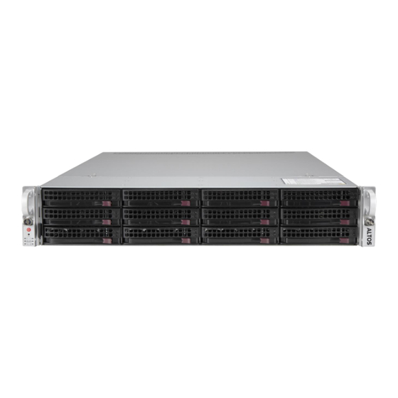
Chapter 1: Introduction 1.2 System Features The following views of the system display the main features. Refer to Appendix B additional specifications. Front View Service/Asset Tag with BMC Password Control Panel Figure 1-1. Front View Logical Storage Drive Numbers Item Description 3.5"... - Page 9 Chapter 1: Introduction Drive Carrier LED Indicators Color Blinking Pattern Behavior for Device Status Solid On Failure of drive with RSTe support Blinking at 1 Hz Rebuild drive with RSTe support Blinking at 4 Hz Identify drive with RSTe support Blinking with two blinks Hot spare for drive with RSTe support and one stop at 1 Hz...
- Page 10 Chapter 1: Introduction Information LED Color, Status Description Red, solid An overheat condition has occurred. Red, blinking at 1Hz Fan failure, check for an inoperative fan. Power failure, check for a non-operational power Red, blinking at 0.25Hz supply. Red, solid, with Power LED blinking Fault detected green Recovery mode...
-
Page 11: Rear View
Indicates that the power supply has a warning condition and continues to operate. Blinking Amber Indicates that the power supply is plugged in, and is in an abnormal state. The Solid Amber system might need service. Please contact ALtos technical support. No AC power to modules... - Page 12 Chapter 1: Introduction Expansion Slots and Riser Cards This system offers options for riser cards that provide custom PCIe capabilities—one Ultra Riser card, one right-facing WIO riser card, and one left-facing WIO card. PCIe Slots per Riser Card Riser Card Part Number Slot Description (all PCIe 4.0) x16 FH, 10.5”L (CPU2)
-
Page 13: Top View
Chapter 1: Introduction Top View Power Supply Modules SATADOM Ports Dual Processors DIMM Slots 4 System Fans Figure 1-4. System: Top View System Features: Top Feature Description Power Supply Dual redundant modules; see options on previous page Disk-on-Module port allows for flash cards to be mounted directly on the motherboard SuperDOM ports Dual in-line memory module (DIMMs) slots DIMM slots... -
Page 14: System Architecture
Chapter 1: Introduction 1.3 System Architecture This section shows the locations of the system electrical components, and a block diagram of the overall system. Main Components Riser Card, Left-facing Ultra Riser Card; (options) Riser Card, Right -facing Motherboard X12DPU-6 Storage Backplane BPN-NVME4-216N-S24 (manual) Figure 1-5. -
Page 15: System Block Diagram
Chapter 1: Introduction System Block Diagram The block diagram below shows the connections and relationships between the subsystems and major components of the overall system. Intel Xeon Intel Xeon ® ® 16 DDR4 DIMM Slots 16 DDR4 DIMM Slots ® ®... -
Page 16: Motherboard Layout
Chapter 1: Introduction 1.4 Motherboard Layout Below is a layout of the X12DPU-6 motherboard with jumper, connector and LED locations shown. See the table on the following page for descriptions. For detailed descriptions, pinout information and jumper settings, Figure 1-7. Motherboard Layout... -
Page 17: Quick Reference
Chapter 1: Introduction Quick Reference Jumper Description Default Setting JBT1 Clear CMOS Open (Normal) JUID UID Enable/System Reset Jumper Pins 1-2 (UID Enabled) Connector Description Onboard CMOS battery COM1 Backplane COM port FAN1 ~ FAN8 CPU/System fan headers FFC (Flat Flexible Cable) connector BMC_LAN Dedicated BMC LAN port (JLAN1) I-SATA 0~3, I-SATA 4~7... -
Page 18: Motherboard Block Diagram
Chapter 1: Introduction Description State: Status LEDM1 BMC Heartbeat LED Blinking Green: BMC Normal LED1 Rear UID (Unit Identifier) LED Solid Blue: Unit Identified Motherboard Block Diagram X12DPU-6 NCSI DDR4 DDR4 AST2600 BMC LAN RTL8211F RJ45 32MB BMC COM1 HWM UART SPI FLASH LPC/eSPI Ultra IO... -
Page 19: Server Installation
Chapter 2: Server Installation Chapter 2 Server Installation 2.1 Overview This chapter provides advice and instructions for mounting your system in a server rack. If your system is not already fully integrated with processors, system memory etc., refer to Chapter 3 for details on installing those specific components. -
Page 20: Rack Precautions
Chapter 2: Server Installation • This product is not suitable for use with visual display workplace devices according to §2 of the German Ordinance for Work with Visual Display Units. Rack Precautions • Ensure that the leveling jacks on the bottom of the rack are extended to the floor so that the full weight of the rack rests on them. - Page 21 Chapter 2: Server Installation Airflow Equipment should be mounted into a rack so that the amount of airflow required for safe operation is not compromised. Mechanical Loading Equipment should be mounted into a rack so that a hazardous condition does not arise due to uneven mechanical loading.
-
Page 22: Installing The Rails
Chapter 2: Server Installation 2.4 Installing the Rails There are a variety of rack units on the market, which may require a slightly different assembly procedure. This rail set fits a rack between 26.8" and 36.4" deep. The following is a basic guideline for installing the system into a rack with the rack mounting hardware provided. -
Page 23: Releasing The Inner Rail
Chapter 2: Server Installation Releasing the Inner Rail Each inner rail has a locking latch. This latch prevents the server from coming completely out of the rack when when the chassis is pulled out for servicing. To mount the rail onto the chassis, first release the inner rail from the outer rails. 1. -
Page 24: Installing The Inner Rails On The Chassis
Chapter 2: Server Installation Installing the Inner Rails on the Chassis Installing the Inner Rails 1. Identify the left and right inner rails. They are labeled. 2. Place the inner rail firmly against the side of the chassis, aligning the hooks on the side of the chassis with the holes in the inner rail. -
Page 25: Installing The Outer Rails Onto The Rack
Chapter 2: Server Installation Installing the Outer Rails onto the Rack Each end of the assembled outer rail includes a bracket with hooks and square, spring- loaded pegs to fit into the square holes in your rack. Installing the Outer Rail 1. -
Page 26: Installing The Chassis Into A Rack
Chapter 2: Server Installation 2.5 Installing the Chassis into a Rack Once rails are attached to the chassis and the rack, you can install the server. Warning: Mounting the system into the rack requires at least two people to support the chassis during installation. -
Page 27: Removing The Chassis From The Rack
Chapter 2: Server Installation Removing the Chassis from the Rack Caution! It is dangerous for a single person to off-load the heavy chassis from the rack without assistance. Be sure to have sufficient assistance supporting the chassis when removing it from the rack. Use a lift. 1. -
Page 28: Maintenance And Component Installation
Chapter 3: Maintenance and Component Installation Chapter 3 Maintenance and Component Installation This chapter provides instructions on installing and replacing main system components. To prevent compatibility issues, only use components that match the specifications and/or part numbers given. Installation or replacement of most components require that power first be removed from the system. -
Page 29: Accessing The System
Chapter 3: Maintenance and Component Installation 3.2 Accessing the System A removable top cover allows access to the inside of the chassis. Removing the Top Cover 1. Remove the two screws on each side of the cover, which secure the cover to the chassis. -
Page 30: Processor And Heatsink Installation
• Thermal grease is pre-applied on new heatsinks. No additional thermal grease is needed. • Refer to the ALtos website for updates on processor support. • Graphics in this manual are for illustration only. Your components may look different. -
Page 31: The Processor Carrier Assembly
Chapter 3: Maintenance and Component Installation The Processor Carrier Assembly The processor carrier assembly is comprised of the processor and the processor carrier. 1. Hold the processor with the land grid array (LGA, gold contacts) facing down. Locate the gold triangle at the corner of the processor and the corresponding hollowed triangle on the processor carrier as shown below. - Page 32 Chapter 3: Maintenance and Component Installation 3. Locate the lever on the carrier and, if necessary, press it down as shown below. Lever 4. Align the CPU keys on the processor (A & B) with those on the carrier (a & b) as shown below.
- Page 33 Chapter 3: Maintenance and Component Installation The Processor Heatsink Module (PHM) After creating the processor carrier assembly, mount the heatsink onto the carrier assembly to form the processor heatsink module (PHM). Note: If this is a new heatsink, the thermal grease has been pre-applied. Otherwise, apply the proper amount of thermal grease to the underside of the heatsink.
- Page 34 Chapter 3: Maintenance and Component Installation Installing the PHM into the CPU Socket 1. Remove the plastic protective cover from the CPU socket. Gently squeeze the grip tabs then pull the cover off. CPU Socket with Plastic Protective Cover Grip Tabs...
- Page 35 Chapter 3: Maintenance and Component Installation 2. Locate four threaded fasteners (a, b, c, d) on the CPU socket. Threaded Fastener CPU Socket (a, b, c, d: Threaded Fasteners) CPU Socket Pin1 3. Locate four PEEK nuts (A, B, C, D) and four rotating wires (1, 2, 3, 4) on the heatsink as shown below.
- Page 36 Chapter 3: Maintenance and Component Installation 5. Align nut A (next to the triangles and pin 1) on the heatsink with threaded fastener "a" on the CPU socket. Also align nuts B, C, D on the heatsink with threaded fasteners b, c, d on the CPU socket.
- Page 37 Chapter 3: Maintenance and Component Installation Removing the PHM from the CPU Socket Be sure the system is shut down and all AC power cords are unplugged. 1. Use a t30-bit screwdriver to loosen the four PEEK nuts on the heatsink in the sequence of A, B, C, and D.
- Page 38 Chapter 3: Maintenance and Component Installation Removing the Processor Carrier Assembly from the PHM Detach the four plastic clips (a, b, c, d) on the processor carrier assembly from the four corners of the heatsink (A, B, C, D) as shown below, and lift off the processor carrier assembly. Processor Carrier Assembly Pin 1 Pin 1...
- Page 39 Chapter 3: Maintenance and Component Installation Removing the Processor from the Carrier Assembly Unlock the lever from its locked position and push it upwards to disengage the processor from the carrier as shown below right. Carefully remove the processor from the carrier. Processor Carrier Assembly Lever Note: Handle the processor with care to avoid damage.
-
Page 40: Memory Support
Chapter 3: Maintenance and Component Installation 3.4 Memory Memory Support The X12DPU-6 motherboard has 32 DIMM slots. It supports up to • 8TB (DDR4 only): 3DS Load Reduced DIMM (3DS LRDIMM), 3DS Registered DIMM (3DS RDIMM), or Non-Volatile DIMMs (NV-DIMM) ECC memory with speeds of up to 3200 MHz. •... - Page 41 Chapter 3: Maintenance and Component Installation Guidelines Regarding Mixing DIMMs • All DIMMs must be DDR4 or a mixture of PMem and DDR4. • x4 and x8 DIMMs can be mixed in the same channel. • Mixing of LRDIMMs and RDIMMs is not allowed in the same channel, across different channels, and across different sockets.
- Page 42 Chapter 3: Maintenance and Component Installation DDR4 Memory Population Guidelines The following memory population table was created based on guidelines provided by Intel to support ALtos motherboards. Memory Population for DDR4-only Configurations, 32 DIMM Slots CPUs/DIMMs DIMM Slots CPU1: A1 2 CPUs &...
- Page 43 Chapter 3: Maintenance and Component Installation Optane PMem 200 Series For 3rd Gen Intel Xeon Scalable Platinum, Gold and selected Silver processors Symmetric Population for Each CPU with PMem + DDR4 DIMM DDR4 & Modes interl- PMem leve 4 DDR4 1 - x4 DDR4 DDR4...
- Page 44 Chapter 3: Maintenance and Component Installation PMem Notes • PMem 200 Series are supported on 3rd gen Intel Xeon Scalable Platinum, Gold and se- lected Silver processors. • Do not mix PMem and NVDIMMs within the platform. • For MM, NM/FM ratio is between 1:4 and 1:16. The capacity not used for FM can be used for AD.
-
Page 45: Installing Memory
Chapter 3: Maintenance and Component Installation Installing Memory ESD Precautions Electrostatic Discharge (ESD) can damage electronic com-ponents including memory modules. To avoid damaging DIMM modules, it is important to handle them carefully. The following measures are generally sufficient. • Use a grounded wrist strap designed to prevent static discharge. •... -
Page 46: Motherboard Battery
Chapter 3: Maintenance and Component Installation 3.5 Motherboard Battery The motherboard uses non-volatile memory to retain system information when system power is removed. This memory is powered by a lithium battery residing on the motherboard. Replacing the Battery Begin by removing power from the system. -
Page 47: Storage Drives
Chapter 3: Maintenance and Component Installation 3.6 Storage Drives The system supports twelve hot-swap 3.5" hybrid storage drive bays The drives are mounted in tool-less drive carriers that simplify their removal from the chassis. These carriers also help promote proper airflow. Installing Drives Figure 3-5. - Page 48 Removing a Hot-Swap Drive Carrier from the Chassis 1. Press the release button on the drive carrier, which will extend the drive carrier handle. 2. Use the drive carrier handle to pull the drive out of the chassis. Figure 3-6. Removing a Drive Carrier...
- Page 49 Chapter 3: Maintenance and Component Installation Installing a 3.5" Drive 1. Remove the dummy drive, which comes pre-installed in the drive carrier. Pull out the two locking clasps on the right outside of the carrier and lift out the dummy drive. 2.
-
Page 50: Checking The Temperature Of An Nvme Drive
Chapter 3: Maintenance and Component Installation Insert this side second Figure 3-8. Installing a 3.5" Drive into a Carrier Checking the Temperature of an NVMe Drive There are two ways to check using the BMC Dashboard. Checking a Drive • BMC Dashboard >... -
Page 51: Hot-Swap For Nvme Drives
Chapter 3: Maintenance and Component Installation Hot-Swap for NVMe Drives ALtos Ultra servers support NVMe surprise hot-swap. For even better data security, NVMe orderly hot-swap is recommended. NVMe drives can be ejected and replaced remotely using the BMC Dashboard. Note: If you are using VROC, see the VROC section in this manual instead. -
Page 52: System Cooling
2. Push the release tab and pull the failed fan from the chassis. Fans can be replaced while the system is running. 3. Replace the failed fan with an identical fan, available from ALtos. Push the new fan into the housing, making sure the air flow direction is the same. -
Page 53: Air Shrouds
Chapter 3: Maintenance and Component Installation Air Shrouds Air shrouds concentrate airflow to maximize fan efficiency. They do not require screws to install. Installing the Standard Air Shrouds • Position the air shrouds as illustrated in the figure below. Shrouds Figure 3-11. -
Page 54: Power Supply Leds
• Solid Amber: When illuminated, indicates that the power supply is plugged in, and is in an abnormal state. The system might need service. Please contact ALtos technical support. Changing the Power Supply Module: 1. Unplug the AC cord from the module to be replaced. -
Page 55: Pci Expansion Slots
Chapter 3: Maintenance and Component Installation 3.9. PCI Expansion Slots This system offers options for riser cards that provide custom PCIe capabilities—one Ultra Riser card, one right-facing WIO riser card, and one left-facing WIO card. Figure 3-13. Expansion Card Chassis Slots PCIe Slots per Riser Card Riser Card Part Number... - Page 56 Chapter 3: Maintenance and Component Installation Installing Full Height Expansion Cards Riser Card Brackets Figure 3-14. Installing Expansion Cards Installing PCI Expansion Cards 1. Power down the system and remove the top chassis cover. 2. Remove the riser card bracket, pictured above. On the rear of the chassis, each bracket is secured by a small black plastic flip-lever with an arrow on it.
- Page 57 Chapter 3: Maintenance and Component Installation Installing the Low Profile Center Expansion Card Riser Card Slot Figure 3-15. Installing Low Profile Expansion Card Installing the Low Profile PCI Expansion Card ( 1. Power down the system and remove the top chassis cover. 2.
- Page 58 Chapter 3: Maintenance and Component Installation Installing the Internal Expansion Card For most models, the Ultra riser card that holds the LAN ports also offers another internal low profile card slot ( ). Installation is pictured below. View from Front of Chassis Thumb Screw to Secure Bracket...
-
Page 59: Removing The Ultra Riser Card
Chapter 3: Maintenance and Component Installation Ultra Riser and Expansion Cards with Optional Storage Drives This server supports an option to add two storage drives in place of expansion cards. View from Front of Chassis View from Rear of Chassis Optional Cage for Two Storage Drives Figure 3-18. -
Page 60: Cable Routing Diagram
Chapter 3: Maintenance and Component Installation 3.10 Cable Routing Diagram Use this section to route or reroute cables. Proper routing is important to maintain airflow through the system. SAS cable routing depends on the model and position of the SAS controller card, so routing is not shown here. -
Page 61: Motherboard Connections
Chapter 4: Motherboard Connections Chapter 4 Motherboard Connections This section describes the connections on the motherboard and provides pinout definitions. Note that depending on how the system is configured, not all connections are required. The LEDs on the motherboard are also described here. A motherboard layout indicating component locations may be found in Chapter 1. -
Page 62: Headers And Connectors
Chapter 4: Motherboard Connections 4.2 Headers and Connectors Fan Headers There are eight fan headers on the motherboard. These are 4-pin fan headers, although pins 1-3 are backward compatible with traditional 3-pin fans. Four-pin fans allow fan speeds to be controlled by Thermal Management in the BMC. - Page 63 The JTPM1 header is used to connect a Trusted Platform Module (TPM)/Port 80, which is available from ALtos. A TPM/Port 80 connector is a security device that supports encryption and authentication in hard drives. It allows the motherboard to deny access if the TPM associated with the storage drive is not installed in the system.
- Page 64 Chapter 4: Motherboard Connections RAID Key Header An Intel VROC RAID Key header is located at JRK1. It supports VMD used in creating optional advanced NVMe RAID configurations. RAID Key Header Pin Definitions Pin# Definition Ground RAID_KEY_PU Ground PCH_RAID_KEY VROC Key Note: This drawing is for illustration only.
- Page 65 Chapter 4: Motherboard Connections Control Panel JF1 contains header pins for various control panel connections. See the figure below for the pin locations and definitions of the control panel buttons and LED indicators. All JF1 wires have been bundled into a single cable to simplify this connection. Make sure the red wire plugs into pin 1 as marked on the motherboard.
- Page 66 Chapter 4: Motherboard Connections Power Fail LED The Power Fail LED connection is located on pins 5 and 6 of JF1. Power Fail LED Pin Definitions (JF1) Pin# Definition 3.3V PWR Supply Fail Overheat (OH)/Fan Fail Connect an LED cable to pins 7 and 8 of JF1 to use the Overheat/Fan Fail LED connections. The LED on pin 8 provides warnings of overheat or fan failure.
- Page 67 Chapter 4: Motherboard Connections Power LED The Power LED connection is located on pins 15 and 16 of JF1. Power LED Pin Definitions (JF1) Pin# Definition 3.3V Power LED NMI Button The non-maskable interrupt button header is located on pins 19 and 20 of JF1. NMI Button Pin Definitions (JF1) Pin#...
-
Page 68: Input/Output Ports
Chapter 4: Motherboard Connections 4.3 Input/Output Ports See the figure below for the locations and descriptions of the I/O ports on the rear of the motherboard. Figure 4-2. Rear I/O Ports Rear I/O Ports Description Description USB0 (3.0) COM1 USB1 (3.0) UID Switch Dedicated BMC LAN LAN Ports... - Page 69 Chapter 4: Motherboard Connections 4.4 Jumpers Explanation of Jumpers To modify the operation of the motherboard, jumpers are used to choose between optional settings. Jumpers create shorts between two pins to change the function associated with it. Pin 1 is identified with a square solder pad on the printed circuit board. See the motherboard layout page for jumper locations.
- Page 70 Chapter 4: Motherboard Connections VGA/Video Display Enable Jumper JPG1 enables or disables onboard VGA support. When this jumper is set to Disabled, both rear VGA port, located at I/O back panel, and the optional front accessible VGA header, located at JVGA2 are disabled. The default setting is on pins 1-2 to enable the connection for VGA support.
-
Page 71: Led Indicators
Chapter 4: Motherboard Connections 4.5 LED Indicators Network LAN LEDs The Ethernet ports each have two LEDs. One LED indicates activity when flashing green. The other may be green, amber or off to indicate the speed of the connection. Speeds noted in Chapter 1. -
Page 72: Storage Ports
4.6 Storage Ports I-SATA 3.0 and S-SATA 3.0 Ports The R380 F5 has eight I-SATA 3.0 ports (I-SATA 0-3, I-SATA 4-7) and six S-SATA (S-SATA 0-3, S-SATA 4, S-SATA 5) on the motherboard. These SATA ports are supported by the Intel PCH C621 chipset. -
Page 73: Appendix A: Warning Statements
Should you have questions or experience difficulty, contact ALtos's Technical Support department for assistance. Only certified technicians should attempt to install or configure components. Read this appendix in its entirety before installing or configuring components in the ALtos chassis. Warning Definition Warning! This warning symbol means danger. - Page 74 Appendix A: Warning Statements Warnung WICHTIGE SICHERHEITSHINWEISE Dieses Warnsymbol bedeutet Gefahr. Sie befinden sich in einer Situation, die zu Verletzungen führen kann. Machen Sie sich vor der Arbeit mit Geräten mit den Gefahren elektrischer Schaltungen und den üblichen Verfahren zur Vorbeugung vor Unfällen vertraut. Suchen Sie mit der am Ende jeder Warnung angegebenen Anweisungsnummer nach der jeweiligen Ü...
-
Page 75: Installation Instructions
Appendix A : Warning Statements ً ك ف حالة ٌيكو أى تتسبب ف اصابة جسذ ة ٌ هذا الزهز ٌع خطز !تحذ ٌز . قبل أى تعول عىل ا أي هعذات،يك عىل علن بالوخاطز اٌل ٌ جوة عي الذوائز الكهزب ائ... -
Page 76: Circuit Breaker
Appendix A: Warning Statements Warnung Vor dem Anschließ en des Systems an die Stromquelle die Installationsanweisungen lesen. ¡Advertencia! Lea las instrucciones de instalación antes de conectar el sistema a la red de alimentación. Attention Avant de brancher le système sur la source d'alimentation, consulter les directives d'installation. .חתמ... - Page 77 Appendix A: Warning Statements Warnung Dieses Produkt ist darauf angewiesen, dass im Gebäude ein Kurzschluss- bzw. Ü berstromschutz installiert ist. Stellen Sie sicher, dass der Nennwert der Schutzvorrichtung nicht mehr als: 250 V, 20 A beträgt. ¡Advertencia! Este equipo utiliza el sistema de protección contra cortocircuitos (o sobrecorrientes) del edificio.
-
Page 78: Power Disconnection Warning
Appendix A: Warning Statements Power Disconnection Warning Warning! The system must be disconnected from all sources of power and the power cord removed from the power supply module(s) before accessing the chassis interior to install or remove system components. 電源切断の警告 システムコンポーネントの取り付けまたは取り外しのために、シャーシー内部にアクセスする... -
Page 79: Equipment Installation
Appendix A: Warning Statements ילמשח קותינ ינפמ הרהזא !הרהזא ה תורוקמ לכמ תכרעמה תא קתנל קפסהמ ילמשחה לבכ תא ריסהל שיו למשח .שי םיביכר תרסה וא תנקתה ךרוצל זראמה לש ימינפה קלחל השיג ינפל دادما ةدحو نم ءابرهكنا كهس تنازإو تقاطنا رداصم عيمج نم واظننا مصف بجي مبق... -
Page 80: Restricted Area
Appendix A: Warning Statements ¡Advertencia! Solamente el personal calificado debe instalar, reemplazar o utilizar este equipo. Attention Il est vivement recommandé de confier l'installation, le remplacement et la maintenance de ces équipements à des personnels qualifiés et expérimentés. !הרהזא .דויצה רובע תוריש תתל וא דויצה תא ףילחהל ,ןיקתהל יאשר דבלב ךמסומ תווצ هيلهؤلما... - Page 81 Appendix A: Warning Statements Warnung Diese Einheit ist zur Installation in Bereichen mit beschränktem Zutritt vorgesehen. Der Zutritt zu derartigen Bereichen ist nur mit einem Spezialwerkzeug, Schloss und Schlüssel oder einer sonstigen Sicherheitsvorkehrung möglich. ¡Advertencia! Esta unidad ha sido diseñada para instalación en áreas de acceso restringido. Sólo puede obtenerse acceso a una de estas áreas mediante la utilización de una herramienta especial, cerradura con llave u otro medio de seguridad.
-
Page 82: Battery Handling
Appendix A: Warning Statements Battery Handling Warning! There is the danger of explosion if the battery is replaced incorrectly. Replace the battery only with the same or equivalent type recommended by the manufacturer. Dispose of used batteries according to the manufacturer's instructions 電池の取り扱い... -
Page 83: Redundant Power Supplies
Appendix A : Warning Statements هناك خطر من انفجار يف حالة اسحبذال البطارية بطريقة غري صحيحة فعليل اسحبذال البطارية نفس النىع أو ما يعادلها مام أوصث به الرشمة املصنعة فقط ب جخلص من البطاريات املسحعملة وفقا لحعليامت الرشمة الصانعة 경고! 배터리가... - Page 84 Appendix A: Warning Statements ¡Advertencia! Puede que esta unidad tenga más de una conexión para fuentes de alimentación. Para cortar por completo el suministro de energí a, deben desconectarse todas las conexiones. Attention Cette unité peut avoir plus d'une connexion d'alimentation. Pour supprimer toute tension et tout courant électrique de l'unité, toutes les connexions d'alimentation doivent être débranchées.
-
Page 85: Backplane Voltage
Appendix A: Warning Statements Backplane Voltage Warning! Hazardous voltage or energy is present on the backplane when the system is operating. Use caution when servicing. バックプレーンの電圧 システムの稼働中は危険な電圧または電力が、バックプレーン上にかかっています。 修理する際には注意ください。 警告 当系统正在进行时,背板上有很危险的电压或能量,进行维修时务必小心。 警告 當系統正在進行時,背板上有危險的電壓或能量,進行維修時務必小心。 Warnung Wenn das System in Betrieb ist, treten auf der Rückwandplatine gefährliche Spannungen oder Energien auf. -
Page 86: Comply With Local And National Electrical Codes
Appendix A: Warning Statements ةحىلال لىع ةدىجىلما ةقاطالوأ ئيابزهكال رايتال هم زطخ كانه ساهجال اذه ةمدخ دنع ارذح هك لمعي ماظنال نىكي امدنع 경고! 시스템이 동작 중일 때 후면판 (Backplane)에는 위험한 전압이나 에너지가 발생 합니다. 서비스 작업 시 주의하십시오. Waarschuwing Een gevaarlijke spanning of energie is aanwezig op de backplane wanneer het systeem in gebruik is. -
Page 87: Product Disposal
Appendix A: Warning Statements יצראה למשחה יקוח םואית !הרהזא . םייצראהו םיימוקמה למשחה יקוחל תמאות תויהל תבייח דויצה תנקתה ةقلعتلما ةيىطىالو ةيلحلما هيواىقلل لثتيم نأ بجي ةيئابرهكال تادعلما بيكرت ءابرهكالب 경고! 현 지역 및 국가의 전기 규정에 따라 장비를 설치해야 합니다. Waarschuwing Bij installatie van de apparatuur moet worden voldaan aan de lokale en nationale elektriciteitsvoorschriften. -
Page 88: Hot Swap Fan Warning
Appendix A: Warning Statements Attention La mise au rebut ou le recyclage de ce produit sont généralement soumis à des lois et/ou directives de respect de l'environnement. Renseignez-vous auprès de l'organisme compétent. רצומה קוליס !הרהזא . הנידמה יקוחו תויחנהל םאתהב תויהל בייח הז רצומ לש יפוס קוליס دنع... - Page 89 Appendix A: Warning Statements Warnung Gefährlich Bewegende Teile. Von den bewegenden Lüfterblätter fern halten. Die Lüfter drehen sich u. U. noch, wenn die Lüfterbaugruppe aus dem Chassis genommen wird. Halten Sie Finger, Schraubendreher und andere Gegenstände von den Ö ffnungen des Lüftergehäuses entfernt.
-
Page 90: Power Cable And Ac Adapter
Electrical Appliance and Material Safety Law prohibits the use of UL or CSA -certified cables (that have UL/CSA shown on the cord) for any other electrical devices than products designated by ALtos only. 電源コードと AC アダプター... - Page 91 -הבטיחות ,קיים איסור להשתמש בכבלים המוסמכים בUL -או בCSA ( כאשר מופיע עליהם קוד של (UL/CSA עבור כל מוצר חשמלי אחר ,אלא רק במוצר אשר הותאם ע"יALtos .בלבד تالباكال ءارشب مق وأ ةددحمال وأ ةرفوتمال تاليصوتال مادختساب مق ،جتنمال بيكرت دنع...
- Page 92 사항을 준수하여 제공되거나 지정된 연결 혹은 구매 케이블, 전원 케이블 및 AC 어댑터를 사용하십시오. 다른 케이블이나 어댑터를 사용하면 오작동이나 화재가 발생할 수 있습니다. 전기 용품 안전법은 UL 또는 CSA 인증 케이블 (코드에 UL / CSA 가 표시된 케이블)을 ALtos 가 지정한 제품 이외의 전기 장치에 사용하는 것을 금지합니다. Stroomkabel en AC-Adapter...
Need help?
Do you have a question about the R380 F5 and is the answer not in the manual?
Questions and answers