Advertisement
Quick Links
Advertisement

Related Manuals for Altos Altos BrainSphere R365 F5


Summary of Contents for Altos Altos BrainSphere R365 F5
- Page 1 Altos BrainSphere™ R365 F5 User Guide Revision 1.0...
- Page 2 System setup System notes Thank you for purchasing your Altos server. This user guide is intended as a reference for experienced server technicians and helps detail many of the features available in Altos servers. For more detailed information about any component or software solution, you may consult the technical specifications or the user manual for that application.
-
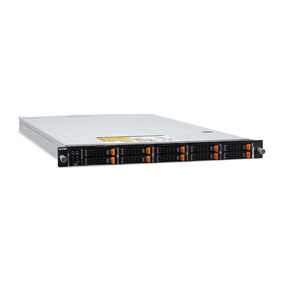
Page 3: System Component Identification
System Component Identification Altos BrainSphere™ R365 F5 (LFF SKU): Front View: Description Front USB 3.0 Ports Front Panel LEDs and Buttons Rear View: Description Description PCIe card slot x 2 GbE LAN port x 2 Mezzanine card slot (Option/OCP USB 3.0 port x 2 3.0/SFF) - Page 4 Altos BrainSphere™ R365 F5 (SFF SKU): Front View: Description Front USB 3.0 Port Front Panel LEDs and Buttons Rear View: Description Description PCIe card slot x 2 GbE LAN port x 2 Mezzanine card slot (Option/OCP USB 3.0 port x 2 3.0/SFF)
-
Page 5: System Controls And Indicators
System controls and indicators Altos BrainSphere™ R365 F5 (LFF SKU) front panel LEDs and Buttons: Name Color Status Description NMI Button Press this button for the server to generate a NMI to the processor. If multiple-bit ECC errors occur, the server will effectively be halted. - Page 6 Name Color Status Description • System fan failure • System temperature Blink Indicates non-critical condition, may include: • Redundant power module failure • Temperature and voltage issue • Chassis intrusion Indicates system is not ready, may include: • POST error •...
- Page 7 Altos BrainSphere™ R365 F5 (SFF SKU) front panel LEDs and Buttons: Name Color Status Description Reset Button Press this button to reset the system. NMI Button Press this button for the server to generate a NMI to the processor. If multiple-bit ECC errors occur, the server will effectively be halted.
- Page 8 Name Color Status Description may include: • Redundant power module failure • Temperature and voltage issue • Chassis intrusion Indicates system is not ready, may include: • POST error • NMI error • Processor or terminator is missing LAN1 Activity Green Indicates a link between the system and the network or no access.
- Page 9 Rear System LAN LEDs: Name Color Status Description 1GbE Speed Yellow 1 Gbps data rate Green 100 Mbps data rate 10 Mbps data rate 1GbE Green Link between system and Link/Activity network or no access Data transmission or receiving is Blink occurring No data transmission or receiving is...
- Page 10 Hard Disk Drive LEDs: No RAID configuration (via HBA): LED #1 Locate Rebuilding HDD Access HDD Present Fault (No Access) Disk LED Green ON (*1) BLINK (*2) (LED on Back Amber Panel) Removed Green ON (*1) HDD Slot Amber (LED on Back Panel) RAID configuration (via HW RAID Card or SW RAID Card) LED #1...
- Page 11 Setting up the system Pre-installation requirements Selecting a site Before unpacking and installing the system, select a suitable site for the system for maximum efficiency. Consider the following factors when choosing a site for the system: Near a grounded power outlet. ⚫...
- Page 12 Turning on the system After making sure that you have properly set up the system, applied power and connected all the necessary peripherals, you can now power on the system. Follow the procedure below. Press the power button 。 The system starts up and displays a welcome message on the monitor. After that, a series of power-on self-test (POST) messages appears.
- Page 13 Note: If you have gone through the preceding actions and the system still fails to boot, ask your dealer or a qualified technician for assistance.
- Page 14 Turning off the system There are two ways to turn off the server—via software or via hardware. The software procedure below applies to a system running on a Windows OS. For other shutdown procedures, refer to the related user documentation. To turn off the system via software: Press <Ctrl>...
- Page 15 System troubleshooting Resetting the system Before going through in-depth troubleshooting, attempt first to reset the system using one of the methods below. Perform Purpose To do this Soft boot To clear the system memory and Press <Ctrl> + <Alt> + <Del> reload the operating system.
- Page 16 Initial system startup problems Problems that occur at initial system startup are usually caused by an incorrect installation or configuration. Hardware failure is a less possible cause. If the problem you are experiencing is with a specific application. Initial troubleshooting checklist AC power is available at the wall outlet? ⚫...
- Page 17 Hardware diagnostic testing This section provides a detailed approach to identifying a hardware problem and its cause. Checking the boot-up status Caution: Before disconnecting any peripheral cables from the server, turn off the system and any peripheral devices. Failure to do so can cause permanent damage to the system and/or the peripheral device.
- Page 18 Specific problems and corrective actions Listed below are specific problems that may arise during the use of your server and their possible solutions Confirming loading of the operating system Once the system boots up, the operating system prompt appears on the screen. The prompt varies according to the operating system.
- Page 19 Check that relevant switches and jumpers on the hard drive and on the backplane ⚫ board are set correctly. Optical drive activity indicator does not light Do the following: Make sure the SATA and power cables are properly connected. ⚫ Check that relevant switches and jumpers on the drive are set correctly.
- Page 20 Peripheral device connected to a USB port does not work. Do the following: Reduce the number of external devices connected to a USB hub. ⚫ Refer to the documentation that came with the device ⚫ There is problem with the software program. Do the following: Verify that the software is properly configured for the system.
- Page 21 If POST does not emit any beep code and characters still do not appear, the display monitor or the video controller may be defective. Contact your local Altos representative or authorized dealer for technical assistance.
- Page 22 Notices Information for your safety and comfort Safety instructions Read these instructions carefully. Keep this document for future reference. Follow all warnings and instructions marked on the product. Turning the product off before cleaning Unplug this product from the wall outlet before cleaning. Do not use liquid cleaners or aerosol cleaners.
- Page 23 provided. Never push objects of any kind into this product through cabinet slots as they may ⚫ touch dangerous voltage points or short-out parts that could result in a fire or electric shock. Never spill liquid of any kind onto or into the product. To avoid damage of internal components and to prevent battery leakage, do not ⚫...
- Page 24 with the performance of this product. Use the product only with the supplied power supply cord set. If you need to ⚫ replace the power cord set, make sure that the new power cord meets the following requirements: detachable type, UL listed/CSA certified, VDE approved or its equivalent, 4.6 meters (15 feet) maximum length.
- Page 25 Do not throw this electronic device into the trash when discarding. To minimize pollution and ensure utmost protection of the global environment, please recycle...
-
Page 26: Regulations And Safety Notices
Precaução: Radiação laser invisível quando aberto. Evite exposição ao feixe. Laserproduct klasse 1 Voorzichtig: Onzichtbare laserstraling indien geopend. Voorkom blootstelling aan straal. Declaration of Conformity for EU countries Hereby, Altos, declares that this system is in compliance with the essential requirements and other relevant provisions of Directive 1999/5/EC. - Page 27 List of applicable countries This device must be used in strict accordance with the regulations and constraints in the country of use. For further information, please contact local office in the country of use. Please see http://ec.europa.eu/enterprise/rtte/implem.htm or the latest country list. Note: The following sections are applicable only to Class A systems FCC notice Class A...
- Page 28 Caution Changes or modifications not expressly approved by the manufacture could void the user’s authority, which is granted by the Federal Communications Commision Commission, to operate this computer. Operation conditions This device complies with Part 15 of the FCC Rules. Operation is subject to the following two conditions: (1) this device may not cause harmful interference, and (2) this device must accept any interference received, including interference that may cause undesired operation.
Need help?
Do you have a question about the Altos BrainSphere R365 F5 and is the answer not in the manual?
Questions and answers